Data collection and validation
Grounding, winding resistance, transformer construction and line data gathered from TOs and GOs, with gaps flagged and defensible assumptions documented.

Your Trusted Partner in Electrical Engineering and Power Systems
At Keentel Engineering, we deliver electrical power engineering services built on 30 years of experience and a commitment to excellence. Our clients include utilities, developers, EPCs, and public agencies across the U.S.
Unlike firms that sacrifice technical depth to chase billable hours, we prioritize precision, compliance, and value engineering. From transmission services and relay modeling to winterization and SCADA planning, we never compromise on quality.

At Keentel Engineering, we take pride in being the go-to electrical power engineering firm for power and utility system planning, substation design, protection, control, and power system analysis. The following attributes distinguish our team in utility-grade substation engineering and compliance-driven project delivery.
With three decades of hands-on project delivery, we bring unmatched expertise in substation layout design, substation electrical and civil engineering, relay protection, and grid-tie solutions. Our experience includes projects in complex terrain, urban retrofit environments, and utility-scale renewable integrations.
Our engineering process applies AutoCAD 3D, BIM modeling, and system-level substation design practices to ensure accurate planning, reduced errors, and efficient coordination across all project stakeholders.
Our workflow includes 3D substation design, enabling clash-free coordination between structural, electrical, and civil disciplines.
From grounding grid studies to relay protection settings, we engineer every detail to improve system reliability, performance, and operational safety. Our rigorous QA/QC process ensures compliance with IEEE, NFPA, and ISO/TSO interconnection standards.
Among leading electrical substation design companies, Keentel Engineering stands out for 30+ years of proven high-voltage and utility-grade project delivery.




First name, email and what you're interested in are all we need to get moving. Everything else, including drawings or an RFP, is optional.
During a geomagnetic disturbance, rapid changes in the earth’s magnetic field induce a geoelectric field across the earth’s surface. Long transmission lines connected between grounded substations complete a circuit, and a quasi-DC geomagnetically induced current (GIC) flows through the lines, the grounded wye windings of power transformers and the substation grounding grid.
A few tens of amperes of DC in a transformer winding can offset the core flux enough to drive the core into half-cycle saturation. Once that happens, the transformer draws large, distorted magnetizing current. The effects cascade from the equipment to the system:
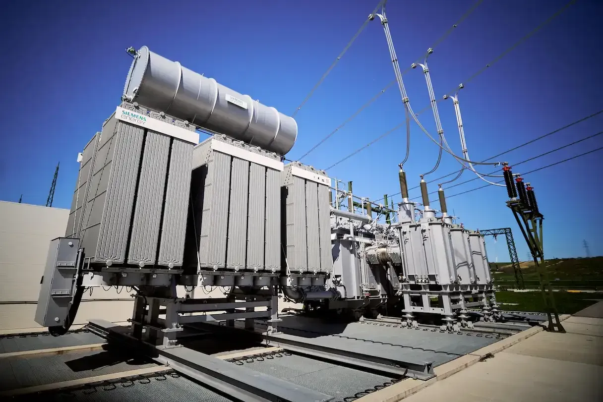
TPL-007 applies to Planning Coordinators and Transmission Planners with planning areas that include a power transformer with a high-side wye-grounded winding connected at 200 kV or higher, and to Transmission Owners and Generator Owners that own such transformers. Confirm the version in effect and its implementation dates for your planning area.
| Requirement area | Primary responsibility | Engineering evidence we produce |
|---|---|---|
| Responsibilities and coordination | PC and TP | Documented individual and joint responsibilities for models, studies and data exchange across the planning area |
| System models and GIC system models | PC and TP, with TO/GO data | Steady-state and GIC system models representing the planning area, with sources for every parameter |
| Benchmark GMD Vulnerability Assessment | PC and TP | Assessment against the benchmark GMD event, performance evaluation and results documentation |
| Transformer thermal impact assessment (benchmark) | TO and GO | Thermal assessments for applicable transformers exceeding the screening criterion, using GIC flow data provided by the planner |
| Corrective Action Plans | PC and TP, with affected entities | Plans where benchmark performance requirements are not met, with timelines and tracking |
| Supplemental GMD Vulnerability Assessment | PC and TP | Assessment against the supplemental GMD event and evaluation of possible actions where results warrant |
| Transformer thermal impact assessment (supplemental) | TO and GO | Thermal assessments for applicable transformers under the supplemental event |
| GMD measurement data | TO (GIC monitors); PC/TP (magnetometer data) | GIC monitor process, data collection and magnetometer data access documentation |
GIC studies use a DC network model separate from the AC power-flow model. Its accuracy depends on data that is rarely in a planning case, so building it is often the largest part of the first assessment.
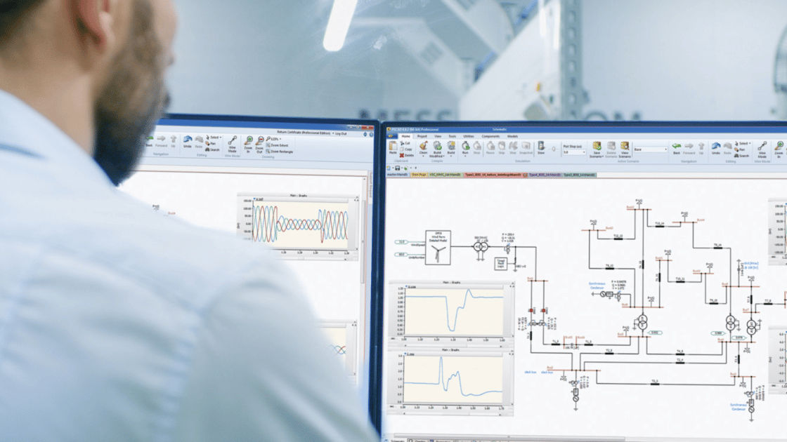
The GIC model produces effective GIC for each transformer. Those values drive the reactive power losses applied to the AC model for the vulnerability assessment and identify which transformers need a thermal impact assessment. We build and run GIC and power-flow analysis in PSS®E and cross-check critical results with hand calculations and equipment data.

Grounding, winding resistance, transformer construction and line data gathered from TOs and GOs, with gaps flagged and defensible assumptions documented.
DC network model built and maintained alongside the planning case, updated for new substations, lines and transformers.
GIC flows, reactive losses and steady-state performance evaluated against the benchmark event and the standard’s performance criteria.
Assessment against the supplemental event representing localized geoelectric field enhancement, with evaluation of possible actions where needed.
Hot-spot and metallic-part heating evaluated for transformers above the screening threshold, using manufacturer data or recognized generic thermal response models.
Mitigation alternatives, technical justification, implementation schedules and tracking to completion.
GIC monitor siting and data processes for TOs; magnetometer data access and documentation for PCs and TPs.
Alignment of planning results with the operating procedures RCs and TOPs maintain for GMD events.
TPL-007 requires the planner to assess the system against two defined scenarios, each with its own geoelectric field definition and follow-up obligations.
Represents a severe, low-probability storm applied as a spatially uniform geoelectric field across the planning area, scaled for latitude and earth conductivity. The planner evaluates steady-state performance with transformer reactive losses included, and where performance requirements are not met, a Corrective Action Plan is required. Transformers whose effective GIC exceeds the standard’s screening threshold — 75 A per phase for the benchmark event — require a thermal impact assessment by the owner.
Represents localized enhancement of the geoelectric field, a higher-intensity field over a limited area. The assessment identifies whether localized peaks create conditions such as Cascading, and the planner evaluates possible actions where they do. Owners perform supplemental thermal impact assessments for transformers exceeding the applicable threshold.
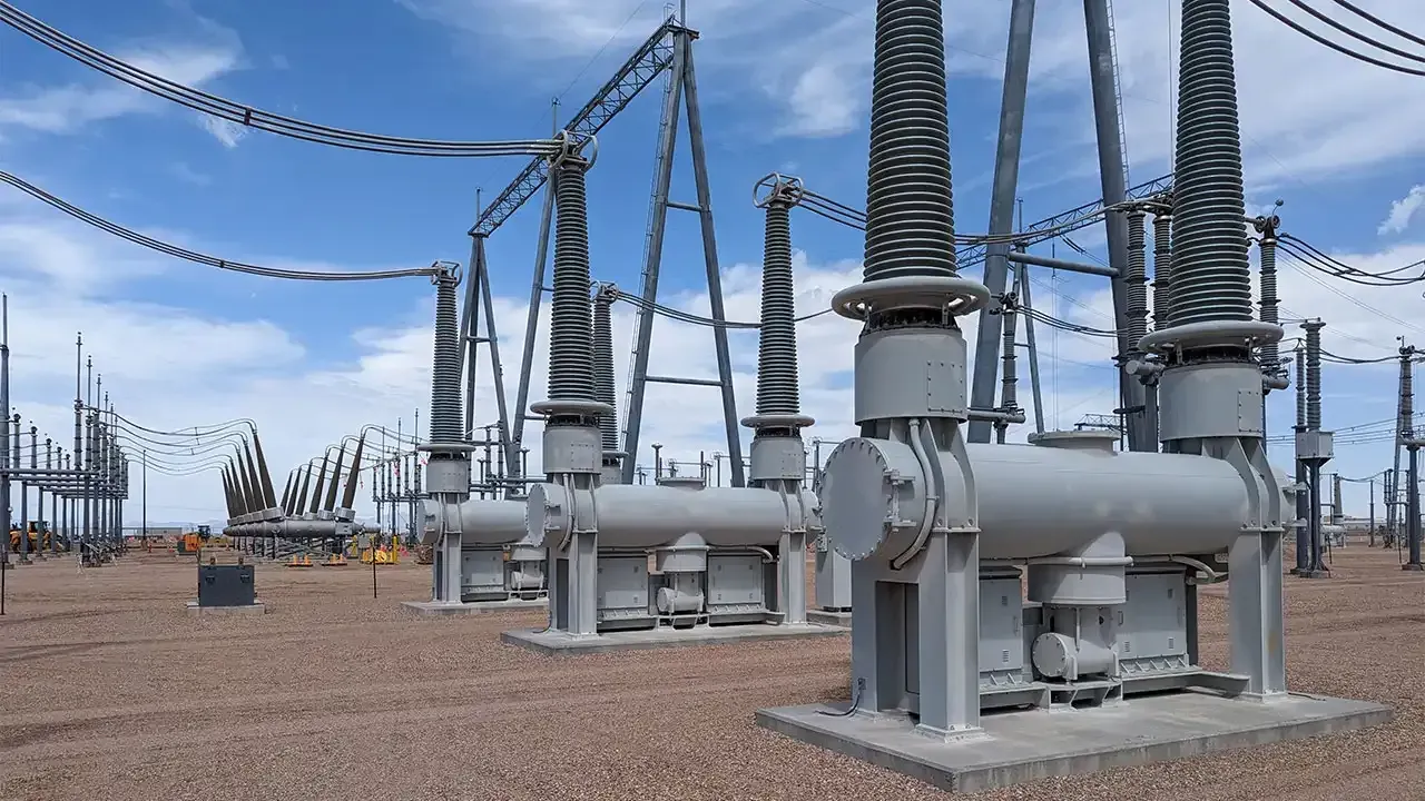
When the assessment shows unacceptable performance or transformer heating, several technical options are available. Most programs combine more than one.
| Mitigation option | Advantages | Limitations |
|---|---|---|
| Neutral blocking devices (capacitive) | Blocks GIC at the transformer where it is installed; targeted to the most exposed units | Can redistribute GIC to neighboring transformers; requires system-wide re-study, protection review and grounding-safety design |
| Series capacitors on transmission lines | Blocks DC on the line; may also increase transfer capability | High cost; subsynchronous resonance and protection impacts must be studied; redistributes GIC elsewhere |
| Transformer specification and replacement | GIC withstand and thermal capability built into new units; long-term solution | Long lead times and high cost; practical mainly at planned replacement |
| Operating procedures (EOP-010) | Low cost; can be implemented quickly using space-weather alerts | Relies on forecasting and operator action; does not remove equipment exposure |
| Protection setting changes | Reduces harmonic-driven misoperation of relays and capacitor bank protection | Needs harmonic analysis and careful coordination; does not reduce GIC itself |
| Reactive reserves and voltage support | Offsets reactive losses and supports voltage during an event | Addresses the system symptom, not transformer heating; capital cost for new devices |
Review the system model, transformer data and mitigation evidence before the next planning assessment or compliance review.
Document PC, TP, TO and GO roles and data exchange for the planning area.
Grounding, winding, transformer construction and line route data, with documented assumptions for any gaps.
Develop or update the DC network model and link it to the current planning case.
Calculate GIC and reactive losses under the benchmark and supplemental events and evaluate system performance.
Provide GIC data to owners and perform thermal impact assessments for transformers above the threshold.
Develop Corrective Action Plans or evaluate possible actions, re-study the chosen mitigation and track completion.
| Deliverable | Purpose |
|---|---|
| GIC system model and data book | DC network model with sources and assumptions for every parameter |
| Benchmark GMD Vulnerability Assessment report | GIC flows, reactive losses, performance results and conclusions |
| Supplemental GMD Vulnerability Assessment report | Localized-enhancement results and evaluation of possible actions |
| Transformer GIC data for owners | Effective GIC values and waveforms needed for thermal assessments |
| Transformer thermal impact assessment reports | Hot-spot and metallic-part heating results for applicable transformers |
| Corrective Action Plan | Selected mitigation, technical justification, schedule and tracking record |
| GMD measurement data documentation | GIC monitor and magnetometer data processes |
Planning engineers and substation engineers work the same study, so network results and transformer data stay consistent.
Our substation design work means grounding resistance and transformer data are reviewed, not just accepted.
Former NERC audit-team leadership and SMEs know how TPL-007 responsibilities, assumptions and data sources are examined.
Every recommended blocking device, series capacitor or procedure is checked in the GIC model before it goes in the plan.



Send us your planning case, transformer list and grounding data. Keentel will build the GIC model, run the TPL-007 assessments and give you mitigation options that have been studied across the whole network.
Serving utilities, EPCs, developers, and infrastructure organizations supporting critical power systems nationwide.