




A Coordinated Electric System Interconnection Review—the utility’s deep-dive on technical and cost impacts of your project.

Essential Steps for Commissioning Circuit Breakers

Calendar icon. D

April 1, 2023 | Blog

Two workers in orange uniforms near a large electrical transformer, reviewing information on a tablet.

Introduction of Commissioning Circuit Breakers

Commissioning circuit breakers is a critical process to ensure the reliability, safety, and functionality of switchgear systems in substations and power facilities. Proper commissioning ensures that each circuit breaker operates according to design specifications and regulatory standards—including those outlined in NERC PRC requirements.

This guide outlines the essential steps for circuit breaker commissioning, covering electrical, mechanical, and functional performance.

Need expert commissioning support? Explore our Substation Design Services for turnkey engineering and testing solutions.

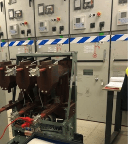
Electrical circuit breakers in front of a control panel; testing equipment attached.

Essential Steps for Commissioning Circuit Breakers

1. Verification of Control Wiring

Meticulously inspect control wiring for correct connections, continuity, and insulation resistance (IR) values. This ensures reliable control circuit operation.

2. Manual Operation

Next, manually operate the breaker to test its functionality. This involves physically operating the breaker to ensure smooth movement and alignment with its intended positions.

3. Power Closing and Operating Tests

Test the breaker's ability to close and open under both manual and electrical operations. This confirms its readiness to handle operational loads and fault currents.

4. Tripping and Closing Time

Measure and record the breaker’s response time. Fast and accurate trip/close timing is essential for minimizing fault duration and improving grid stability.

5. Trip-Free and Anti-Pumping Operation

Verify the trip-free mechanism to ensure the breaker will open during faults even under manual closure attempts. Check anti-pumping to prevent multiple closings during sustained fault conditions.

6. IR Values, Resistance, and Minimum Pickup Voltage

Measure insulation resistance (IR), internal resistance, and minimum pickup voltage. Low IR or abnormal resistance can lead to future insulation breakdowns or overheating.

7. Contact Resistance

Measure contact resistance to confirm low-loss current paths. High resistance at breaker contacts can lead to arcing and excessive heat.

Want to model insulation levels across a system? Learn about our Power System Studies

8. Simultaneous Closing and Mechanical Interlocks

Ensure breakers don’t close simultaneously when interlocked. Mechanical interlocks must be tested to prevent parallel feeds and system shorting.

9. Electrical and Mechanical Interlocks

Verify that electrical and mechanical interlocks function correctly—safeguarding against unsafe switching sequences or unauthorized operation.

10. Spring Charging Motor and Limit Switches

Check the spring charging motor and measure charging time. Also verify limit switch behavior, ensuring accurate open/close positioning and signaling.

11. Current Transformers (CTs)

Confirm proper installation and connection of CTs. Accurate current measurement is critical for protection and coordination.

We assist with transformer integration and metering accuracy in our Utility-Scale Battery Storage Services

12. High Voltage Test

Perform a high voltage withstand test to verify insulation integrity under maximum operating voltages. This prevents insulation failure in live conditions.

13. Functional Tests

Conduct comprehensive functional testing, including checks on:

  • Auxiliary contacts
  • Alarms and signaling
  • Local/remote control
  • Protection coordination
  • Communications (if SCADA integrated)

Conclusion

Commissioning of circuit breakers is not a single-step task—it’s a rigorous, multi-phase process that validates both safety and operational readiness. By performing each step outlined above, engineers ensure compliance, performance, and grid reliability.

Planning NERC-compliant commissioning or protection testing? View our NERC Compliance Services


Trust Keentel for Your Circuit Breaker Commissioning Projects

Keentel Engineering offers professional testing, commissioning, and verification services for medium and high-voltage circuit breakers across utility, BESS, and renewable systems. Whether for new installations or upgrades—we ensure compliance, safety, and performance.


A smiling man with glasses and a beard wearing a blue blazer stands in front of server racks in a data center.

About the Author:

Sandip "Sonny" R. Patel, P.E.

IEEE Senior Member · Founder & CEO, Keentel Engineering

In 1995, Sonny Patel earned his Electrical Engineering degree from the University of Illinois. But degrees don't build legacies — action does.

For three decades, he has worked the power industry from every side of the table: 16 years as a utility engineer at Exelon/Commonwealth Edison; generation leadership across hydroelectric, industrial steam turbine, and a 9 GW renewable fleet; NERC Regional Entity Senior Compliance Engineer and Audit Team Lead, auditing some of the nation's largest utilities; and testing and commissioning lead on equipment up to 765 kV — the very top of the North American grid.Utility. Generator. Regulator. Consultant. Few engineers have seen all four seats. Fewer still have sat in them.

His experience spans nuclear, hydro, conventional generation, renewables, oil and gas, mining — and today's data centers, where he is authoring a three-book series on data center design. He is a Licensed Professional Engineer in six states and a Licensed Electrical Contractor in Florida (Unlimited EC) — he doesn't just design the work; he's qualified to stand behind its execution.Today, as Founder and CEO of Keentel Engineering, Sonny leads a nationwide team of engineers delivering substation design, power system studies, NERC compliance, and commissioning — done right, coast to coast.Three decades. Every side of the table. One standard: accountable engineering.

Four workers in safety vests and helmets stand with arms crossed near wind turbines.

Let's Discuss Your Project

Let's book a call to discuss your electrical engineering project that we can help you with.

Man in a blazer and open shirt, looking at the camera, against a blurred background.

About the Author:

Sandip "Sonny" R. Patel, P.E.

IEEE Senior Member · Founder & CEO, Keentel Engineering

In 1995, Sonny Patel earned his Electrical Engineering degree from the University of Illinois. But degrees don't build legacies — action does.

For three decades, he has worked the power industry from every side of the table: 16 years as a utility engineer at Exelon/Commonwealth Edison; generation leadership across hydroelectric, industrial steam turbine, and a 9 GW renewable fleet; NERC Regional Entity Senior Compliance Engineer and Audit Team Lead, auditing some of the nation's largest utilities; and testing and commissioning lead on equipment up to 765 kV — the very top of the North American grid.

Utility. Generator. Regulator. Consultant. Few engineers have seen all four seats. Fewer still have sat in them.

His experience spans nuclear, hydro, conventional generation, renewables, oil and gas, mining — and today's data centers, where he is authoring a three-book series on data center design. He is a Licensed Professional Engineer in six states and a Licensed Electrical Contractor in Florida (Unlimited EC) — he doesn't just design the work; he's qualified to stand behind its execution.

Today, as Founder and CEO of Keentel Engineering, Sonny leads a nationwide team of engineers delivering substation design, power system studies, NERC compliance, and commissioning — done right, coast to coast.Three decades. Every side of the table. One standard: accountable engineering.

Leave a Comment

Related Posts

PRC-028 PRC-029 and PRC-030 NERC IBR compliance guide
By SANDIP R PATEL • October 3, 2026
Engineering guide to PRC-028 disturbance recording, PRC-029 ride-through and PRC-030 event detection for inverter-based resources.

Keentel Engineering graphic showing damped and undamped subsynchronous oscillations.
By SANDIP R PATEL • October 3, 2026
A practical guide to SSO classification, SSR, PEDI, Wind-SSCI, EMT analysis, mitigation and protection based on CIGRE TB 909.

PV String I-V Curve Testing for Solar Performance Loss
By SANDIP R PATEL • October 3, 2026
Learn how PV string I-V curve testing identifies hidden solar performance losses, including soiling, shading, mismatch, degradation, and wiring faults.

Active harmonic filter reducing VFD current harmonics and grid THDi.
By SANDIP R PATEL • October 3, 2026
Learn how active harmonic filters work, how to size AHF systems, reduce VFD harmonics, calculate losses, and meet IEEE 519 TDD limits at the PCC.
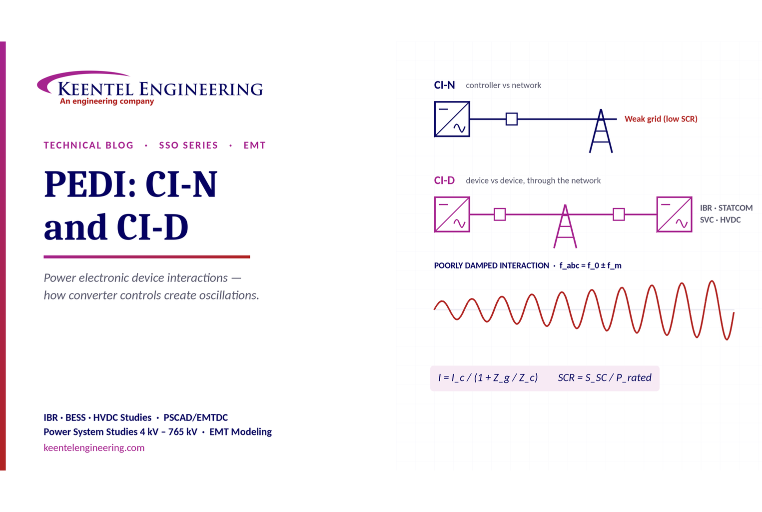
PEDI CI-N and CI-D power system interaction diagram
By SANDIP R PATEL • October 3, 2026
Learn power electronic device interactions (PEDI), including CI-N and CI-D, weak-grid stability, SCR, EMT studies, impedance analysis and mitigation for IBRs.
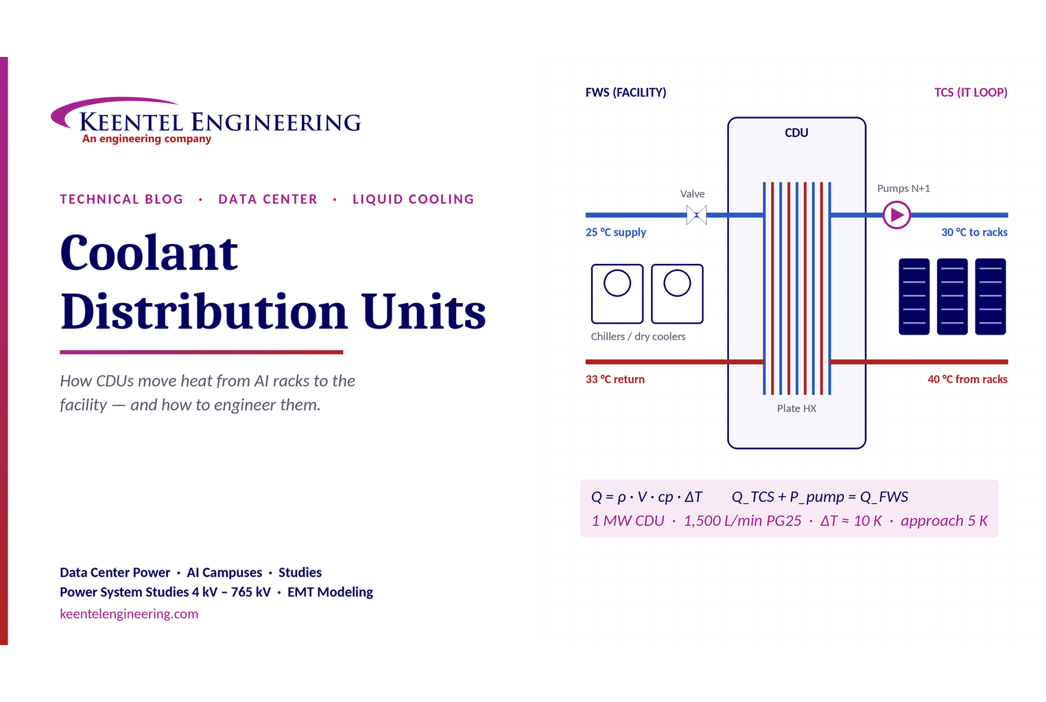
Coolant distribution unit for data center cooling
By SANDIP R PATEL • October 3, 2026
Learn how data center coolant distribution units (CDUs) work, including FWS and TCS loops, heat transfer, sizing, redundancy and liquid cooling for AI data centers.
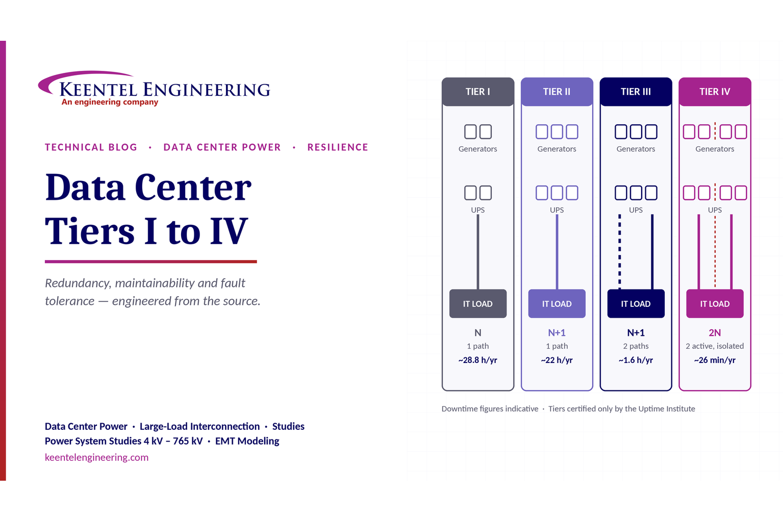
Data Center Tiers I to IV: An Electrical Engineer's Guide to Redundancy, Maintainability and Fault T
By SANDIP R PATEL • October 3, 2026
Compare Data Center Tiers I–IV, including redundancy, uptime, Tier III concurrent maintainability, Tier IV fault tolerance, UPS, generators and power design.

BESS grid stability with frequency response and POI interconnection.
By SANDIP R PATEL • October 3, 2026
Learn how BESS supports grid stability through fast frequency response, voltage support, oscillation damping, black start, grid-forming controls and EMT studies.
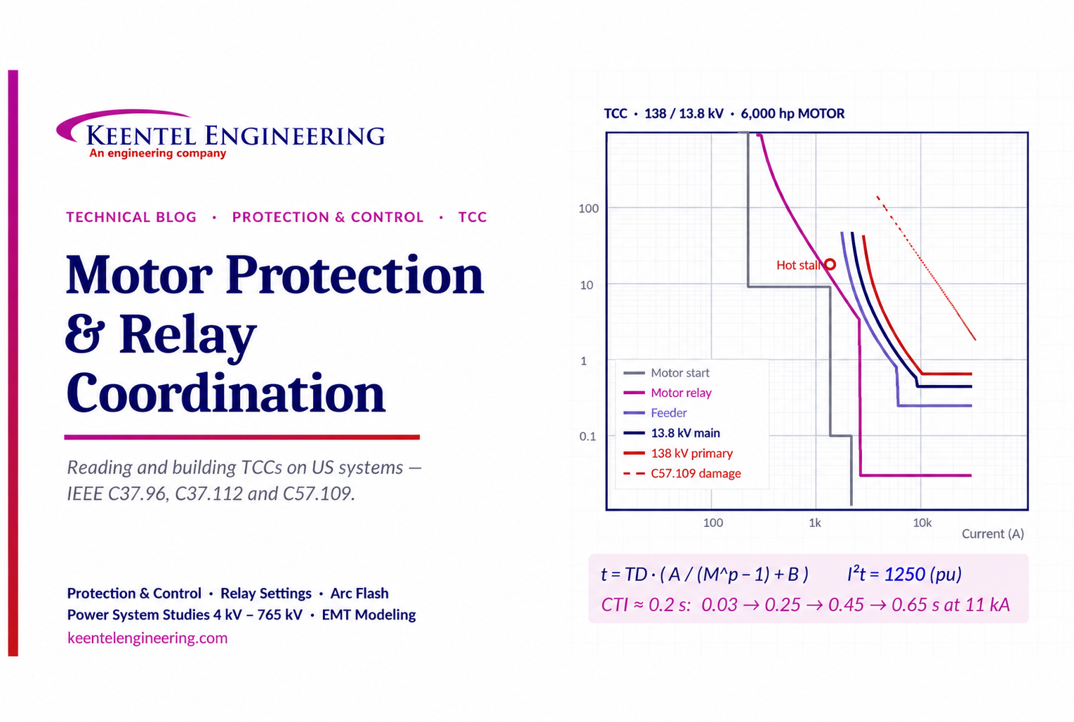
Motor Protection & Relay Coordination TCC Guide
By SANDIP R PATEL • October 3, 2026
Learn motor protection and relay coordination using TCC curves, IEEE standards, transformer damage limits, CTI settings and a 138/13.8 kV example.





