


A Coordinated Electric System Interconnection Review—the utility’s deep-dive on technical and cost impacts of your project.

Enhancing Grid Reliability Through Load Flow and Reactive Power Compensation Studies

Black and white icon of a calendar showing a grid of dates. D

May 16, 2025 | Blog

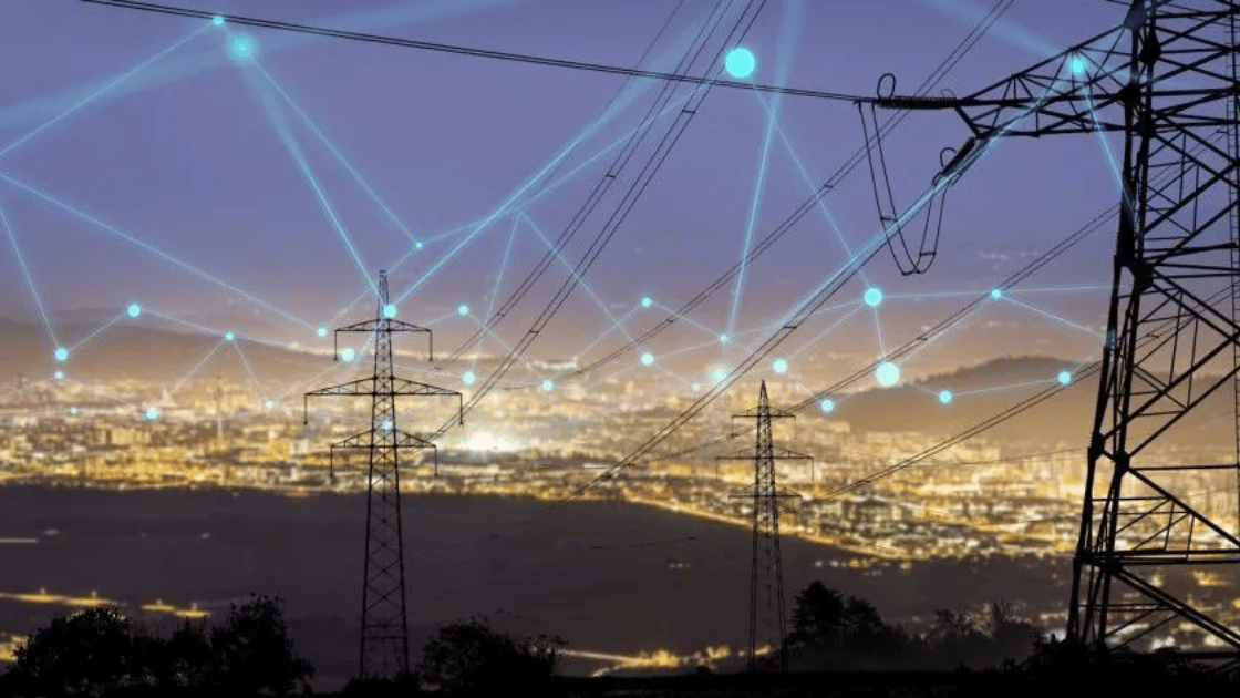
High-voltage power lines and towers over a city at dusk, overlaid with a glowing digital network connection graphic.

Introduction

As power systems evolve with increased renewable integration, load flow studies and reactive power compensation have become essential to maintain grid reliability, operational efficiency, and regulatory compliance. Keentel Engineering delivers advanced load flow and reactive compensation studies to help utilities and developers maintain voltage stability, reduce losses, and meet ANSI/IEEE standards.

A reactive power study helps evaluate voltage control, system efficiency, and optimal placement of compensation devices for reliable grid performance.


What Is a Load Flow and Reactive Compensation Study?

A load flow study evaluates how real (MW) and reactive power (MVAR) flows through a network, measuring voltage levels, power losses, and equipment loading. It ensures that the system can handle varying loads or generation without violating technical constraints.

Reactive compensation involves deploying devices like:

  • Capacitor banks
  • Static Var Compensators (SVCs)
  • Statcoms

These stabilize voltage, improve power factor, and enhance grid efficiency.

These studies ensure compliance with ANSI C84.1 voltage limits 0.95 to 1.05 pu, maintaining acceptable voltage ranges across the network.


Objectives of Load Flow & Reactive Power Studies

  • Ensure Grid Code Compliance and interconnection approval
  • Maintain voltage within ANSI/IEEE thresholds
  • Identify overloaded assets and power loss hotspots
  • Prevent voltage collapse under contingencies
  • Recommend optimal reactive power placement


Maintaining voltage within ANSI C84.1 limits (0.95–1.05 pu) is critical for system reliability and regulatory compliance.


Tools and Methodology

We utilize tools such as ETAP, PSSE, and DIgSILENT PowerFactory to simulate and analyze power system behavior. Methodology includes:

  1. Base Load Simulation
  2. Contingency Analysis (N-1)
  3. Voltage Profile Evaluation
  4. Reactive Compensation Planning

Each study accounts for:


  • Transformer tap settings
  • Load growth forecasts
  • Generator dispatch assumptions
  • Seasonal variations

Confidential Case Studies

Case Study 1: Collector System Undervoltage Fix (34.5 kV)

Issue: Remote nodes at 0.89 pu during solar peak.
Solution: 2 MVAR capacitor bank added.
Result: Voltage improved to 0.98 pu.


Case Study 2: Reactive Compliance at 138 kV Interconnection

Issue: A renewable project failed ISO reactive capability.
Solution: SVC installation.
Result: Maintained 0.95–1.05 pu voltage band.


Case Study 3: Post-Contingency Voltage Collapse Prevention

Issue: Transformer outage caused unacceptable dips.
Solution: STATCOM recommended and validated in dynamic models.


Case Study 4: Transformer Overload Resolution

Issue: 110% transformer loading.
Solution: Compensation rerouting via feeders.
Result: Loading reduced to 92%.


Case Study 5: Reactive Exchange Mitigation

Issue: Excessive reactive export during off-peak hours.
Solution: Control system for capacitor switching.
Result: Achieved near net-zero reactive exchange.


Why Keentel Engineering?

Keentel Engineering provides end-to-end power system study solutions, from feasibility to design and commissioning support. Our engineers ensure your system meets interconnection standards and operates efficiently across all scenarios.


Keentel Engineering aligns its studies with IEEE standards and evolving industry guidelines, including IEEE 2842-2022 for advanced system performance evaluation.


Conclusion

Conducting a thorough load flow and reactive compensation study is essential to maintaining voltage stability, grid reliability, and compliance with interconnection requirements. These studies offer invaluable insights for planners, developers, and utilities as they navigate the evolving power grid landscape. Integrating proper compensation devices not only enhances operational performance but also ensures long-term economic and technical viability.

Accurate load flow and reactive power studies ensure long-term grid stability, efficient operation, and compliance with modern standards.


Frequently Asked Questions – Load Flow & Reactive Power Studies

1. Why is reactive compensation important in load flow studies?

Reactive compensation ensures voltage stability, minimizes losses, and enables efficient power delivery by maintaining a balanced power factor and preventing voltage drops.

2. What tools are typically used for reactive compensation studies?

Common tools include ETAP, PSSE, DIgSILENT PowerFactory, and ASPEN OneLiner, depending on the complexity and grid requirements.

3. What voltage limits are typically considered acceptable in such studies?

Voltage limits are usually maintained between 0.95 pu to 1.05 pu per ANSI C84.1 and IEEE 519 standards.

4. What is the difference between static and dynamic reactive power compensation?

Static compensation (e.g., capacitor banks) offers fixed or stepped support, while dynamic compensation (e.g., STATCOM, SVC) responds rapidly to voltage changes.

5. How are transformer tap positions handled during load flow simulations?

Taps are either fixed based on system design or set to automatic (AVR mode) to simulate voltage regulation under different loading conditions.

6. Can load flow studies detect harmonic distortions?

No, load flow studies analyze steady-state power flows. Harmonic studies are separate and involve frequency-domain simulations.

7. How often should these studies be updated?

Annually for critical facilities or upon significant changes such as new generator additions, load increases, or grid upgrades.

8. Is reactive power exchanged with the grid penalized?

In many ISO/RTO jurisdictions, reactive power exchanges outside the deadband may lead to penalties or charges if not within prescribed interconnection agreements.

9. Can capacitor banks cause issues?

Yes, if not properly sized or coordinated, they can lead to overvoltage, resonance, or switching transients.

10. What happens if the system is undercompensated?

Undervoltage, increased losses, power factor penalties, and even voltage collapse can occur under severe reactive deficiency conditions.

Need Expert support?


A smiling man with glasses and a beard wearing a blue blazer stands in front of server racks in a data center.

About the Author:

Sandip "Sonny" R. Patel, P.E.

IEEE Senior Member · Founder & CEO, Keentel Engineering

In 1995, Sonny Patel earned his Electrical Engineering degree from the University of Illinois. But degrees don't build legacies — action does.

For three decades, he has worked the power industry from every side of the table: 16 years as a utility engineer at Exelon/Commonwealth Edison; generation leadership across hydroelectric, industrial steam turbine, and a 9 GW renewable fleet; NERC Regional Entity Senior Compliance Engineer and Audit Team Lead, auditing some of the nation's largest utilities; and testing and commissioning lead on equipment up to 765 kV — the very top of the North American grid.

Utility. Generator. Regulator. Consultant. Few engineers have seen all four seats. Fewer still have sat in them.His experience spans nuclear, hydro, conventional generation, renewables, oil and gas, mining — and today's data centers, where he is authoring a three-book series on data center design. He is a Licensed Professional Engineer in six states and a Licensed Electrical Contractor in Florida (Unlimited EC) — he doesn't just design the work; he's qualified to stand behind its execution.Today, as Founder and CEO of Keentel Engineering, Sonny leads 51 engineers delivering substation design, power system studies, NERC compliance, and commissioning — done right, coast to coast.Three decades. Every side of the table. One standard: accountable engineering

Four workers in safety vests and helmets stand with arms crossed near wind turbines.

Let's Discuss Your Project

Let's book a call to discuss your electrical engineering project that we can help you with.

Man in a blazer and open shirt, looking at the camera, against a blurred background.

About the Author:

Sandip "Sonny" R. Patel, P.E.

IEEE Senior Member · Founder & CEO, Keentel Engineering

In 1995, Sonny Patel earned his Electrical Engineering degree from the University of Illinois. But degrees don't build legacies — action does.

For three decades, he has worked the power industry from every side of the table: 16 years as a utility engineer at Exelon/Commonwealth Edison; generation leadership across hydroelectric, industrial steam turbine, and a 9 GW renewable fleet; NERC Regional Entity Senior Compliance Engineer and Audit Team Lead, auditing some of the nation's largest utilities; and testing and commissioning lead on equipment up to 765 kV — the very top of the North American grid.Utility. Generator. Regulator. Consultant. Few engineers have seen all four seats. Fewer still have sat in them.His experience spans nuclear, hydro, conventional generation, renewables, oil and gas, mining — and today's data centers, where he is authoring a three-book series on data center design. He is a Licensed Professional Engineer in six states and a Licensed Electrical Contractor in Florida (Unlimited EC) — he doesn't just design the work; he's qualified to stand behind its execution.Today, as Founder and CEO of Keentel Engineering, Sonny leads 51 engineers delivering substation design, power system studies, NERC compliance, and commissioning — done right, coast to coast.Three decades. Every side of the table. One standard: accountable engineering

Leave a Comment

Related Posts

12.47 kV pole-mounted distribution transformer assembly designed for U.S. IEEE and NESC utility stan
By SANDIP R PATEL August 20, 2026
Learn U.S. pole-mounted transformer design requirements, including IEEE, ANSI, and NESC standards, voltage classes, grounding, protection, and DER considerations.
PRC-023-6 BESS relay loadability compliance guide
By SANDIP R PATEL August 19, 2026
Understand PRC-023-6 for utility-scale BESS: applicability, the 39-month rule, relay loadability, setting criteria, Category 2 IBRs, and audit evidence.
PRC-029-1 voltage ride-through envelope for inverter-based resources.
By SANDIP R PATEL August 18, 2026
Learn PRC-029-1 compliance requirements for inverter-based resources, including voltage and frequency ride-through, EMT studies, protection settings, and testing.
Solar plant electrical testing and commissioning for utility-scale PV systems
By SANDIP R PATEL August 17, 2026
A technical guide to solar plant electrical testing, commissioning, I-V curves, thermography, insulation testing, cable tests and performance acceptance.
Alt Text: Gas-insulated substation engineering guide covering GIS safety, reliability, VFTO, partial
By SANDIP R PATEL August 16, 2026
Explore GIS substation engineering, including design, SF6 safety, VFTO, grounding, commissioning, testing, GIS vs AIS, and IEEE/IEC standards.
Cable testing before energization engineering guide
By SANDIP R PATEL August 16, 2026
Learn the correct cable testing sequence before energization, including VLF, AC/DC withstand, sheath testing, partial discharge, tan delta, and standards.
substation drawing sets
By SANDIP R PATEL August 16, 2026
Explore how substation drawing sets are developed, reviewed and controlled through engineering studies, design milestones, QA/QC and final construction release.
Grid-forming vs grid-following BESS inverters
By SANDIP R PATEL August 15, 2026
Compare grid-forming vs grid-following BESS inverters, control loops, weak-grid stability, protection, compliance, and interconnection study impacts.
MOD-025 and MOD-026 post-COD verification testing with PSS E and PSCAD dynamic model validation
By SANDIP R PATEL August 15, 2026
Learn MOD-025 and MOD-026 post-COD requirements for generator capability verification, PSS®E and PSCAD model validation, IBR testing, and NERC compliance.