


Learn how transmission line design progresses from 30% to IFC, covering clearance, sag-tension, structures, foundations, and engineering best practices.
Learn how the AP1000 supply chain, combined operating licenses, nuclear grid interconnection, transmission planning, and power system studies. for success.
Learn how to automate PSS®/E with Python for power system studies, API scripting, result extraction, and scalable interconnection workflows.
Learn CenterPoint Energy's interconnection requirements for large data center loads, including primary service, harmonic analysis, emergency generation, protection, and engineering compliance.
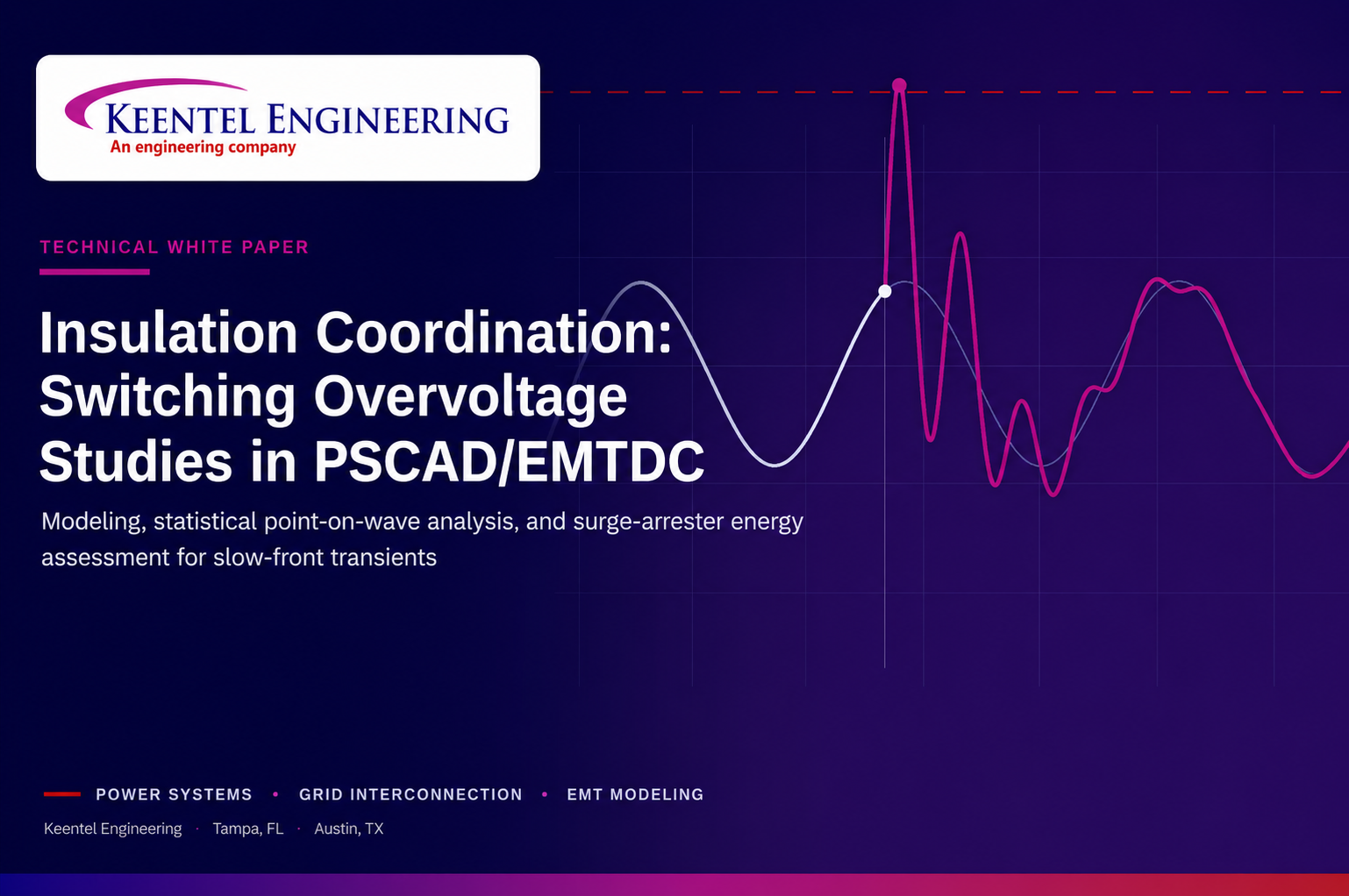
Learn how switching overvoltage studies, insulation coordination, surge arrester assessment, and PSCAD/EMTDC modeling protect EHV systems.
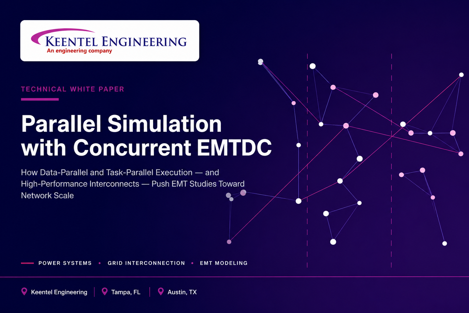
Learn how Concurrent EMTDC uses data parallelism, task parallelism, PSCAD, and high-performance interconnects to accelerate EMT simulation studies.

Learn the complete substation electrical design process, including 30%, 60%, 90%, and IFC deliverables, engineering reviews, grounding, protection, and interconnection requirements.
FERC accepted PJM's Expedited Interconnection Track on June 9, 2026. Learn the eligibility rules, financial requirements, state siting commitment, and engineering checklist for the 10-month fast lane to a signed GIA.
Estimate interconnection costs before entering the queue. Learn how network upgrade costs, POI costs, and feasibility studies impact project success.


