
A Coordinated Electric System Interconnection Review—the utility’s deep-dive on technical and cost impacts of your project.
Challenge: Frequent false tripping using conventional electromechanical relays
Solution: SEL-487E integration with multi-terminal differential protection and dynamic inrush restraint
Result: 90% reduction in false trips, saving over $250,000 in downtime
ERCOT enforces all of the above through simulation, which means your model is your compliance case. The bar is now high:
- Whole-facility scope. The model must represent everything the IT load, the UPS and power conversion, the cooling plant, the protection and control systems in formats compatible with ERCOT's study platforms (PSS/E, PSCAD, TSAT).
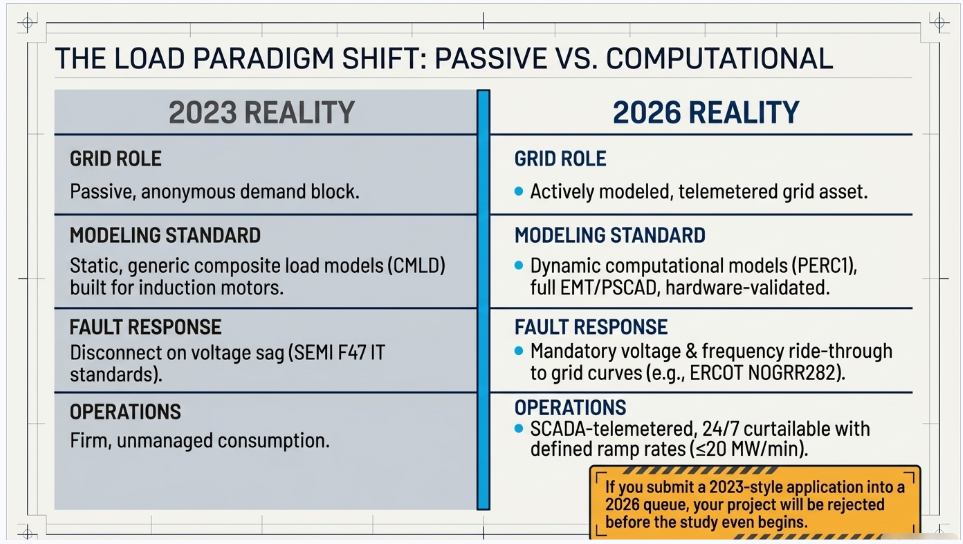
- Real control loops, not approximations. Generic textbook representations are unacceptable. The model must capture the actual inner control behavior of your power electronics.
- Hardware-validated converter models. For electronic loads, the PSCAD model must be benchmarked against actual hardware testing including voltage ride-through and subsynchronous response. A model assembled from standard PSCAD library blocks fails by definition, because a generic block has never been tested against your vendor's hardware. The good news: validation is a hardware-type test, so results for a given converter product are reusable across every facility that uses it.
- Format migration. Facilities that previously submitted the older composite load model (CMLD) format must transition to EPRI's PERC1 format.
- Three checkpoints. Models are reviewed before the stability study begins (no model, no study), before each quarterly stability assessment, and for electronic loads one final time before energization, when you must submit as-built models with a documented comparison against the previously studied data and a sworn attestation that the model matches actual field settings. ERCOT's review takes 10 business days, extendable by 20 put it on your critical path.
- A living obligation. Change your technology, controls, or relay settings in a way that affects ride-through including converting a crypto mining site to an AI data center — and you've triggered a new interconnection study, even if your megawatts don't change.
| Parameter | Detail |
|---|---|
| System | 230 kV / 138 kV transmission corridors, wind and wet-snow icing exposure |
| Data basis | 15 years of minute-resolution forced-outage records + regional weather observations |
| Core methods | Event grouping, MVA performance curves, time-to-95%-restore, area outage rate curves, fragility modeling, rerun-history benefits, exceedance and log-domain risk metrics |
| Headline result | ≈85% of maximum resilience benefit at 60% of original capital; worst-event restoration window cut from 11 days to 5 in rerun-history terms |
| Decision supported | Capital portfolio selection; resilience plan filing; post-investment verification framework |
| System / Topic | Governing Standard(s) | What It Controls |
|---|---|---|
| Overall plant electrical distribution | IEEE 141 (Red Book); IEEE 666 | Distribution architecture, voltage selection, design of generating station auxiliary service systems |
| Power system studies | IEEE 399 (Brown Book); IEEE 551 | Load flow, symmetrical/asymmetrical short circuit, motor starting methodologies down to the lowest LV panelboard |
| Protection & coordination | IEEE 242 (Buff Book); IEEE 3004.5; IEEE C37 series | Generator relaying (21, 59N, 87G), time-current coordination, selective clearing between LV and MV tiers |
| GSU / UAT / SST transformers | IEEE C57.12.00 and C57 family | Transformer ratings, impedance, testing, loading |
| HV switchyard breakers | IEEE C37.06 | AC high-voltage circuit breaker preferred ratings |
| MV switchgear (13.8 kV) | IEEE C37.20.2; IEEE C37.20.7 | Metal-clad construction, compartmentalization, vacuum breakers; arc-resistant design with plenum venting |
| MV cable | UL 1072; ICEA S-93-639 (NEMA WC 74) | Type MV-105 shielded cable, 133% insulation level for HRG systems |
| LV switchgear (480 V) | IEEE C37.13; UL 1558 | Metal-enclosed LV power circuit breaker switchgear to 635 V, draw-out ACBs with electronic trip units |
| Motor control centers | UL 845; NEMA ICS 18 | LV-MCC construction, MCCB/MCP protection for motors under ~200 HP |
| Motors | NEMA MG-1 | Motor performance, starting characteristics, service factors |
| DC & battery systems | IEEE 485; IEEE 946 | Lead-acid battery sizing (125/250 VDC), DC auxiliary system design |
| Grounding | IEEE 80; IEEE 142 (Green Book) | Ground grid step/touch potential limits; system grounding including high-resistance grounding |
| Lightning protection | IEEE 998 | Direct-stroke shielding of switchyard and outdoor generator structures |
| Arc flash & electrical safety | IEEE 1584; NFPA 70E | Incident energy calculation; worker safety boundaries and PPE |
| Fire protection | NFPA 850 | Fire protection and risk management for combustion turbine generating plants |
| Installation code | NEC (NFPA 70); NESC | Wiring methods inside the plant fence; overhead/outdoor clearances at the switchyard |
| Interconnection & compliance | FERC LGIP; NERC MOD-025/026/027, PRC-019/024/029, FAC-008 | Interconnection process, model validation, protection/ride-through coordination, facility ratings |
| IFC / Construction Deliverable | Purpose |
|---|---|
| Stamped IFC packages | Legal basis for construction; P.E. responsible charge |
| Final relay settings & TCCs | Protection as-installed matches the coordination study |
| Calculation archive | Owner records; NERC audit evidence trail |
| Commissioning procedures | Safe, sequenced energization; MOD field testing |
| Construction support | RFIs, field changes, FAT/SAT witness |
| As-builts & model handoff | Operating baseline; future study currency |
| Metric | Outcome |
|---|---|
| Defects found pre-occupancy | Three topology defects and one settings-mismatch family corrected before load migration; the shared-switchboard defect alone would have invalidated the concurrently-maintainable claim on day one |
| IST findings | Fourteen additional discrepancies surfaced under scenario testing (control logic, alarm mapping, one generator sequencing fault) — all closed before handover instead of during operations |
| Black-building test | Passed on second execution; the first attempt exposed the generator sequencing fault under true block load, exactly the failure the compressed plan would never have found |
| Handover quality | Operations team certified on the actual failure scenarios; corrected EOPs and settings documentation delivered as controlled documents |
| Business outcome | Occupancy proceeded three weeks behind the original date — against an independent estimate that the uncorrected sequencing fault carried a high probability of a full facility outage within the first year |
The Complete 2026 Guide to POI Interconnection for Large Loads and Data Centers
Aug 20, 2026 | Blog
Prepared by Keentel Engineering | Power System & Substation Engineering | Tampa · Austin · Sacramento · Baltimore
How to Use This Guide
This is a working reference for data center developers, hyperscalers, colocation providers, industrial load owners, site selection teams, EPC contractors, and the attorneys and financiers who back them. It answers, in order:
- What changed in 2025–2026 and why your 2023 interconnection playbook is obsolete
- Who the U.S. grid operators are, where their rules live, and how to reach them
- How a large load actually connects in each region — because the process is different in all seven ISO/RTOs and different again outside them
- What an electrical power engineering firm produces for you: drawings, studies, models, reports
- Exactly what data you must hand your engineer before real work can start
- What it costs, how long it takes, and where projects die
The final third is a 60-question FAQ. If you are in a hurry, read Part 1, the threshold table in Part 4, the client checklist in Part 7, and the FAQ.
A word on shelf life
Large load interconnection rules in the United States are being rewritten right now, in nearly every region, simultaneously. FERC issued show-cause orders to all six RTO/ISOs on June 18, 2026; responses were due August 17, 2026. NERC must file mandatory reliability standards for computational loads by December 31, 2026. Texas paused its data center interconnection queue on August 3, 2026. Anything written in this space has a shelf life measured in months, not years. Treat every rule citation here as a pointer to a primary source — and verify against the current tariff before you commit capital. Keentel maintains updated regional briefs; contact us for the current version.
PART 1 — WHAT CHANGED, AND WHY IT MATTERS TO YOUR PROJECT
1.1 The event that rewrote the rulebook
On July 10, 2024, a lightning arrester failed on a 230 kV line in Northern Virginia. What followed was six faults in 82 seconds. No utility equipment tripped the load. Instead, approximately 1,500 MW of data center load disconnected itself — voltage at those sites dipped to roughly 0.25–0.40 per unit, and customer-side protection and control logic took the facilities off the grid. About 1,260 MW stayed off for hours.
NERC's incident review traced the sustained loss to an interaction nobody had modeled: the automatic reclosing sequence on the faulted line produced repeated voltage dips, and the data centers' UPS control schemes counted those dips. Three disturbances inside one minute, and the facilities transferred to backup power and stayed there.
That single event is the most cited technical fact in the entire large-load reliability debate. It is why your ride-through settings are now a negotiated term in your interconnection agreement, why the grid operator wants a dynamic model of your load, and why "we'll figure out the electrical details later" is no longer a viable project strategy.
Source: NERC, Incident Review: Simultaneous Voltage-Sensitive Load Loss (January 8, 2025).
1.2 The regulatory cascade, 2025 to today
| Date | Action | What it means for you |
|---|---|---|
| Jun 20, 2025 | Texas SB6 signed | Curtailment equipment mandatory for ERCOT large loads interconnected after Dec 31, 2025; ERCOT "kill switch" for co-located load; $100,000 minimum screening study fee; duplicate-request disclosure |
| Aug 1, 2025 | ERCOT NPRR1234 / PGRR115 effective | First formal ERCOT large load interconnection study regime; ≥75 MW triggers a study, ≥25 MW triggers modeling data |
| Nov 14, 2025 | ERCOT NOGRR282 / NPRR1308 initial compliance | Mandatory voltage and frequency ride-through curves for Large Electronic Loads |
| Oct 23, 2025 | DOE directs FERC to open a large load interconnection rulemaking | Becomes FERC Docket RM26-4; working definition of large load >20 MW |
| Jan 14, 2026 | FERC approves SPP's HILL process (ER26-247) | The first fully tariffed, RTO-run large load interconnection process in the U.S. |
| Jan 16, 2026 | PJM Board issues Large Load Additions decision letter | Five-pillar program: forecasting reform, bring-your-own-generation, Connect and Manage, reliability backstop, market review |
| Feb 12, 2026 | NY PSC Case 26-E-0045 opened | New York large load interconnection reform; DPS staff white paper due Feb 12, 2027 |
| Mar 13, 2026 | FERC approves SPP's Consolidated Planning Process | Merges generator interconnection with transmission planning; target GIA in 10 months vs 51-month historical median |
| May 4–8, 2026 | NERC Level 3 "Essential Action" Alert on computational loads | NERC's highest and most critical alert. Seven mandatory actions on modeling, studies, commissioning, protection, fault recording, and operational communication. Responses were due August 3, 2026 |
| Jun 5, 2026 | NERC Reliability Guideline: Risk Mitigation for Emerging Large Loads | The technical playbook: PSPD dynamic models for all large loads, EMT where the grid is weak, model attestation, ramp rate disclosure |
| Jun 9, 2026 | FERC approves PJM's Expedited Interconnection Track (ER26-1563) | Fast lane for ≥250 MW UCAP generation paired with large load; operational August 2026, sunsets end of 2027 |
| Jun 18, 2026 | FERC issues $206 show-cause orders to all six RTO/ISOs | PJM EL26-67, SPP EL26-68, NYISO EL26-69, MISO EL26-70, CAISO EL26-71, ISO-NE EL26-72 |
| Jun 18, 2026 | FERC order on PJM co-located load (EL25-49-002) | Three new transmission services: NITS, Firm Contract Demand, Non-Firm Contract Demand. 50 MW threshold. Ancillary services on gross demand |
| Jun 18, 2026 | PUCT approves ERCOT Batch Zero (PGRR145/NPRR1325) | Effective July 11, 2026. One-time transitional study to clear a 400+ GW backlog |
| Jul 11, 2026 | ERCOT Planning Guide Section 9 effective | "Large Load Interconnection or Modification" — the operative ERCOT rule section |
| Jul 16, 2026 | FERC orders NERC to write mandatory standards for computational loads (RD26-7) | Phase I filing due Dec 31, 2026. Data centers may become NERC-registered entities for the first time |
| Jul 31, 2026 | PJM files Reliability Backstop Procurement (ER26-3380) | 6,831.3 MW UCAP initial target, up to 15-year terms, $555/MW-day cap |
| Aug 3, 2026 | Texas Governor directs audit of all ERCOT data center interconnection requests | ERCOT suspends the Batch Zero classification deadline. Projects failing audit "must be denied" |
| Aug 17, 2026 | RTO/ISO show-cause responses due | Several RTOs sought 90-day abeyances; verify current status |
1.3 The five things FERC told every RTO to fix
Every one of the six show-cause orders issued June 18, 2026 demands the same five categories of reform. Understanding these tells you where every region is heading, regardless of where it is today:
1. A real application and study process. Rolling acceptance of requests, a non-refundable application fee, escalating readiness milestones (deposits and site control), and studies completed in 60 to 90 days. Studies must evaluate rapid ramp-up, demand variability, cumulative regional impact, and alternative transmission technologies — not just the traditional "build a bigger wire" answer.
2. Cost transparency and protection against cost shifting. A publicly searchable database of large load additions by pricing zone. Published network upgrade cost estimates. Pro forma cost recovery agreements with minimum customer contributions and financial security.
3. Clear rules for co-location and behind-the-meter generation. Three new transmission services — interim non-firm network service during construction, Firm Contract Demand, and Non-Firm Contract Demand. Ancillary services charged on gross, not net, demand.
4. Real services for flexible load. Loads that accept operational limits get faster access and smaller network upgrades. This is the single largest schedule lever available to a developer.
5. Fast-track interconnection for generation electrically proximate to a large load. Generation within roughly two substations of the load gets an accelerated path, including load-limited service with no injection to the transmission system.
The strategic read: the era of a data center being a passive, anonymous, price-taking block of demand is over. In every region in the country, a large load is becoming a studied, modeled, telemetered, curtailable, cost-responsible grid asset — much closer to how a generator is treated. Plan your project accordingly.
1.4 FERC's proposed definitions (the emerging national baseline)
- Large Load — a new commercial or industrial customer at a single site with peak load ≥50 MW, interconnecting above 69 kV, not part of a co-location arrangement.
- Co-Located Load — end-use load physically connected to an existing or planned generating facility, on the interconnection customer's side of the POI.
- Eligible Load — co-located load and/or load served by behind-the-meter generation.
- Flexible Large Load — a large load willing to limit energy withdrawals under specified system conditions.
- Electrically Proximate Large Load — load no more than two substations from the generating facility.
- Computational Load (FERC/NERC, RD26-7) — power demand from IT equipment: servers, storage, networking. Covers data centers, AI training facilities, and cryptocurrency mining.
PART 2 — THE U.S. GRID OPERATOR MAP
2.1 The seven ISOs and RTOs
The continental United States is served by seven Independent System Operators / Regional Transmission Organizations covering roughly two-thirds of U.S. electricity demand. The remaining third — most of the Southeast, most of the non-California West, and Alaska/Hawaii — is served by vertically integrated utilities operating their own balancing authorities under FERC Open Access Transmission Tariffs (or, for municipal and federal entities, under their own board-approved rules).
| Operator | Footprint | Website | Interconnection landing page |
|---|---|---|---|
| PJM Interconnection | 13 states + DC: DE, IL, IN, KY, MD, MI, NJ, NC, OH, PA, TN, VA, WV | pjm.com | pjm.com/planning |
| MISO (Midcontinent ISO) | 15 states + Manitoba: AR, IL, IN, IA, KY, LA, MI, MN, MS, MO, MT, ND, SD, TX (part), WI | misoenergy.org | misoenergy.org/planning |
| ERCOT | ~90% of Texas | ercot.com | ercot.com/services/rq/large-load-integration |
| CAISO (California ISO) | Most of CA + part of NV; WEIM/EDAM footprint spans the West | caiso.com | caiso.com/generation-transmission |
| SPP (Southwest Power Pool) | 14 states: AR, IA, KS, LA, MN, MO, MT, NE, NM, ND, OK, SD, TX (part), WY | spp.org | spp.org/engineering |
| NYISO | New York State | nyiso.com | nyiso.com/interconnections |
| ISO-NE (ISO New England) | CT, MA, ME, NH, RI, VT | iso-ne.com | iso-ne.com/system-planning |
2.2 Key resources by operator
PJM Interconnection
| Resource | Where |
|---|---|
| Open Access Transmission Tariff (OATT) | agreements.pjm.com/oatt |
| Manuals library | pjm.com/library/manuals |
| M14H — New Service Requests Cycle Process | pjm.com/-/media/DotCom/documents/manuals/m14h.pdf |
| M14B — RTEP Process; M14C — Interconnection Construction; M14G — Generation Interconnection | same manuals library |
| Applications & forms (model submission hub) | pjm.com/planning/service-requests/application-and-forms |
| NextGen interconnection portal | nextgen.pjm.com |
| Planning Center / QueuePoint | planningcenter.pjm.com |
| CIFP-LLA committee (large load additions) | pjm.com/committees-and-groups/cifp-lla |
| Dynamic Model Development Guidelines | pjm.com/-/media/DotCom/planning/services-requests/pjm-dynamic-model-development-guidelines.pdf |
| EMT Model Development Guidelines | pjm.com/-/media/DotCom/planning/services-requests/pjm-emt-model-development-guidelines.pdf |
| Load forecast development process | pjm.com/planning/resource-adequacy-planning |
Stakeholder bodies to watch: CIFP-LLA, Load Analysis Subcommittee (LAS), Markets & Reliability Committee (MRC), Planning Committee (PC).
MISO
| Resource | Where |
|---|---|
| Large Load Additions hub | misoenergy.org/planning/large-loads--container-page/large-load-additions |
| Large Load Interconnection Reliability Requirements | misoenergy.org/engage/MISO-Dashboard |
| Generator Interconnection | misoenergy.org/planning/resource-utilization/generator-interconnection |
| Business Practice Manuals (BPM-015 is the GI manual) | misoenergy.org/legal/rules-manuals-and-agreements/business-practice-manuals |
| Tariff Attachment X — Generator Interconnection Procedures | docs.misoenergy.org/ |
| MTEP (transmission expansion plan) | misoenergy.org/planning/transmission-planning/mtep |
| Planning Modeling Manual (MOD-032 data requirements) | cdn.misoenergy.org |
| ERAS Informational Guide | cdn.misoenergy.org |
| Stakeholder feedback portal | misoenergy.org/engage/stakeholder-feedback |
Stakeholder bodies: Large Load Working Group (LLWG) — the dedicated forum; Planning Advisory Committee (PAC); Interconnection Process Working Group (IPWG); Reliability Subcommittee (RSC). MISO also runs quarterly Large Load Additions Workshops.
SPP
| Resource | Where |
|---|---|
| HILL Integration hub (High Impact Large Load) | spp.org/markets-operations/high-impact-large-load-hill-integration |
| Generator Interconnection | spp.org/engineering/generator-interconnection |
| DISIS Manual | opsportal.spp.org/documents/studies |
| Consolidated Planning Process Manual | spp.org |
| HILL Fault Ride-Through Requirements v1.0 | spp.org/documents |
| EMT Model Requirements | opsportal.spp.org/documents/studies |
| Study status postings | opsportal.spp.org/Studies/Gen |
Contacts: GIstudies@spp.org; SPP Request Management System (RMS). Stakeholder bodies: MOPC, Generator Interconnection Advisory Group (GIAG), Regional Tariff Working Group.
ERCOT
| Resource | Where |
|---|---|
| Large Load Integration (the operative hub) | ercot.com/services/rq/large-load-integration |
| Planning Guide — current sections | ercot.com/mktrules/guides/planning/current |
| Section 9 — Large Load Interconnection or Modification | via the Planning Guide page |
| Section 5 — Generator Interconnection; Section 6 — Data/Modeling | same |
| Large Load Working Group (LLWG) | ercot.com/committees/tac/llwg |
| Dynamics Working Group (DWG) — hosts the Large Load Survey | ercot.com/committees/ros/dwg |
| NOGRR282 (ride-through) issue page | ercot.com/mktrules/issues/NOGRR282 |
| Batch Zero submissions | BatchZero@ercot.com |
| Large load interconnection inbox | LargeLoadInterconnection@ercot.com |
Note: ERCOT is not FERC-jurisdictional for transmission rates and interconnection. Its rules come from ERCOT protocols/guides approved by the PUCT. Texas legislation (SB6) sits on top.
CAISO / California
| Resource | Where |
|---|---|
| CAISO Large Loads page | caiso.com/generation-transmission/load/large-loads |
| Large Loads stakeholder initiative | stakeholdercenter.caiso.com/StakeholderInitiatives/Large-loads |
| CAISO tariff | caiso.com/legal-regulatory/tariff |
| Business Practice Manuals | caiso.com/legal-regulatory/business-practice-manuals |
| Generator interconnection (GIDAP, Appendix DD) | caiso.com/generation-transmission/generation/generator-interconnection |
| EMT Modeling Requirements | caiso.com/Documents |
| MOD-032 submittal requirements | caiso.com/library |
| PG&E Electric Rule 30 — transmission-level retail service, 50–230 kV | pge.com/tariffs |
| CPUC Rule 21 (generation interconnection — not the load pathway) | cpuc.ca.gov/Rule21 |
NYISO
| Resource | Where |
|---|---|
| Interconnection landing page | nyiso.com/interconnections |
| OATT Attachment P — Transmission Interconnection Procedures | nyiso.com/documents |
| OATT Attachment HH — Standard Interconnection Procedures (generation cluster process) | NYISO etariff viewer |
| Manual 23 — Transmission Expansion & Interconnection (TEI) Manual | nyiso.com/documents |
| Load & Capacity Data Report ("Gold Book") | nyiso.com/load-capacity-data-report-gold-book |
| Power Trends / System & Resource Outlook | nyiso.com/power-trends- nyiso.com/planning |
| NY PSC Case 26-E-0045 (large load interconnection reform) | documents.dps.ny.gov |
ISO New England
| Resource | Where |
|---|---|
| Transmission, Markets and Services Tariff (incl. §I.3.9) | iso-ne.com/participate/rules-procedures/tariff |
| Proposed Plan Applications | iso-ne.com/system-planning/transmission-planning/proposed-plan-applications |
| PPS-1 — Review of Proposed Plans | iso-ne.com/static-assets/documents/rules_proceds/isone_plan/pp05_1 |
| PPS-3 — Conducting and Evaluating PPA Analyses | same directory, pp05_3 |
| PPS-6 — Interconnection Planning Procedure (generation and ETUs) | same directory, pp05_6 |
| Interconnection Request Technical Data Submittal Guidance | iso-ne.com/static-assets/documents |
| Interconnection Process Guide | iso-ne.com/participate/applications-status-changes/interconnection-process-guide |
| Planning Advisory Committee (PAC) | iso-ne.com/committees/planning/planning-advisory |
| CELT Report / system forecasting | iso-ne.com/system-planning/system-forecasting |
Contact for modeling versions: irtt@iso-ne.com
Federal and reliability bodies
| Body | Role | Where |
|---|---|---|
| FERC | Jurisdiction over transmission service, interconnection, and RTO tariffs (except ERCOT) | ferc.gov · ferc.gov/rm26-4 |
| NERC | Mandatory reliability standards; the Large Loads Action Plan and Level 3 Alert | nerc.com/initiatives/large-loads-action-plan |
| WECC | Regional Entity for the Western Interconnection; base cases, Data Preparation Manual, Anchor Data Set | wecc.org |
| SERC, RF, MRO, NPCC, Texas RE | The other Regional Entities | nerc.com |
| DOE / EIA | Wholesale market overview, national data | eia.gov/electricity/wholesalemarkets |
2.3 The regions with no ISO
If your site is in the Southeast (Southern Company, TVA, Duke Carolinas, Dominion South Carolina, Florida utilities), the Intermountain West (PacifiCorp, Idaho Power, NV Energy, Arizona Public Service, Public Service Co. of Colorado, NorthWestern), the Northwest (BPA, Portland General, Puget Sound Energy, Avista), or on a municipal or federal system (Salt River Project, LADWP, Imperial Irrigation District, NYPA, LIPA, Nebraska public power), there is no regional interconnection queue for load. You connect through the individual transmission provider:
- Retail large load served by a vertically integrated utility — you connect under the utility's state-approved retail tariff and line-extension rules, increasingly supplemented by a purpose-built large load tariff (see the table in Part 3.8).
- Wholesale arrangement — the serving entity takes Network Integration Transmission Service or Point-to-Point service under the transmission provider's OATT, and your physical connection is added as a new Point of Delivery (POD).
- BPA — the Line and Load Interconnection (LLI) process governs new or modified Points of Delivery on the Federal Columbia River Transmission System. Submit a signed LLIR form to interconnection@bpa.gov with "LLIR" in the subject; requests sent anywhere else are not queued.
- Non-jurisdictional entities (SRP, LADWP, IID, most munis and co-ops) — their own board-approved rules govern, not FERC and not the state commission.
Two things follow. First, requirements vary utility to utility and are evolving fast; there is no single national playbook. Second — and this matters commercially — FERC's June 2026 show-cause orders apply only to the six RTO/ISOs. Non-ISO Western and Southeastern territories are not covered, so their processes will diverge further from the emerging RTO baseline, not converge with it.
*Also note the market overlays that do
not change interconnection. CAISO's Extended Day-Ahead Market (EDAM) went live May 1, 2026 with PacifiCorp; SPP's Markets+ targets an October 2027 go-live with BPA, APS, Puget Sound Energy and Salt River Project among its funding entities. Joining a day-ahead market changes how energy is dispatched and settled. It does not* change how your data center interconnects. A site in PacifiCorp territory still connects through PacifiCorp, under Oregon/Utah/Wyoming state tariffs and PacifiCorp's OATT.
PART 3 — HOW A LARGE LOAD ACTUALLY INTERCONNECTS, REGION BY REGION
The most expensive mistake in this business is assuming the process you learned in one region applies in another. It does not. The seven ISO/RTOs sit at radically different levels of maturity — one has a fully tariffed, RTO-run large load study process; two have no load process at all and are being ordered to build one.
3.1 The single most important structural fact
In most of the United States, the RTO does not interconnect your load. The transmission owner does.
Generator interconnection is FERC-jurisdictional and RTO-run: a defined queue, defined study phases, a pro forma interconnection agreement. Load interconnection, historically, is a retail matter — state-jurisdictional, executed by the local transmission owner or electric distribution company under a state-approved tariff. The RTO's involvement was limited to load forecasting and regional reliability planning.
That model held while the biggest new customer was a 30 MW factory. It broke when the biggest new customer became a 1,000 MW AI campus that can be built in two years on a grid where transmission takes seven to ten.
Here is where each region stands today:
| Region | Who studies and connects the load | RTO's role | Formal RTO large-load queue? |
|---|---|---|---|
| SPP | Host TO runs the Load Connection Study; SPP runs the HILL Delivery Point Study in parallel (90 days) | Full tariffed study process (Attachment AQ/AX/BB) | Yes — the only one |
| ERCOT | TSP/DSP is the gatekeeper and submitter; ERCOT runs the system-wide study | Batch study, classification, capacity allocation, ride-through enforcement | Yes — batch-based |
| NYISO | NYISO runs a Load System Impact Study; the Connecting TO runs the facilities study and signs the agreement | Reliability screening only; NYISO is not a party to the interconnection agreement | Partial |
| MISO | Transmission Owner, state-jurisdictional | Building a process now: reliability requirements, telemetry/PMU, forecasting, Firm Service Step Up | Under construction |
| PJM | Transmission Owner / EDC, under state retail jurisdiction | Load forecasting, RTEP reliability analysis, transmission service products, curtailment framework | No |
| ISO-NE | Transmission Owner, with ISO-NE §I.3.9 Proposed Plan Application review | Reliability review of the transmission facilities built to serve you | No |
| CAISO | PTO (PG&E, SCE, SDG&E) under CPUC-approved retail tariffs | Concurrence that the interconnection meets transmission reliability requirements; incorporates load into the annual Transmission Planning Process | No |
| Non-ISO | Individual transmission provider | N/A | No |
3.2 SPP — the most developed framework in the country
SPP's High Impact Large Load (HILL) process, approved by FERC on January 14, 2026 (Docket ER26-247, 194 FERC ¶ 61,031) and effective January 15, 2026, is the model everyone else is being measured against. FERC explicitly held SPP up as best practice for "bring your own generation."
HILL threshold: a new commercial or industrial load that is ≥10 MW connected at ≤69 kV, or ≥50 MW connected above 69 kV. Electric storage resources are excluded.
Four pathways:
| Pathway | Tariff | Purpose |
|---|---|---|
| Attachment AQ (reformed) | AQ | Delivery Point Assessment for loads served by existing Designated Resources |
| Attachment AX — Provisional Load Process | AX | For loads served by planned generation; provisional service converts to standard NITSA once the generation obtains firm service |
| CHILL — Conditional HILL | — | Expedited interconnection in exchange for accepting curtailment during system stress (approved June 5, 2026, effective July 1, 2026) |
| HILLGA / HILLGIA | Attachment BB | Expedited assessment of generation dedicated to a specific HILL |
The study architecture — and why it is elegant:
- SPP runs the HDPS (HILL Delivery Point Study) — 90 calendar days
- The host Transmission Owner runs the LCS (Load Connection Study) in parallel — equipment ratings, breaker duty, local network impacts
The sequence: complete package validated → scoping call within 10 days (which starts the 90-day clock) → 90-day base stage → supplemental stage if screening fails (outside the 90-day window) → results valid
one year, within which you must elect Network Integration Transmission Service.
HDPS base stage — five mandatory analyses:
- Thermal overload under contingencies
- Voltage stability (steady-state power flow)
- Short circuit duty per NERC TPL-001-5.1
- RMS dynamic performance using the CMLD or PERC1 load model
- EMT screening using short-circuit ratio (SCR), weighted SCR, composite SCR, and critical clearing time — screening thresholds are SCR/WSCR/CSCR ≥ 6.0 and CCT ≥ 0.15 s
Fail the screen and you go to the supplemental stage: detailed PSCAD, EMT dynamic performance, sub-synchronous oscillation screening per CIGRE TB 909, converter-driven stability, emergency power control, and fault ride-through validation. SPP also runs a HILL Model Verification study comparing your RMS and EMT model responses to each other.
What SPP requires in the application package:
- Delivery Point Assessment Request Form
- Executed HDPS Agreement
- 10-year load forecast (summer, winter, and light-load seasonal values)
- One-line diagram showing local facility changes
- IDEV power-flow model files
- Additional HILL Characteristics Form (Business Practice 7850)
- Load model in CMLD and/or PERC1 format — PERC1 preferred
- PSCAD EMT model — technically optional at initial submission, but submit it anyway. If you skip it and fail the EMT screen, you fall out of the 90-day window into the open-ended supplemental stage.
HILLGA — generation devoted to your load
Under Attachment BB, a generator whose POI is no more than two substations from your HILL's Local Delivery Facilities, within the same SPP Deliverability Area, can take Load Limited Resource Interconnection Service (LLRIS). A 90-day System Impact Study, 60-day restudy, agreement execution 45 business days after the study report — roughly 7 to 8 months end-to-end from validated submission. The term is 5 years from COD; to continue, the generator must enter a subsequent Consolidated Planning Process cycle seeking NRIS or ERIS.
Cost allocation: network upgrade costs are directly assigned to you during provisional service under Attachment AX, then migrate to Base Plan funding when firm service is approved.
What's changing: even SPP got a show-cause order (EL26-68). FERC wants SPP to evaluate alternative transmission technologies without being asked, memorialize ongoing operational requirements in transmission service agreements, publish searchable network upgrade cost data, and explain whether its current offerings suffice for flexible loads.
Scale: industry analysis of SPP data reports roughly 26.4 GW of large load interconnection requests since 2020 for facilities over 100 MW, about 9 GW of it data centers, against a system peak of roughly 54 GW. Around 7 GW converted to executed service agreements — a 27% conversion rate, which is the number every developer and every planner should have tattooed somewhere.
3.3 ERCOT — highest volume, most turbulence
ERCOT has the largest large-load queue in the world and, as of this writing, the most disrupted process in the country.
The numbers. ERCOT reported 410 GW of large loads seeking interconnection in March 2026 (about 87% data centers), 438 GW by the June 2026 Board meeting, and the Governor's August 3, 2026 letter cited 474 GW — more than five times ERCOT's record peak, roughly 90% data centers. Peak simultaneous large-load consumption actually observed in June 2026: about 3,675 MW. That gap between requests and reality is the entire story of ERCOT large load policy.
The current process: Batch Zero. PGRR145 and NPRR1325, approved by the ERCOT Board June 2, 2026 and the PUCT June 18, 2026, effective July 11, 2026, replaced the individual-study regime with a batch process.
Threshold: 75 MW or greater aggregate peak demand at a single site behind one or more common Points of Interconnection or Service Delivery Points.
Batch Zero is a one-time transitional study designed to clear the backlog that was forcing endless restudies. Batch 1 and onward run on a roughly six-month cadence with "seriousness" entry criteria; Batch 1 applications were slated to open in Summer 2027.
Three classifications:
| Class | Meaning |
|---|---|
| Base Load | Energized before March 25, 2022, or with validated prior studies / advanced milestones by July 10, 2026. Capacity preserved; no new allocation; still modeled |
| Studied Load | Meets maturity standards but not Base Load. Gets a reliability evaluation and a year-by-year capacity determination |
| Excluded | Meets neither. Cannot energize; must wait for a future batch |
Capacity allocation — the two numbers that define your project:
- LPC (Low Power Consumption) — the maximum firm interconnection capacity you can consume with no dispatch or curtailment obligation.
- MPC (Maximum Power Consumption) — your full requested peak.
Access above LPC requires electing one of two pathways:
- PCLR — Provisional Controllable Load Resource (Form W, notarized, two parts). You may consume up to MPC in exchange for following ERCOT real-time dispatch, complying with ramp rates, and accepting ERCOT-imposed energy bid caps. ERCOT gives no guarantee the capacity is servable in real time.
- WLPUN — Withdrawal-Limited Private Use Network (Form X, notarized, executed by both the load entity and the generator owner). This is bring-your-own-generation; your withdrawal limit is set by modeling peak demand with the on-site generation offline.
The forms you will actually fill out (all on ERCOT's Large Load Integration page):
- Batch Zero Load Information Form (LIF)
- Form W — Provisional Controllable Load Resource declaration
- Form X — Withdrawal-Limited Private Use Network designation
- Attestations under Planning Guide §9.2.1.1(1)(b)–(g), §9.2.1.2(1), §9.2.1.4(3)(d)
- ERCOT Interconnecting TSP Dynamic Stability Study Form
- ERCOT Affiliate Attestation Form
- Energization Request for New Standalone Large Load
- Notice of Proposed Net Metering Arrangement (PURA §39.169(a))
- DWG Large Load Survey — required for all interconnection requests
- DWG Survey for Subsynchronous Studies — required for some
The TSP is the gatekeeper, not ERCOT. You submit to your Transmission Service Provider or Distribution Service Provider — Oncor, CenterPoint Energy Houston Electric, AEP Texas, Texas-New Mexico Power, LCRA Transmission Services Corporation, or a municipal or cooperative utility. The TSP compiles and submits your eligibility package to ERCOT. A utility that misses its deadline can cause your project to be excluded, even if you did everything right. Build that risk into your schedule and your communications plan.
Texas SB6 (89th Legislature, 2025; signed June 20, 2025; most provisions effective September 1, 2025) sits on top
| Requirement | Detail |
|---|---|
| Large load definition | ≥75 MW at a single site; PUCT may lower the threshold |
| Mandatory curtailment equipment | Large loads interconnected after Dec 31, 2025 must install equipment letting ERCOT directly curtail the load during firm load shed events. Critical load industrial customers and critical natural gas facilities exempt |
| "Kill switch" | Co-located loads connecting to existing generation must incorporate an ERCOT-controlled kill switch for emergency isolation |
| New demand response service | PUCT and ERCOT must develop a competitively procured reliability service for demand reductions with ≥24 hours' notice |
| Screening study fee | ≥$100,000 flat fee to the interconnecting transmission provider |
| Financial commitment | PUCT may set per-MW security, contribution in aid of construction, or advance payment requirements |
| Site control | Ownership, lease, or other legal interest documentation |
| Backup generation disclosure | On-site generation ≥50% of proposed load and non-exportable must be disclosed |
| Duplicate-request disclosure | You must disclose whether you are pursuing a substantially similar request elsewhere in the state, and whether approval elsewhere would change, delay, or withdraw the current request |
| 4CP | PUCT must evaluate the four coincident peak methodology; resulting rule changes due no later than Dec 31, 2026 |
| Behind-the-meter / net metering | Net metering between existing generation and co-located large load requires an ERCOT study (120 days) plus PUCT approval (60 days), with auto-approval if the PUCT does not act |
PUCT Project 58481 → 16 TAC §25.194 proposes a two-agreement structure for loads ≥75 MW: an Intermediate Agreement (site control, permitting progress, per-MW financial security, study fees of $100,000 for 75–249 MW or $300,000 for ≥250 MW) followed by a final Interconnection Agreement (per-MW non-refundable fee, 100% cost responsibility for interconnection infrastructure, execution within 30 days of study completion or the request is cancelled). The per-MW dollar figures are in dispute across published summaries — pull the actual rule text from PUCT Project 58481 before you model them. Verify adoption status; as of mid-2026 the rule was proposed, not adopted.
The August 2026 pause. On August 3, 2026, the Governor directed the PUCT and ERCOT to conduct a comprehensive verification and audit of all data centers advancing through the interconnection process, stating that any project failing the audit "must be denied." ERCOT suspended the August 7, 2026 Batch Zero classification-notice deadline. If your project is in the ERCOT queue, this is the single most important item on your risk register right now. Confirm current status with ERCOT and your TSP before relying on any published Batch Zero date.
3.4 PJM — no load queue, and a capacity problem instead
PJM has no formal RTO-run large load interconnection queue. Physical connection of an end-use load is executed by the Transmission Owner / Electric Distribution Company under state retail jurisdiction. PJM's roles are load forecasting (via the Load Analysis Subcommittee), RTEP reliability analysis, and — new in 2025–26 — transmission service products and capacity/curtailment rules.
PJM's large load definition: ≥50 MW at a single Point of Interconnection (smaller loads case-by-case at EDC/LSE request).
Why PJM's response has been about capacity rather than studies: the 2027/2028 Base Residual Auction cleared 5.6% short of the reliability requirement — the first shortfall in PJM history. PJM's problem is not "can we study this load"; it is "is there enough generation."
The PJM Board's five-pillar program (January 16, 2026 decision letter):
- Load forecasting reform — state regulatory review of large-load submissions, removal of duplicative requests, third-party validation, standardized ramp rates and utilization factors, and a Large Load Registry. In place for the 2027 Load Forecast.
- Bring Your Own New Generation (BYONG) via the Expedited Interconnection Track.
- Connect and Manage, later renamed Interim Resource Adequacy Service.
- Reliability Backstop Procurement.
- Holistic market review.
Expedited Interconnection Track (EIT) — approved by FERC June 9, 2026, operational August 2026, sunsets end of 2027:
| Parameter | Value |
|---|---|
| Minimum size | ≥250 MW UCAP (accredited) |
| COD | Within 36 months, per a critical-path schedule verified by an independent engineer |
| Fuel types | All eligible |
| Annual cap | 10 interconnection requests per year |
| Study deposit | $500,000 non-refundable |
| Readiness deposit | Per-MW; verify the current figure against the accepted tariff sheets — published sources conflict between $10k/$15k/$20k per MW |
| Cost allocation | 100% of identified network upgrades to the EIT resource, no sharing |
| State support | Commitment from the Primary Siting Authority to expedite siting |
| Timeline | ~180 days of study; GIA executed within 10 months of application |
Curtailment is coming. Electric Distributors must implement load management for new Large Loads lacking sufficient capacity as of June 1, 2027. Reductions occur prior to Pre-Emergency Load Management — meaning new large loads get curtailed before the utility's existing demand response customers. A FERC-approved compensation rate applies to directed reductions. The Board concluded that large loads should remain in the capacity market (removing them would shift costs to existing consumers) while still being curtailed ahead of pre-emergency DR.
Co-location is now settled in outline. FERC's June 18, 2026 order approved PJM's framework: a defined Co-Located Load category, three transmission services (Network Integration Transmission Service, Firm Contract Demand, Non-Firm Contract Demand), a 50 MW threshold based on cumulative nameplate capacity, three-year grandfathering for existing network customers, non-compliance penalties including service termination, and regulation and black start charges assessed on gross demand. FERC directed further compliance on the netting threshold, extension to behind-the-meter generation customers, and treatment of qualifying cogeneration.
Reliability Backstop Procurement (filed July 31, 2026, ER26-3380): an initial target of 6,831.3 MW UCAP, terms up to 15 years, a maximum price of $555/MW-day UCAP, allocated to Electric Distributor zones by Load Adjustment / Peak Load Contribution. The target is reduced by verified new capacity serving new load via bilateral contract or self-supply — an explicit incentive to bring your own generation.
A sobering forecasting reality. A signed utility agreement does not guarantee inclusion in PJM's load forecast. PJM's January 2026 forecast cut the 2027 summer peak by roughly 4 GW and the 2028 summer peak by 4.4 GW, attributing part of the reduction to stricter data center vetting — while revising 10-year growth up to 3.6% per year, reaching roughly 222 GW by 2036. Projects have been discounted heavily or entirely for near-term in-service dates on grounds of infeasible construction and material timelines. If you want to be in the forecast, bring quantified evidence of funding, executed agreements with financial penalties, and disclosure of any duplicate requests.
3.5 MISO — mid-build
MISO has no operating large-load interconnection queue as of August 2026, and is actively building one.
Proposed large load definition: any new commercial or industrial facility or aggregation greater than 50 MW at a single site behind one or more points of interconnection — gross peak demand, new facilities only unless significantly expanded. Draft materials contemplate an effective date around September 1, 2026, with expansions of ≥25 MW to existing facilities already above 50 MW also captured.
Three-stage framework:
- Reliability Requirements — consistent study expectations before energization
- Speed-to-Service — "Firm Service Step Up," allowing partial service before transmission upgrades complete; also "Speed to Partial Power"
- Operational — ongoing monitoring and forecasting
What MISO is proposing to require of you (from Large Load Working Group work products filed in July 2026):
- Interconnection Reliability Requirements — operational monitoring, telemetry, equipment controls, remote disconnect capability, and refined definitions for "computational loads" and "large load customers"
- Telemetry and PMU — real-time SCADA telemetry (MW, MVAR, voltage, breaker status) via ICCP, plus phasor measurement units, with PMU-capable equipment installed before service commencement
- Operational forecasting — hourly forecasts on a 168-hour horizon, updated hourly, plus 5-minute forecasts on a 6-hour horizon, at the Commercial Pricing Node level, with accuracy monitored
- Ride-through — large loads must remain connected during specified voltage and frequency disturbances unless disconnection is required for safety or equipment protection
- Ramp rate limits — a 20 MW/minute figure has been discussed as an industry reference
Related mechanisms available now:
- ZGIA — Zero-Injection Generator Interconnection Agreement — a co-located generation/load solution with study completion in roughly 90 days. As modified, ZGIAs associated with large loads must register as market resources, and large load customers pay transmission service on a gross basis.
- ERAS — Expedited Resource Addition Study — for generation, not load, but it is how you get generation online fast to serve your load. Requires 100% site control of generator and POI, written support from the state regulatory authority for a resource adequacy need, an executed off-take agreement, an NRIS request, a $100,000 non-refundable payment, and COD within 3 years. Studies complete and GIAs issue in 3 calendar months; MISO uses reasonable efforts to complete studies within 60 days of kickoff. Caps: 15 requests per quarter, 68 total. PSCAD EMT modeling is required before GIA execution. Verify the current sunset date — published sources conflict.
- EPR — Expedited Project Review — an MTEP mechanism for quickly analyzing emerging needs such as large loads.
Scale and timelines:
MISO's own materials report large load additions through Expedited Project Reviews going from 0.1 GW in 2024 to a projected 13.1 GW. MISO's stated time-to-serve benchmarks: large loads 1.5–3 years; generation 4 years; transmission 7–10 years. That asymmetry — you can build in two years, the wire takes seven — is the fundamental constraint on every large load project in the country.
3.6 NYISO — a two-stage, split-jurisdiction process that surprises people
The jurisdictional threshold matrix is the single most important operational fact in New York:
| Voltage | Size | Who governs |
|---|---|---|
| ≥115 kV | >10 MW | NYISO (Load System Impact Study) |
| <115 kV | ≥80 MW | NYISO |
| <115 kV | <80 MW | Connecting Transmission Owner procedures only |
Uprates count.
Expanding an existing facility can pull the entire site into NYISO review even if the original load was below threshold.
Stage 1 — NYISO Load System Impact Study.
Pre-filing coordination with the Connecting Transmission Owner to define the POI, CEII clearance for all technical staff, and a conceptual one-line. NYISO schedules a scoping call roughly two weeks after your request is deemed complete. You execute a System Impact Study Agreement within 30 days with a $150,000 deposit (trued up in both directions). The study runs against a year-five base case approved by NYISO's Operating Committee, consistent with the most recent Short-Term Assessment of Reliability. Conservative duration: about 9 months; the transmission owners quote 6–12 months.
Here is the part that surprises developers: the SIS is informational and non-binding.
NYISO assesses reliability impacts and, if adverse impacts appear, identifies potential mitigations. It does not produce good-faith cost-and-schedule estimates. Once the SIS report issues and is paid for, NYISO's role ends.
Stage 2 — CTO Facilities Study and a two-party Interconnection Agreement.
NYISO is not a party. Published transmission owner guidance quotes 9–15 months and $200,000–$500,000 for the facilities study, producing non-binding scopes with ±30% to ±15% cost estimates. Then a Cost Reimbursement Agreement, contribution-in-aid-of-construction security (roughly 10% of total project cost up front, credited against final CIAC), then 2+ years of design, procurement, construction and energization.
And a trap: the system representation in the facilities study may differ from the SIS, surfacing upgrades the SIS never identified. Budget for the possibility.
Connecting Transmission Owners: Central Hudson Gas & Electric, Consolidated Edison, LS Power Grid New York, New York State Electric & Gas, New York Transco, NextEra Energy Transmission New York, Niagara Mohawk (National Grid), Orange and Rockland, Rochester Gas and Electric. NYPA and LIPA/PSEG-Long Island are non-jurisdictional and follow their own procedures, plus NYISO SIS where thresholds are met.
Scale: the NYISO large load queue grew from 6 projects and about 1 GW in 2022 to 48 proposals and about 12 GW as of December 31, 2025, concentrated in upstate Zones D, E and H. The 2026 Gold Book cut near-term large load impact (2026 summer from 1,023 MW to 538 MW) while raising the long-term 2040 projection to 2,880 MW.
Reform in flight.
NYISO has been running its own interconnection reform track — concept discussion February–May 2026, straw proposal June–July, detailed proposal and tariff revisions August, committee approval November, Board approval and FERC filing December 2026 — on top of responding to FERC's show-cause order EL26-69. Separately, NY PSC Case 26-E-0045 ("Energize NY Development") opened February 12, 2026, with a DPS staff white paper due February 12, 2027. Both tracks will change the process described above. Verify current status.
3.7 ISO New England — the smallest pipeline and the least defined process
ISO-NE's tariff contains no defined "large load" category, no load application or study procedures, and no load-specific timelines. FERC said so explicitly in EL26-72, and even observed that ISO-NE's more limited large-load growth "may itself be attributable to the lack of clear processes."
How a large load connects in New England today:
- Transmission Owner-led. You contract with the local TO — Eversource, National Grid / New England Power, Avangrid subsidiaries (United Illuminating, Central Maine Power), Versant, Unitil, Green Mountain Power, VELCO. Local service is taken under OATT Schedule 21; regional service is Regional Network Service.
- ISO-NE §I.3.9 "Proposed Plan Application" review. The TO submits a PPA on your behalf. ISO-NE reviews for "significant adverse effect on reliability or operating characteristics." The Reliability Committee provides advisory review and votes.
- Facilities engineering and construction by the TO.
Eversource's published sequence is representative: Project Initiation → Preliminary Transmission Study (fee-based) → Engineering & Design Agreement, during which an ISO-NE System Impact Study for I.3.9 PPA approval and regional stakeholder review is performed → Full Engineering & Construction → Operation Agreement. Eversource explicitly lists data centers among covered project types.
An important nuance.
ISO-NE Planning Procedure PP5-1 states that no notification or submittal is required for demand resources not comprised of generation. Its enumerated PPA triggers are generation ≥5 MW, reactive changes ≥5 MVAR (unit) or ≥10 MVAR (station), all transmission topology changes at ≥69 kV, RAS/ACS schemes, and interconnections at ≥69 kV with non-Market-Participants. A large load reaches the PPA process principally through the transmission facilities built to serve it — a new ≥69 kV substation or line — not through a load MW threshold. That gap is exactly what FERC identified.
PP5-3 analysis levels (useful for scoping your schedule): Level 0 = no PPA; Level I = informational; Level II = Area Transmission Steady State Assessment and/or Transfer Capability Assessment (about 1–4 months); Level III = Level II plus Area Transmission Stability Assessment and/or Dynamic Transfer Capability Assessment (about 3–12 months).
Scale: roughly 285 MW across two projects in formal study — a 200 MW data center in Northeast Massachusetts and 85 MW of general electrification in Connecticut. Contribution to peak of roughly 110 MW in the 2030s. No effect on system demand before winter 2027/2028. ISO-NE's large load forecast framework, introduced in the 2026–2035 CELT Report, uses a definition of projects >20 MW nameplate that have entered a formal study agreement with a Transmission Owner — different again from FERC's ≥50 MW above 69 kV.
ISO-NE's headline reform proposal is "Bring Your Own New Generation" excluding new large loads from the system forecast used to set the Installed Capacity Requirement, so the capacity market does not procure incremental supply on their behalf. Large loads become responsible for bringing their own energy supply or accepting curtailment. The rules are explicitly modeled on SPP's conditional-service program, with implementing rules targeted for 2027.
3.8 CAISO and California — CAISO does not interconnect load
Let's be precise about California, because this is where the most incorrect assumptions live.
CAISO does not interconnect load. In CAISO's own words: "utility tariffs and their state regulators generally govern the study, interconnection, rates, and cost recovery of new loads."
The division of labor:
- Participating Transmission Owners (PG&E, SCE, SDG&E, and municipal PTOs) handle load interconnection, at distribution or transmission level, under CPUC-approved retail tariffs.
- CAISO provides concurrence that a load interconnection and its network upgrades meet transmission reliability requirements, incorporates load into the annual Transmission Planning Process using CEC forecasts, runs generation and storage interconnection, and is now developing large-load technical standards.
- CPUC approves the utility tariffs, rate design, and cost recovery.
- CEC produces the demand forecast, mapped to substation locations, that feeds CAISO's TPP.
A correction worth internalizing: Rule 21 is not the load interconnection pathway. Electric Rule 21 governs generating facility interconnections to IOU distribution systems. It is not how your data center connects.
The actual load pathways in California:
| Instrument | Purpose |
|---|---|
| Rule 2 | Description of service; voltage and service characteristics |
| Rule 15 | Distribution line extensions (retail customers below 50 kV) |
| Rule 16 | Service extensions (service facilities to the customer) |
| PG&E Electric Rule 30 | Transmission-level retail electric service, 50 kV to 230 kV, non-residential — the purpose-built data center pathway |
| WDAT / WDT | Wholesale distribution access, for wholesale generators on distribution — not retail load |
| PTO TO Tariff / CAISO Tariff | Wholesale transmission service |
PG&E Electric Rule 30 is the key California development. Filed November 21, 2024 (A.24-11-007), it received interim implementation from the CPUC on July 24, 2025 for applicants who agree to pay for necessary transmission infrastructure work up front. It covers transmission service facilities, interconnection upgrades, interconnection network upgrades, and network upgrades — design, construction, ownership, metering, cost allocation. Applications require a 10-year usage forecast, with applicant advances based on PG&E estimates. The final decision was still pending as of mid-2026; verify. SCE and SDG&E have no verified Rule 30 equivalent.
Flexible Service Connections are the California speed lever. Under SB 410 ("Powering Up Californians Act") and CPUC rulemaking R.24-01-018, PG&E and SCE are being required to offer Standard Offer Flexible Service Connections in tariff, letting customers access grid capacity ahead of completed upgrades by agreeing to defined load profiles — with formalized preliminary capacity assessments and no loss of queue position. Explicitly aimed at large and critical loads.
Rate design is open. CPUC R.26-04-009, opened April 2026, will consider rate design for data centers and other large load customers, coordinated with SB 57 assessment requirements on transmission-connected data center load. Roughly a 24-month proceeding.
CAISO's Large Loads initiative is the live technical track. Launched formally February 27, 2026 after a January 30 issue paper, with a Technical Requirements Straw Proposal (June 15, 2026) and a Large Loads Straw Proposal (August 11, 2026). The published schedule targets a Draft Final Proposal September 21, 2026, Board of Governors October 28, 2026, and a FERC compliance filing November 16, 2026.
What CAISO has signaled it is considering: tiered transmission service (non-firm / interim / firm contract demand) to enable faster speed-to-power during upgrade construction; technical requirements covering voltage and frequency ride-through, post-fault power recovery, ramp rate limits, management of pulsating AI compute loads, telemetry and monitoring, modeling data, commissioning tests, sub-synchronous oscillations, short-circuit levels, protection coordination and power quality; cost allocation for co-located facilities; and 24/7 curtailment capability with defined ramp rates.
Scale: CEC forecasts in CAISO materials range from +1.8 GW to +2.3 GW of data center load by 2030 and +3.3 GW to +4.9 GW by 2035–2040 — small numbers by ERCOT or PJM standards, reflecting California's cost and siting environment.
3.9 Non-ISO regions and the Western large load tariffs
WECC's Assessment of Large Load Interconnection Risks in the Western Interconnection (February 2025) is the best regional diagnostic available. Its findings:
- Surveyed large load queue of 44,650 MW, roughly 80% data centers — nearly equal to current Western peak demand
- Individual requests routinely exceed 500 MW; 48% of utilities reported requests over 1,000 MW
- Many utilities lack formal entry criteria for load interconnection, so speculative requests cause backlogs
- Data centers can be designed, permitted and built in 1–2 years versus 2–10+ years for transmission
- Modeling gaps: no standardized dynamic load models in phasor or EMT domains; basic static load models miss the dynamic behavior entirely
- Ride-through: data center equipment follows SEMI F47 and ITIC curves, which are building electronics curves, not grid curves — so equipment is prone to tripping on normally-cleared faults
WECC's recommendations: mandatory interconnection requirements paralleling FERC generator standards, cluster-based assessment analogous to inverter-based resource procedures, and mandatory data-sharing agreements before energization. Note that WECC does not run an interconnection process — it is the Regional Entity for compliance, standards, modeling and risk assessment.
Purpose-built Western large load tariffs (status varies; verify each):
| Utility | State | Instrument | Status |
|---|---|---|---|
| Idaho Power | ID | Schedule 20 | Approved, effective Jan 1, 2024 |
| NorthWestern | MT | Schedule GSEDS-2 | Approved (transmission-connected) |
| NorthWestern | MT | Large New Load Tariff | Filed March 2026 |
| NV Energy | NV | Clean Transition Tariff | Approved — bundled service from new clean resources |
| Arizona Public Service | AZ | Extra High Load Factor revisions | Filed June 2025 |
| PG&E | CA | Electric Rule 30 | Interim approved |
| Xcel Energy (PSCo) | CO | Large Load Customer Tariff (≥50 MW) | Filed |
| Black Hills | CO | Economic Development Tariff | Approved |
| El Paso Electric | NM | Large Load tariffs | Filed in rate review |
| PacifiCorp | OR | Schedule 401 | Proposed |
| Portland General Electric | OR | Large Load Rate Class | Approved with modifications, May 2026 |
| Black Hills | WY | Large Power Contract Service | Approved; customer-owned backup generation required |
BPA deserves separate mention because of its scale in the Northwest. The Line and Load Interconnection process governs new or modified Points of Delivery. A draft Version 4 procedure under stakeholder comment in mid-2026 proposed a 20 MW threshold for new load at existing PODs, a 180-day System Impact Study, a 180-day Feasibility Study, and a Facilities Study — with at least one participating utility characterizing the total process as approaching three years.
PART 4 — THE THRESHOLD PROBLEM: WHAT COUNTS AS A "LARGE LOAD"?
There is no single national definition. There are at least eight in active use, and they do not match. If you are running a multi-region site selection, build this table into your model.
| Authority | Threshold | Notes |
|---|---|---|
| FERC (June 2026 show-cause orders) | >50 MW peak at a single site, interconnecting above 69 kV, excluding co-location | The emerging national baseline |
| FERC/DOE (RM26-4 ANOPR) | >20 MW | The original DOE working definition |
| NERC Level 3 Alert | ≥20 MW, connected at 60 kV, containing more than 1 MW of IT Load | Applies to TP, PC, TO, BA, RC, TOP — the utilities, but it drives what they ask of you |
| ERCOT | ≥75 MW aggregate peak at a single site behind common POIs/DSPs | 25 MW at a common substation triggers modeling data submission |
| ERCOT "Large Electronic Load" (LEL) | A Large Load where ≥50% of site demand is power-electronic computational load | Triggers the strictest ride-through and model validation requirements |
| SPP HILL | ≥10 MW at ≤69 kV, or ≥50 MW above 69 kV | Storage excluded |
| PJM | ≥50 MW at a single POI | Smaller loads case-by-case at EDC/LSE request |
| MISO (proposed) | >50 MW at a single site; expansions of ≥25 MW to facilities already above 50 MW | Gross peak demand |
| NYISO | >10 MW at ≥115 kV, or ≥80 MW below 115 kV | Uprates count |
| ISO-NE (forecasting only) | >20 MW nameplate with a TO study agreement | No tariff definition exists |
| CAISO / PG&E Rule 30 | Transmission-level retail service, 50–230 kV | Voltage-based, not MW-based |
| BPA (draft LLI v4) | 20 MW at existing PODs | Proposed |
| Texas SB6 | ≥75 MW at a single site | PUCT authorized to lower it |
Practical takeaway: at 50 MW you are a large load essentially everywhere. At 20 MW you trigger NERC modeling and data expectations. Below 10 MW you are generally in ordinary retail service territory — but if you have any intention of phasing up, design and disclose to your ultimate MW from day one. Retroactively pulling a project into the large-load regime after energization is the most expensive way to discover these rules.
PART 5 — THE POI INTERCONNECTION PROCESS, END TO END
Regional mechanics differ, but the arc is the same everywhere. Here is the generic ten-stage sequence, with the deliverable that gates each stage.
Stage 1 — Site screening and POI feasibility (4–8 weeks). You have three candidate sites. Your engineer screens each against nearby transmission: available capacity, distance to the nearest suitable substation, existing line ratings, known constrained corridors, and the transmission owner's published interconnection requirements (the FAC-001 document). Deliverable: a POI screening memo ranking sites by expected upgrade scope, cost, and schedule. This is the highest-leverage $50,000 you will ever spend, because it is the only point at which changing your answer is free.
Stage 2 — Pre-application coordination. Meet with the transmission owner and, where applicable, the RTO. Confirm the POI, confirm which tariff or process applies, confirm the study deposit, confirm the data package. In NYISO this is formalized (pre-filing coordination with the CTO to define the POI). Everywhere else it is informal and skipping it is a classic error.
Stage 3 — Application and data package (4–8 weeks). The interconnection request itself, plus the technical data package: load characteristics, one-line, model files, site data, ramp schedule, site control evidence, and the deposit. Incomplete applications are the single largest source of avoidable schedule loss. Deficiency cure periods are typically 10 to 15 days; miss one and you fall to the next batch or cycle.
Stage 4 — Scoping call and study agreement. The clock usually starts here, not at submission. SPP: scoping call within 10 days, which starts the 90-day HDPS. NYISO: scoping call about two weeks after the request is deemed complete, then a System Impact Study Agreement within 30 days with a $150,000 deposit.
Stage 5 — System Impact / Delivery Point Study. Steady-state thermal and voltage, short circuit, stability, and increasingly EMT screening and dynamic load model review. Output: the list of overloaded facilities, the network upgrades required, and — critically — the MW at which each constraint binds. That last number tells you what you can energize without upgrades, which is often the difference between a 2028 and a 2032 project.
Stage 6 — Facilities Study and cost estimate. Scope, single-line, general arrangement, schedule, and a Class 3 or Class 2 cost estimate for the transmission owner's interconnection facilities and network upgrades. Non-binding, typically ±30% early and ±15% later.
Stage 7 — Interconnection agreement and security. The agreement defines the POI, the ownership boundary, cost responsibility, the ride-through and operating requirements, telemetry obligations, curtailment obligations, milestones, and the consequences of missing them. Negotiate the technical operating requirements here, not at commissioning. Financial security is posted; in most current regimes a substantial portion is non-refundable.
Stage 8 — Detailed design (30% → 60% → 90% → IFC). Your engineering firm's core production phase. Long-lead equipment specifications must be issued for procurement at 60%, because transformer and breaker lead times, not design, drive the schedule.
Stage 9 — Construction, testing and commissioning. Factory acceptance tests, site acceptance tests, relay commissioning, CT/PT ratio and polarity verification, grounding verification per IEEE 81, protection end-to-end testing, SCADA point-to-point verification, and — new under NERC's Level 3 Alert — full-load / no-load and ±10% voltage testing with as-built model verification.
Stage 10 — Energization, model attestation and ongoing compliance. Staged energization per your load commissioning plan, as-built model submission with attestation that parameters represent installed equipment, telemetry cutover, and entry into ongoing obligations: forecasting, curtailment availability, disturbance data sharing, and periodic model validation.
PART 6 — WHAT AN ELECTRICAL POWER ENGINEERING FIRM ACTUALLY DELIVERS
6.1 The stage-gate deliverable matrix
This is industry practice, not a published rule, but it is near-universal in U.S. utility and EPC contracting, and cost estimate classes map to it via AACE.
| Deliverable | Conceptual | 30% | 60% | 90% | IFC |
|---|---|---|---|---|---|
| Power one-line (SLD) | Bubble diagram, POI concept | Preliminary, ratings shown | Detailed, final device numbering | Checked | Sealed |
| Three-line / AC elementary | — | — | Issued | Checked | Sealed |
| Protection one-line | Device list | Concept | Scheme + preliminary settings | Final settings report | Sealed |
| General arrangement / plot plan | Site fit sketch | Preliminary GA + property line | Dimensioned GA, sections, elevations | Checked | Sealed |
| Grounding grid | Design basis | Basis of design | Preliminary IEEE 80 study + grid plan | Final calculation | Sealed |
| Lightning protection | — | Basis (IEEE 998 method) | Shielding study + mast/shield-wire layout | Final calculation | Sealed |
| AC/DC schematics, wiring diagrams | — | — | Issued | Checked | Sealed |
| Cable & conduit schedules, raceway | Routing concept | Duct-bank concept | Sized, routed, fill calculations | Final | Sealed |
| Panel schedules, station service | — | Load list | Issued with phase balance | Final | Sealed |
| Foundations / structural | — | Loading assumptions | Loading trees, preliminary design | Final design | Sealed |
| Equipment specs / datasheets | Long-lead list | Equipment list, long-leads flagged | Near-final, issued for procurement | Final | Final |
| Bill of materials | — | — | Developing | Near-final | Final |
| Cost estimate | AACE Class 5 | AACE Class 4/3 | AACE Class 2 | Class 1 | Class 1 |
| Drawing/spec/calc index | — | Complete index of the final package | Draft of every sheet | Complete | Complete |
Two practitioner rules worth putting on the wall:
- At 30%, the index must already be complete even though the sheets are not. The index is the contractual definition of scope.
- Nothing should appear at IFC that the owner and reviewers have not already seen. IFC is a sealing exercise, not a design exercise.
6.2 The drawings, one by one
One-Line Diagram (SLD / key single line)
What it is: the single-per-phase representation of the POI through your medium-voltage distribution. Why the TO and ISO need it: it is the primary artifact against which the transmission owner builds its short-circuit model, decides breaker configuration and the ownership boundary, and confirms your facility cannot island or backfeed.
Content that will get your SLD bounced back if missing:
- POI location and the ownership/maintenance boundary line, explicitly drawn
- All breakers, switches, motor-operated air break switches and disconnects, with device numbering and normal position
- Transformer MVA ratings (ONAN/ONAF/ONAF), impedance (%Z on a stated base), winding connection, and neutral grounding method — note that some utilities specify delta on the transformer high side
- BIL by voltage class, bus continuous ratings, breaker interrupting ratings
- CT and PT locations, ratios, and accuracy classes
- Surge arrester locations and ratings
- All on-site generation, BESS, UPS, and standby gensets — including the transfer scheme
- Reactive devices: capacitor banks (size, kV, number of steps), harmonic filters, STATCOM/SVC
- Phasing and grounding of station service
Three-line diagram
Per-phase (A/B/C) plus neutral, showing every CT secondary circuit, every PT secondary, polarity marks, wye/delta secondary connections, relay input terminals and metering circuits.
Why it matters: this is the drawing the utility protection engineer actually checks. Wrong CT polarity, or a wye-versus-broken-delta PT error on a directional or differential element, is the single most common cause of a failed commissioning test. It is also the basis for CT saturation checks and burden calculations.
Site plan / plot plan / general arrangement
- Property boundary and legal description from an ALTA/NSPS survey, easements, right-of-way strips
- POI coordinates to latitude/longitude survey accuracy. Some TOs require considerably more: final yard elevation at the termination structure, conductor and shield-wire attachment point elevations, structure orientation, and line terminal connector type
- Access roads, gates, turning radii for transformer delivery, crane pads
- Fence line, security, oil containment and SPCC berms, stormwater
- Setbacks from wetlands and floodplain, and the site's relationship to the transmission corridor
- Acreage: a 500 MW campus switchyard at 230 kV commonly occupies 8 to 20 acres depending on bus configuration and AIS versus GIS. GIS trades roughly 70–80% of the footprint for cost
Substation physical layout, sections, elevations, bus configuration
Bus configuration is a reliability and cost decision your consultant should document with a trade study. Common relative installed cost benchmarks:
| Configuration | Relative cost | Typical use for large load |
|---|---|---|
| Single bus, single breaker | 100% | Never at a POI above 100 MW |
| Ring bus | 125% | Standard for 2–4 position POI stations; the most common data center POI |
| Main-and-transfer | 140% | Legacy TO standard; maintenance bypass, but a bus fault drops the station |
| Breaker-and-a-half | 145% | The workhorse at 345/500 kV and above 4 positions; expected for GW-scale |
| Double breaker / double bus | 190% | Rare; ultra-critical nodes |
Practical rule: a ring bus is fine at 4 positions. Plan the ring so it can be cut over to breaker-and-a-half when the campus expands past 4 positions — retrofitting later is brutal. This is a 30%-stage decision with 10-year consequences.
Section and elevation drawings must show phase spacing, electrical clearances to grade and to fence, and must be designed to maximum system voltage, not nominal. A "138 kV" station is a 145 kV station for clearance, BIL and arrester duty. Governed by IEEE 1427 (clearances), IEEE 605 (rigid bus), and the NESC.
Grounding grid design and study (IEEE 80)
The deliverable contains:
- Soil resistivity field data — Wenner four-pin measurements, multiple traverses and orientations, interpreted to a two-layer model
- Maximum grid current derivation — worst-case single-line-to-ground fault, split factor (how much returns via shield wires and neutrals versus earth), decrement factor, future growth factor
- Conductor sizing from the fusing equation — fault magnitude times clearing time; typical result 4/0 to 500 kcmil copper
- Mesh spacing iteration — start conservative, relax to the economic optimum, re-verify each step
- Touch and step voltage compliance against 50 kg and 70 kg body criteria
- Surface layer credit — four inches of high-resistivity crushed rock materially raises tolerable touch and step voltages
- Ground potential rise and transferred potential to fences, communications circuits, and to your data center building steel. This last item is frequently missed and is a genuine hazard when the building sits close to the switchyard
- Verification testing per IEEE 81 (fall-of-potential)
Grid optimization routinely yields six-figure construction savings against a study costing a fraction of that. If a developer wants to skip the grounding study to save money, this is the number to show them.
Lightning protection (IEEE 998)
Electrogeometric model (rolling sphere) and/or empirical curves; compute mast heights and protective radii at a chosen exposure. Output is a shielding plan with masts and shield wires plus an exposure calculation per protected element.
Do not conflate this with NFPA 780, which governs building lightning protection. Both apply to a data center campus; they are different standards with different methods.
AC/DC schematics, wiring diagrams, panel schedules, cable and conduit
- DC one-line and battery sizing calculation (IEEE 485 for VLA/VRLA, IEEE 1184 for lithium-ion). Some TOs require the DC system sized to power continuous loads for at least 8 hours. Deliverables: battery/charger sizing, DC panel schedules, DC ground detection, DC selective coordination
- AC station service one-line — usually two independent sources with an automatic transfer scheme
- AC elementary / schematic diagrams per device: trip circuits, close circuits, 86 lockout, 79 reclose, breaker failure initiate, permissive and blocking keying
- Wiring (connection) diagrams — panel by panel, terminal-block level
- Panel schedules with three-phase balance calculations
- Cable schedule — every cable: tag, from/to, type, size, insulation, length, raceway assignment
- Conduit, raceway and duct bank drawings with fill calculations, duct bank sections, manhole and handhole details, and Neher-McGrath ampacity derating for large duct banks — critical when routing 34.5 kV feeders across a campus
Protection and control package
This is the deliverable set with the most utility scrutiny. Expect the TO to require:
- Protection one-line with all device function numbers per IEEE C37.2
- Dual, fully independent primary protection systems — commonly specified as "System 1 and System 2" high-speed phase and ground fault protection on transmission elements, with separate DC supplies, separate CT cores, and separate communications paths
- Breaker failure protection (50BF/62BF) on every transmission bus connection, with direct transfer trip
- Line protection scheme selection. Line current differential over fiber is preferred by most TOs for new work. Where fiber is unavailable, communication-assisted distance schemes:
- POTT (permissive overreaching transfer trip) — Zone 2 overreach keys permission; fails to trip on channel loss, so pair with weak-infeed echo and current-reversal logic
- DCB (directional comparison blocking) — a reverse-looking element blocks; secure on channel loss but requires a coordination timer; common on power-line carrier
- Relay settings report — the actual deliverable: settings files (SEL .rdb, GE .urs, etc.), time-current coordination curves, a fault study backing each setting, CT saturation checks, and a settings narrative. Coordination is verified in ASPEN OneLiner or CAPE against the TO's model
- Trip scheme and DC trip logic drawings, lockout matrix, and transfer trip arrangements — a large load's POI breaker typically must be trippable by the TO
- Reclosing philosophy. This is now a first-order design issue for data centers. Automatic reclosing produces exactly the repeated voltage dips that trigger disturbance-counting UPS logic. NERC's incident review explicitly recommends reconsidering automatic reclosing configurations given voltage-sensitive load proliferation. Some TOs require the customer to ride through multiple 50–70 ms reclosing shots with undervoltage pickup at or below 85%. Get this into the interconnection agreement in writing at 30% design.
- PRC-005 maintenance program documentation and PRC-002 disturbance monitoring — DFRs, sequence-of-events recording, fault recording. NERC's Level 3 Alert makes fault recording devices an explicit expectation
- Remote relay access so the TO can retrieve oscillography
Metering and revenue metering
- Metering one-line and three-line, plus metering compartment drawings showing front, side and rear views with CT orientation on the bus work and electrical clearances
- CT and PT ratios and accuracy classes. Representative utility benchmarks:
- CTs: 0.3% class minimum; 0.15% class with extended accuracy range at 230 kV and above, with rating factor up to 3.0
- VTs: 0.3% or better per IEEE C57.13.6, with certified ratio and phase-angle correction test certificates
- Overall metering accuracy error ≤ ±1%, computed as a Gaussian combination of CT, VT, meter and data conversion error
- Ratio selection so that maximum load sits at 80–95% of CT rating
- The phased-load metering trap. On a three-phase campus buildout, Phase 1 load may be 20% of the ultimate CT rating, and metering accuracy collapses at low current. Either design the CT for Phase 1 accuracy or specify extended-range CTs. This gets missed constantly and shows up as a revenue dispute two years later.
- Meter accuracy per ANSI C12.20; instrument transformers per IEEE C57.13
- Loss compensation calculations if metering is on the low side of the transformer — requires certified transformer test data (no-load losses, load losses, %Z)
SCADA, telemetry, RTU and ICCP
This is where 2026 requirements escalated most sharply. Deliverables:
- RTU/gateway points list — analog and digital, with scaling, deadbands and update rates
- Communication one-line — fiber path, redundancy, protocol (DNP3 to the TO, ICCP TO-to-ISO), demarcation, cybersecurity boundary
- ICCP points list if the ISO takes data directly
Typical required point content:
- Analog MW and MVAr at all generation, load, and transmission line terminals
- Analog kV at all buses ≥69 kV
- Circuit breaker open/close status for all breakers
- Device status points (auto-reclose on/off, etc.)
- Bidirectional real power with at least two decimal places
Region-specific telemetry expectations worth designing to:
| Entity | Requirement |
|---|---|
| ERCOT | ≤10-second telemetry, continuous state reporting, redundant ICCP |
| MISO (proposed) | Real-time telemetry plus PMU installation for large loads, via ICCP |
| FirstEnergy | PMUs and power quality meters required for data center connections ≥50 MVA; redundant fiber |
| Dominion | Permanent POI power quality meters with ≥90-day logged retention |
| Southern Company | Company-owned RTUs; may deploy PMUs and advanced DFRs |
| FERC show-cause direction | Hourly forecasts, telemetry, and remote disconnection capability pushed into pro forma tariffs |
Design the POI with a remotely operable disconnect and a control path for it. In ERCOT this is already law (SB6 curtailment equipment and the co-location kill switch). Everywhere else it is coming.
Transmission line, structures and right-of-way
- Plan-and-profile drawings (typically 1"=100' horizontal, 1"=10' vertical), PLS-CADD model, sag-tension analysis
- Structure family drawings, loading trees per NESC Grade B and ASCE 74 — including extreme wind and extreme ice cases
- Foundation design — drilled pier or caisson design from geotechnical borings
- ROW plats, easement exhibits, crossing permits (railroad, highway, waterway, other utilities), and an encroachment matrix
- Tap versus loop-in decision. Note that some utilities prohibit new taps on lines at or above 100 kV, requiring interconnection at a substation. That single constraint can move a site
- Line arrester application, shield wire and OPGW design, and the OPGW splice and routing plan for differential protection and SCADA
Bill of materials, specifications, ratings sheets
- Equipment specifications in CSI MasterFormat Division 26/33
- Ratings sheets: transformer (MVA stages, %Z, tap ranges, LTC, sound level, BIL), breaker (continuous, interrupting, TRV, close-and-latch), switch, arrester, CT/PT, relays
- Short-circuit withstand documentation and system impedance data on a 100 MVA base (Z1%, Z0%) — many TOs require this from you
- Nameplate data, connection diagrams, polarity designations, and factory test results supplied in advance of installation
- Submittal register keyed to specifications (a 90% deliverable)
- As-builts in the TO's required CAD format
PART 7 — THE STUDIES
7.1 Steady-state load flow (N-0, N-1, N-1-1)
Answers: can the system serve your load at each ramp step without thermal overload or voltage violation, and what network upgrades does that trigger?
- Base cases: summer peak, winter peak, light load, shoulder — each at Phase 1 / Phase 2 / Phase 3 MW
- N-0 (all elements in), N-1 (single element out), N-1-1 (one element out for maintenance plus a contingency). N-1-1 is where large loads usually fail, and it is the standard driver of network upgrades
- Criteria: ANSI C84.1 Range A/B at utilization; TO planning criteria (typically 0.95–1.05 pu normal, 0.90–1.05 emergency); NERC TPL-001-5.1 performance categories P0 through P7
- Outputs: thermal loading tables, voltage profiles, contingency ranking, and — the single most commercially valuable output — a list of overloaded facilities with the MW headroom at which each binds. That is the number that tells you what you can energize before upgrades are complete
- Also covered: voltage drop across your ramp, and motor-start dips (some TOs limit motor-starting dip to 3% on the transmission system)
Tools: PSS/E, PSLF, PowerWorld Simulator, TARA.
7.2 Short circuit, fault duty, breaker duty
Answers: do existing TO breakers remain within rating once your transformers, on-site generation and BESS are added? What fault duty must you specify to?
- Three-phase, single-line-to-ground, line-to-line-to-ground and line-to-line faults; momentary (close-and-latch) and interrupting duty
- ANSI/IEEE C37.010 / C37.04 / C37.06 methodology (X/R correction, E/X with decrement, contact parting time) versus IEC 60909. U.S. TOs use ANSI — specify which method in your scope
- Breaker continuous rating commonly set at 125% of maximum transformer rating
- Output includes Z1/Z0 at the POI, X/R ratio, and updated fault duty for the TO's protection settings
A frequently overlooked risk: large medium-voltage BESS installations behind your POI can push nearby buses over breaker duty. TOs care primarily about whether you break their breakers. Find out early.
Tools: ASPEN OneLiner, CAPE, ETAP, SKM PowerTools, EasyPower, PSS/E short circuit module, PowerFactory.
7.3 Transient stability, voltage stability, PV/QV
Answers: does your load's abrupt disconnection or reconnection destabilize the area? Is there enough reactive margin?
- Transient stability: three-phase and single-line-to-ground faults with normal and delayed clearing, per TPL-001 P1 through P7
- The genuinely new case: loss of the large load itself as a contingency. A 500 MW instantaneous load rejection is a generation-surplus and over-frequency event, and a voltage-rise event
- PV curves for the import path into the load pocket, determining the MW transfer limit and margin
- QV curves at the POI bus, giving reactive margin in MVAr and the sizing basis for capacitor banks and STATCOM
- Small-signal and modal analysis where AI training oscillations sit near inter-area modes
One finding that inverts a century of load-modeling intuition, and belongs in every developer briefing:
NERC found that large loads with active power electronics operate at roughly unity displacement power factor and their filters produce
reactive power — making them a capacitive, leading-power-factor load, which worsens rotor angle stability by forcing nearby synchronous machines to absorb VArs. The classical assumption that load is inductive and helps damping does not hold for a modern AI campus.
7.4 Dynamic load modeling — and why your load is hard to model
The core problem. The classic composite load model (CMLD / CMPLDW — three-phase motors A/B/C, single-phase motor D, electronic load, static load, distribution equivalent, plus DER_A) was built to represent residential and commercial feeders dominated by induction motors. A 500 MW AI campus is 80–90% power-electronic rectifier load behind UPS, plus a large VFD-driven chiller block, plus fast control loops that are vendor intellectual property.
What your load actually does, from published measurements:
- One 50 MW block of a 200 MW AI data center changed demand at 1.9 per unit per second for about 250 milliseconds
- A crypto facility ramped down 298 MW in 25 seconds
- A data center went from roughly 450 MW to 40 MW in 36 seconds
- Large AI clusters have been observed swinging 35–70 MW or more within a minute
- AI training shows "jittery" oscillation between compute-intensive and network-intensive phases within a single training step — sub-second and quasi-periodic
- AI training facilities frequently omit UPS for the IT load entirely, relying on checkpoint and restore. That means no ride-through buffer at all
What your engineer must deliver:
- A site-specific dynamic load model — either a parameterized CMLD/CMPLDW, or a user-defined model. Several TOs now explicitly require "composite load model or user-defined dynamic model in PSS/E format," plus the NERC data center information questionnaire
- The model must include protection and control behavior: disconnection and real-power reduction thresholds for voltage and frequency events, reconnection thresholds (level and duration), and the disturbance-counting logic if present
- Load composition breakdown — IT equipment, motors, VFDs, power electronics, lighting. NERC's Level 3 Alert requires IT versus non-IT (cooling) percentages at multiple load levels
- Both a positive-sequence phasor-domain model and an EMT model, which must reasonably match each other in simulated behavior and parameterization
- Model verification (structure and parameters match the installed equipment) and model validation (simulation versus measurement), with post-commissioning validation using high-resolution fault records
- An attestation that as-built parameters represent installed equipment, not library defaults. NERC calls this out specifically, because default-parameter submissions are common and worthless
PERC1 — the load model format SPP prefers and NERC's Level 3 Alert names ("the PERC1 model or equivalent-or-better") — is emerging as the standard representation for computational load. Expect it to spread.
7.5 EMT / PSCAD studies — when they are required
Screening triggers (NERC's reliability guideline gives the cleanest published list):
- Phasor-domain simulations fail to converge
- Large power electronic devices present
- Weak grid: short-circuit ratio ≤ 2
- Series capacitors present on the network
- Large turbine generators with load fluctuations in the 5–60 Hz range — i.e., torsional and sub-synchronous resonance interaction risk from AI load oscillation
SPP's HILL process makes it explicit and quantitative: EMT screening in the base study using SCR, weighted SCR, composite SCR and critical clearing time, with thresholds of SCR/WSCR/CSCR ≥ 6.0 and CCT ≥ 0.15 s. Fail the screen and you owe a detailed PSCAD study. ERCOT went further: PGRR144 requires PSCAD models for all Large Loads, hardware-benchmarked, with generic library blocks not acceptable.
What EMT answers that phasor-domain simulation cannot:
- Sub-synchronous oscillation and sub-synchronous control interaction (SSO/SSCI)
- Fast control interaction between your rectifiers and nearby inverter-based resource plants or HVDC
- Harmonic resonance and amplification
- Temporary overvoltage, insulation coordination, switching transients — capacitor bank energization, transformer inrush and sympathetic inrush, breaker restrike
- Single-phase and unbalanced fault behavior, which a positive-sequence model literally cannot represent
Model quality requirements (SPP and CAISO publish nearly identical criteria; these are the de facto U.S. standard):
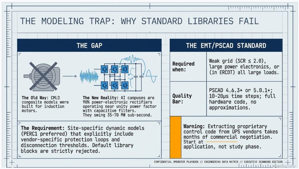
| Requirement | Typical requirement |
|---|---|
| Software | PSCAD/EMTDC 4.6.3+ (SPP, CAISO); ERCOT requires 5.0.1+; PJM requires 5.0.1+ |
| Compiler | Intel Fortran 12–15+, Visual Studio 2015+ |
| Time step | 10–20 μs |
| Inner control loops | Full detail, actual hardware code; approximations prohibited |
| Initialization | Self-initialize within 5 seconds |
| Protection | Balanced and unbalanced fault protection modeled |
| Benchmark tests | Fault ride-through at low SCR; V and P setpoint steps; overvoltage and undervoltage trip verification |
| Deliverables | .pscx, documentation, sample test case, plant SLD, supplier checklist, validation report |
| Submission deadline | SPP: 15 months before power injection |
Note: these criteria were written for inverter-based resources. ISOs are now applying the same bar to large power-electronic loads. Budget the time and the vendor cooperation accordingly — obtaining an accurate PSCAD model of a UPS from a manufacturer who considers the control code proprietary is a commercial negotiation, not an engineering task, and it takes months.
7.6 Harmonic and power quality study (IEEE 519), flicker (IEEE 1453)
Deliverable: harmonic load flow plus a frequency scan (impedance versus frequency at the POI) across the network configurations that matter — N-0, N-1, capacitor banks in and out, minimum and maximum short-circuit levels. Resonance almost always shows up in the minimum-fault-level case, which is the one people forget to run.
Published utility requirements worth designing to:
| Entity | Requirement |
|---|---|
| IEEE 519-2022 | Voltage and current distortion limits at the PCC, dependent on Isc/IL ratio |
| Dominion | IEEE 519 compliance; inter-harmonics limited to 25% of IEEE 519 values; instantaneous voltage fluctuation ≤3% at POI; permanent PQ monitoring with 290-day retention |
| Southern Company | Harmonic spectrum to the 50th order; permanent POI monitoring |
| PG&E | Total voltage THD ≤5%; phase balance ≤10% |
| FirstEnergy | IEEE 519; voltage unbalance ≤1.0% at point of service; motor-start dip ≤3% |
| Flicker (multiple TOs) | Pst ≤0.8, Plt ≤0.6 per IEEE 1453 |
dominated by switching-frequency and inter-harmonic content, which is exactly why the inter-harmonic clause exists. Get this from your UPS and PSU vendors, not from a textbook table.
Flicker matters little for steady IT load and a great deal for chiller motor starting and for AI training pulse loads in the 0.1–30 Hz band, which land squarely on the sensitive region of the flicker curve.
7.7 Ride-through and the load-loss problem
This is the single most consequential technical requirement in the guide, and it is a client-side design requirement, not just a study.
ERCOT NOGRR282 / NPRR1308 — Large Electronic Load ride-through (applies where ≥50% of site demand is power-electronic computational load):
| Voltage (per unit) | Must ride through for |
|---|---|
| >1.20 | May ride through or trip |
| 1.10–1.20 | 2.0 s |
| 0.90–1.10 | Continuous |
| 0.80–0.90 | 2.0 s |
| 0.50–0.80 | 0.5 s |
| 0.20–0.50 | 0.25 s |
| <0.20 | 0.15 s |
| Frequency | Must ride through for |
|---|---|
| >61.8 Hz | May ride through or trip |
| 61.2–61.8 Hz | 299 s |
| 58.8–61.2 Hz | Continuous |
| 57.0–58.8 Hz | 299 s |
| <57.0 Hz | May ride through or trip |
Plus, in ERCOT: continue consuming active power within 10% of pre-disturbance level during required ride-through; current must not exceed 125% of maximum normal operating current; sag-counting and instantaneous trip schemes are prohibited — filtered measurement with a window of at least one cycle is required; and settings must reflect actual equipment tolerances, not merely the minimum requirement. Initial compliance ran from November 14, 2025, with stricter 0.5–0.8 pu requirements from January 1, 2028. Non-compliance triggers a 90-day root-cause investigation, a 90-day remediation plan, and 180 days to implement. ERCOT may order immediate disconnection for imminent reliability risk.
SPP HILL fault ride-through covers similar ground with two distinctive requirements:
- Constant-current control is mandatory during disturbances; constant-power control is prohibited. This is easily missed and it matters enormously — constant-power control makes a voltage sag worse by drawing more current as voltage falls
- The load must tolerate six voltage fault-clearing attempts within 90 seconds and recover to ≥90% of pre-disturbance consumption within 1 second of voltage recovering to 0.9 pu
- Variable-speed drives may be exempted from the constant-current requirement and some duration requirements if the study demonstrates no adverse reliability effect
Only SPP and ERCOT publish explicit numeric POI-referenced curves. Everywhere else, the ride-through envelope is negotiated in the interconnection agreement. Our recommendation: propose the ERCOT or SPP curve as the reference standard in your own agreement, so you design once rather than retrofitting when your region catches up.
The design implications for your facility are severe and specific:
- Disturbance-counting logic — "transfer to backup after N dips in T seconds" — is the single biggest identified cause of the 1,500 MW Virginia event. It must be reviewed, and usually re-tuned or removed
- Diesel rotary UPS (DRUPS) produced extended disconnection requiring manual reconnection in the observed event — the worst of the three behaviors documented
- Static UPS, both centralized and rack-level distributed, recovered automatically — the best behavior
- Your equipment is designed to ITIC/CBEMA and SEMI F47 curves. Those are building electronics immunity curves, not grid ride-through curves. They do not match transmission requirements, and the mismatch is the root of the entire problem
The study deliverable your engineer should produce: a fault-scenario load-loss quantification. For a set of representative faults and reclose sequences on your POI lines, how many MW of the campus drops, for how long, and does the grid survive it. NERC recommends exactly this analysis. It also feeds directly into the reconnection ramp rate clause of your interconnection agreement.
7.8 Reactive power, power factor, capacitor and STATCOM sizing
- Utility power factor requirements at the POI vary: 0.97 lagging to 0.99 leading is a published example; others simply require operation "close to unity."
- Check both extremes, not just full load. A modern data center may sit leading at light load because of power-factor-correction and filter capacitance
- Deliverable: a reactive compensation study producing MVAr requirement versus load level, device selection (fixed capacitor bank, switched bank with steps, harmonic filter bank, SVC, or STATCOM), and confirmation that the device does not create resonance — tied back to the harmonic frequency scan
- STATCOM is increasingly the right answer for AI campuses, because the load swings sub-second and mechanically switched capacitors cannot follow. STATCOM also provides fast voltage support that helps ride-through
- Sizing inputs: the QV margin from the stability study, the flicker limit, and the MVAr band the TO requires
7.9 Arc flash, coordination, and inside-the-fence studies
These sit behind your POI but on the same critical path:
- Short circuit → coordination (TCC) → arc flash, in that order, per IEEE 1584-2018 (empirical model, electrode configuration VCB/VCBB/HCB/VOA/HOA, enclosure size correction), with results labeled per NFPA 70E
- Incident energy at every medium- and low-voltage work location, PPE category, arc flash boundary, printed labels
- Selective coordination, including DC coordination for the UPS battery system
- Load flow and voltage drop for the internal 34.5 kV → 13.8 kV → 480 V → rack path
- Tools: ETAP, SKM PowerTools, EasyPower, PowerFactory
7.10 Facility study, cost estimate, network upgrades, cost allocation
- Facility study deliverable: scope, single-line, general arrangement, schedule, and an AACE Class 3 or Class 2 cost estimate for the TO-side interconnection facilities and network upgrades, with a schedule showing long-lead equipment
- Split into Interconnection Facilities (customer-funded, directly assigned) versus Network Upgrades (cost allocation varies by region — and FERC's 2026 show-cause orders push hard toward 100% large-load funding with no socialization). PJM's Expedited Interconnection Track already imposes 100% network upgrade cost with no cost-sharing
- Include a contingent facilities list and a restudy trigger table
7.11 Curtailment, load flexibility, and loss-of-load studies
New in 2026, and increasingly the fastest path to energization:
- Curtailment analysis — how many hours per year, how many MW, under what triggers. PJM's Connect and Manage framework curtails large load before emergency demand response is activated. ERCOT's Provisional Controllable Load Resource pathway trades curtailability for capacity above your firm allocation. SPP's CHILL does the same
- FERC's rulemaking contemplates 60-day studies for loads willing to curtail — the single largest schedule lever available to a developer
- Flexible load capability study deliverable: MW curtailable, response time, duration, notification lead time, recovery ramp, number of events per year, and — critically — the control path (SCADA setpoint, DR aggregator, on-site generation or BESS dispatch). It must be technically demonstrable. Grid operators are getting skeptical of paper flexibility
- Ramp rate limits are becoming binding. Published and proposed figures cluster around 20 MW/minute. Design your workload orchestration and your on-site storage to meet whatever number your region lands on
PART 8 — SOFTWARE AND MODEL SUBMISSION
8.1 The toolset, and who uses what
| Tool | Vendor | Primary use | Where it matters |
|---|---|---|---|
| PSS®E | Siemens | Positive-sequence power flow, dynamics, short circuit | The U.S. default. Required by PJM, ERCOT, MISO, SPP, NYISO, ISO-NE |
| PSLF (Positive Sequence Load Flow) | GE Vernova | Power flow and dynamics | The WECC / Western ecosystem |
| PowerWorld Simulator | PowerWorld | Power flow, contingency, PV/QV, visualization | Consultants and TOs; unmatched for communicating results to non-engineers |
| TARA | PowerGEM | N-1 / N-1-1 contingency, transfer limits, PV/QV, deliverability, cascading | Licensed and used by essentially every RTO/ISO; if you are replicating an ISO's reliability study, this is usually the tool that produced it |
| PSCAD/EMTDC | Manitoba Hydro International | Electromagnetic transient simulation | The EMT standard. SPP and CAISO 4.6.3+; ERCOT and PJM 5.0.1+ |
| EMTP-RV | EMTP Alliance | EMT | Strong for insulation coordination and large-network EMT; accepted case by case. PSCAD is the safer default for ISO submissions |
| RTDS | RTDS Technologies | Real-time hardware-in-the-loop EMT | Controller HIL testing of UPS, BESS and STATCOM controls; accepted by some utilities at 500 kV |
| TSAT / DSA Tools | Powertech Labs | Transient and voltage security assessment | ERCOT requires TSAT for any PSS®E user-defined model |
| ASPEN OneLiner / DistriView | ASPEN | Short circuit and relay coordination | The dominant U.S. protection engineering tool. ISO-NE requires .OLR short-circuit files |
| CAPE | Siemens | Short circuit, coordination, relay setting automation | Used by large TOs maintaining a master relay database |
| ETAP | ETAP / Schneider | Industrial: load flow, short circuit, coordination, arc flash, harmonics, grounding, cable ampacity | The behind-the-fence workhorse for the data center itself |
| SKM PowerTools | SKM Systems | Same industrial suite; very common for arc flash and coordination | Often what your MEP engineer already uses |
| EasyPower | Bentley | Short circuit, coordination, arc flash, IEEE 80 grounding | Fast for arc flash label production |
| DIgSILENT PowerFactory | DIgSILENT | Power flow, RMS and EMT dynamics, harmonics, protection, QV | Common with international EPCs; less often required by U.S. ISOs |
| CYME / Synergi Electric | Eaton / DNV | Distribution analysis | Relevant if your campus feeds from distribution |
| WinIGS / CDEGS | AGI / SES | IEEE 80 grounding, GPR, transferred potential, layered soil, EM | Use CDEGS or WinIGS for shared building/switchyard grids |
| MATLAB/Simulink | MathWorks | Custom control models, prototype user-defined models, data fitting | Where a custom data-center load model is developed before porting to PSS/E UDM or PSCAD |
| PLS-CADD / PLS-POLE / TOWER | Power Line Systems | Transmission line design | Mandatory for the line deliverable |
8.2 Model submission requirements by region
| Region | Power Flow | Dynamics | Short circuit | EMT | Notes |
|---|---|---|---|---|---|
| PJM | PSS®E — 35.3.2 for current options (33.7.0 / 33.12.1 / 34.7 for older queues); .sav, .raw, .dyr | .dyr; user-defined models require source code, .dll and documentation | — | PSCAD 26.0.1, Intel Fortran 15+, VS2015+; 18 standardized test cases; PSCAD-to-PSS/E benchmark report | Station service load modeled with ID “XS”, auxiliary with “XA”. EMT guidelines currently address IBRs, not large loads |
| ERCOT | PSS®E v36 / v36C-compatible dynamic models were due June 1, 2026 | PSS®E; TSAT required if a user-defined model is submitted | — | PSCAD required for ALL Large Loads (PGRR144); hardware-benchmark standard, generic library blocks not acceptable | Model Quality Tests (fast start, large voltage disturbance) required for all Large Loads across PSS/E, PSCAD and TSAT. Converter Model Validation required for Large Electronic Loads |
| SPP | PSS/E including ACCC; PSS/MUST; IDV files for HILL | MDWG dynamic models; load model in CMLD and/or PERL — PERL preferred | Per NERC TPL-001-5.1 | PSCAD 4.6.3+, submission 15 months before injection | 10-year load forecast (summer, winter, light load) required at application |
| MISO | Per the MISO Planning Modeling Manual (MOD-032 requirements) | Under development for large loads | — | PSCAD required before GIA execution in ERAG/DPP | Proposed: ICCP telemetry plus PMU; 168-hour hourly and 6-hour 5-minute forecasts |
| NYISO | PSS®E; .sav / .raw, .dyr, .sld | PSS®E .dyr; user models add .dll plus source | ASPEN OneLiner .olr | Case by case | Model GSU and PSU transformers explicitly. NYISO bus-naming convention; reserved bus number blocks. Verify current version numbers with NYISO |
| ISO-NE | PSS/E .raw | PSS/E .dyr | ASPEN OneLiner .OLR | PSCAD “PSDX” with auxiliary files in a single ZIP | ISO-NE does not publish fixed version numbers — “compatible with the in-effect software version designated by ISO.” Contact info@iso-ne.com |
| CAISO / WECC | PSLF, PSS/E and PowerWorld all supported in WECC base cases | Per the WECC Data Preparation Manual | — | PSCAD/EMTDC 4.6.3+, 10–20 μs step | Motors ≥10 MVA modeled explicitly at manufacturer station service; ≥1 MW modeled separately; climate zone assignment required for every load |
| Non-ISO | Per each Planning Coordinator’s MOD-032 data requirements | Same | Same | Emerging | MOD-032 is the hook. Every Planning Coordinator publishes its own data requirements and reporting procedures — that is the document you must actually satisfy |
The one rule that saves projects: model version requirements change annually, sometimes mid-cycle. Check the specific ISO's model submission page at the start of every study cycle. A model submitted in the wrong PSS/E version is a rejected submission, and a rejected submission in a batch process can cost you six months or an entire cycle.
8.3 A note on model rejection
The most common reasons model packages get returned:
- Wrong software version
- Generic library blocks used where hardware-specific models are required
- User-defined model submitted without source code, DLL, or documentation
- PSS/E and PSCAD models that do not match each other in behavior
- Missing flat-start stability — the model does not initialize cleanly
- Load model that does not include protection and control behavior (no disconnection thresholds, no reconnection logic)
- Default parameters instead of as-built values, with no attestation
- Missing test cases or benchmark report
Every one of these is avoidable. In our experience, first-round model acceptance is the highest-leverage schedule improvement available on an interconnection project — a rejected package typically costs 30 to 90 days per round trip.
PART 9 — WHAT YOU MUST GIVE YOUR ENGINEERING FIRM
This is the checklist. Items marked ★ are the ones that most often stall projects.
9.1 Load characterization
- ★ MW ramp schedule by phase, expressed in MW by month, not year, for Phase 1 / 2 / 3 through ultimate build. ERCOT calls this the Load Commissioning Plan and non-performance against it can cancel your project
- Peak MW, average MW, and minimum MW at each phase; annual load factor
- ★ IT load versus non-IT (cooling and mechanical) split, as a percentage, at multiple load levels — a NERC Level 3 Alert requirement
- Power factor at the POI across the loading range, with the measurement point stated — including the light-load leading power factor case
- ★ Harmonic current spectrum of the IT load, magnitude and phase by order, to the 50th, plus inter-harmonic content, from your UPS and PSU vendors
- Ramp rates — maximum ramp up and down in MW/min and MW/s, for startup, shutdown and normal operation, plus sub-second and sub-synchronous cyclic content
- Expected sub-hourly demand profile and workload type (AI training, inference, colocation, crypto)
- Forecast capability — can you provide 5-minute to 7-day-ahead forecasts? Hourly forecasts on a rolling horizon? This is becoming a tariff obligation
9.2 Electrical architecture
- ★ Internal single-line diagram — POI → MV switchgear → transformers → UPS → PDU → rack
- Transformer sizes and impedances — MVA ratings (ONAN/ONAF), %Z on a stated base, winding configuration, tap ranges
- ★ UPS topology — double-conversion static, line-interactive, diesel rotary (DRUPS), or no UPS on the IT load (checkpoint-based, common on AI training). DRUPS is a flag: it produced the worst observed behavior in the 2024 event
- ★ Full protection and control settings of everything downstream of the POI — undervoltage and overvoltage pickup and time delay, underfrequency and overfrequency, rate-of-change-of-frequency, transfer-to-backup logic, and any disturbance-counting logic
- ★ Reconnection thresholds and reconnection ramp — levels, durations, and whether reconnection is automatic or manual
- Ride-through capability curve as designed (ITIC/CBEMA/SEMI F47), mapped against your region's required envelope, with an honest gap analysis
- Motor loads — chiller, pump and CRAH ratings, starting method (across-the-line, soft start, VFD), inrush, starting kVA, and whether they restart automatically after a dip
- Backup generation — diesel or gas turbine, MW, count, N+1 or 2N, start time, and emissions permit hour limits (this constrains demand response participation and is regularly overlooked)
- On-site generation and BESS — MW/MWh, inverter make and model, grid-forming versus grid-following, control mode, and whether it can export (and whether export is contractually prohibited)
- Reactive devices — capacitor banks (size, kV, steps), harmonic filters, STATCOM
- DC system — battery type, sizing, charger
- Redundancy tier — Uptime Institute Tier III (concurrently maintainable) or Tier IV (fault tolerant); N+1, 2N, 2N+1
9.3 The interconnection ask
- ★ Desired POI voltage (69 / 115 / 138 / 230 / 345 / 500 kV) and preferred bus configuration
- Preferred POI substation or line, with ranked alternatives
- ★ In-service date — and the "first power" date versus the "full load" date. These are different, both matter, and confusing them is a classic source of schedule dispute
- Firm versus non-firm service, and your willingness to accept curtailment. This is the fastest schedule lever available anywhere in the country right now
- Flexibility offer — MW curtailable, response time, duration, events per year, and the control path
- Remote disconnect acceptance
- Metering ownership preference — customer-owned versus utility-owned
9.4 Site and land
- ★ Site control evidence — deed, purchase agreement, or option. Some processes require site control locked for three years at application
- Legal description, acreage, parcel IDs
- ★ POI latitude/longitude to survey accuracy, plus final yard elevation at the termination structure, conductor and shield wire attachment elevations, and structure orientation where the TO requires it
- ★ ALTA/NSPS survey with easements and encumbrances
- ★ Geotechnical report — borings, bearing capacity, groundwater, and critically soil resistivity by Wenner four-pin method, multiple traverses, for the IEEE 80 study. Ask for resistivity explicitly. Standard geotechnical scopes omit it, and discovering that later costs a full remobilization
- Topographic survey, existing utilities, wetlands delineation, FEMA flood panel, Phase I environmental site assessment
- Environmental and permitting status — state siting authority, threatened and endangered species, cultural resources, air permit for gensets, stormwater
9.5 Commercial readiness
- ★ Study deposit and milestone payment readiness. Deposits now run from $100,000 to $500,000+ per stage, plus per-MW readiness deposits and per-MW security
- Evidence of financial commitment — grid operators now require quantified evidence of developer funding for load forecast inclusion
- ★ Disclosure of duplicative requests. Both PJM and Texas SB6 require you to disclose parallel requests for the same nameplate. Failure to disclose gets you removed from the forecast — or, in Texas, potentially denied
- State and local support — some fast-track processes require documented commitment from the siting authority to expedite permitting
- Executed offtake, lease, or construction commitments with financial penalties
- Corporate creditworthiness documentation
PART 10 — TIMELINE AND COST
10.1 Regional process timelines
| Region | Threshold | Study process and timeline |
|---|---|---|
| SPP | ≥10 MW at ≤69 kV; ≥50 MW above | HDPS 90 calendar days (SPP) in parallel with the TO's Load Connection Study. Supplemental EMT stage outside the 90-day window. HILLGA generation: ~7–8 months end to end |
| ERCOT | ≥75 MW | Batch process. Batch Zero interconnection study results were scheduled for April 2027; Batch 1 applications were slated for Summer 2027 on a ~6-month cadence. Currently disrupted by the August 2026 audit directive |
| NYISO | >10 MW at ≥115 kV; ≥80 MW below | SIS ~9 months ($150,000 deposit), then CTO facilities study 9–15 months ($200k–$500k), then 2+ years construction |
| PJM | ≥50 MW | TO/EDC process plus PJM load forecast. EIT for paired generation: ~180 days of study, GIA within 10 months |
| MISO (proposed) | >50 MW | Framework in development. ZGIA ~90 days. ERAS (generation) 3 months. Transmission builds: 7–10 years |
| ISO-NE | No tariff definition | PPS-3 Level II ~1–4 months; Level III ~3–12 months, inside a TO-led process |
| CAISO | Via PTO: Rule 30 covers 50–230 kV | Load flows through the CEC forecast → CPUC IRP → CAISO annual Transmission Planning Process |
| Non-ISO | Varies | BPA draft LLI v4 contemplates 180-day System Impact and 180-day Feasibility Studies plus a Facilities Study; participating utilities have characterized the total as approaching three years |
| FERC target | ≥50 MW above 69 kV | 60–90 day tailored studies — where all six RTOs are being pushed |
Real-world totals, from practice: roughly 12 months in an uncongested territory with existing headroom; 3 to 5 years in constrained markets; and reports of 7 years in the most congested corridors. Engineering deliverables are almost never the critical path. Transformer and breaker lead times and the grid operator's study queue are.
10.2 Engineering deliverable durations
Typical for a 2–4 position 230 kV POI station (industry practice; varies by TO and contract):
| Phase | Duration |
|---|---|
| Conceptual, siting, POI screening | 4–8 weeks |
| Interconnection application data package and models | 4–8 weeks |
| 30% design | 8–12 weeks |
| 60% design | 12–16 weeks |
| 90% design | 8–12 weeks |
| Issued for construction | 4–6 weeks |
| Total engineering | ~10–14 months, overlapping the study process |
| Long-lead procurement (issued at 60%) | 26–52+ weeks after PO, longer for large HV transformers |
| Construction and commissioning | 12–24 months |
Studies run in parallel: grounding and lightning land at 60%; arc flash and coordination at 90%; EMT and dynamic model development typically start at the interconnection application and iterate for 6 to 18 months. That last item is the one developers consistently underestimate.
10.3 Cost benchmarks
Transmission and substation unit costs (from MISO's published Transmission Cost Estimation Guide, which is the best public source; includes contingency and AFUDC):
| Item | Cost |
|---|---|
| 138 kV line, single circuit | $2.0–2.3M per mile |
| 230 kV line, single circuit | $2.1–2.6M per mile |
| 345 kV line, single circuit | $3.4–4.1M per mile |
| 500 kV line, single circuit | $4.3–5.1M per mile |
| 230 kV double circuit | $3.5–4.0M per mile |
| 345 kV double circuit | $5.8–6.4M per mile |
| Add one ring-bus position, 138 kV | $1.7M |
| Add one ring-bus position, 230 kV | $2.2M |
| Add one ring-bus position, 345 kV | $3.4M |
| Add one ring-bus position, 500 kV | $5.3M |
| New 4-position ring bus, 138 kV | $8.9–13.4M |
| New 4-position ring bus, 230 kV | $12.6–18.0M |
| New 4-position ring bus, 345 kV | $19.3–27.0M |
| Power transformer | $5,050–$18,475 per MVA depending on winding combination |
Interconnection cost per kW (from national laboratory analysis; generator-side but directionally useful): completed projects around $194/kW, active around $294/kW, withdrawn around $671/kW. Small projects (1–50 MW) around $763/kW; very large (750+ MW) around $244/kW. At $500/kW, a 100 MW project is roughly $50 million.
Order-of-magnitude data center interconnection totals (practitioner ranges, not published rates):
- Core substation equipment: $3–7M
- Full utility interconnection including lines and easements: $20M–$100M+
- Power-constrained regions: $40–60M+
- On-site backup generation: $3–10M+ per MW
Engineering fees: planning-grade estimates typically apply project management, A&G, and engineering adders totaling 8–10% of project cost. A real EPC or owner's-engineer fee on a data center POI runs higher — commonly 6–12% of installed cost for full design plus
owner's engineer scope. Industry practice, not a published rate.
Study deposits: ISO study deposits currently run $50,000 to $640,000 per stage depending on size and region, plus per-MW readiness deposits ($4,000–$20,000/MW range in published processes) and per-MW financial security in some jurisdictions.
PART 11 — STANDARDS REFERENCE
11.1 IEEE — substation and physical design
| Standard | Subject | Where it lands in your project |
|---|---|---|
| IEEE 80 | Safety in AC substation grounding | Grounding grid study, step and touch voltage |
| IEEE 81 | Measuring earth resistivity, ground impedance and earth surface potentials | Soil resistivity data collection and grounding verification testing |
| IEEE 998 | Direct lightning stroke shielding of substations | Shielding study, mast and shield wire layout |
| IEEE 605 | Rigid bus design | Bus ampacity, short-circuit forces, insulator cantilever |
| IEEE 1427 | Electrical clearances | General arrangement and section drawings |
| IEEE 485 / 1184 | Battery sizing — VLA/VRLA and lithium-ion | DC system design |
| IEEE 2778 | Solar power plant grounding | If on-site PV is present |
11.2 IEEE — power quality and performance
| Standard | Subject | Where it lands |
|---|---|---|
| IEEE 519 | Harmonic control at the point of common coupling | Harmonic study; universally referenced by TOs |
| IEEE 1453 | Flicker (Pst, Plt) | Flicker study; Pst ≤0.8 and Plt ≤0.6 are typical utility limits |
| IEEE 1584 | Arc flash hazard calculation | Arc flash study and labels |
| IEEE 2800 | Interconnection of inverter-based resources to transmission | Applies to your on-site BESS, PV and grid-forming assets. It does not apply to loads — but its ride-through envelope structure is the template being borrowed for load requirements |
| IEEE 2800.2 (published June 2026) | Test and verification procedures for IBRs | Conformity assessment architecture; again IBR-specific but precedential |
| IEEE 1547 | DER interconnection at distribution | If any DER sits below the POI on distribution |
11.3 IEEE — apparatus (C37.x and C57.x)
| Standard | Subject |
|---|---|
| IEEE C37.2 | Device function numbers — all P&C drawings |
| IEEE C37.04 / C37.06 / C37.010 | HV circuit breaker rating structure, preferred ratings, application — the breaker duty study |
| IEEE C37.09 | Breaker test procedures — factory and field acceptance |
| IEEE C37.011 | Transient recovery voltage — breaker application, EMT switching study |
| IEEE C37.90 / .91 / .102 / .230 | Relay standards, transformer protection, generator protection, substation IED |
| IEEE C37.118 / IEC 61850-90-5 | Synchrophasors — PMU deliverables |
| IEEE C37.238 / IEC 61850 | Substation automation and precision timing |
| IEEE C57.12.00 / .12.90 | Power transformer general requirements and test code |
| IEEE C57.13 / C57.13.6 | Instrument transformers; 115 kV and above — CT/PT accuracy classes for revenue metering |
| IEEE C57.91 | Loading mineral-oil transformers — overload capability and ONAN/ONAF ratings for phased load |
| IEEE C57.109 / C57.12.59 | Through-fault duration; dry-type short circuit — transformer damage curves for coordination |
| IEEE C62.11 / C62.22 | Surge arresters and arrester application — insulation coordination |
11.4 NERC Reliability Standards
| Standard | Why it matters to you |
|---|---|
| FAC-001 | Facility interconnection requirements. The transmission owner must publish these, and the published document is the definitive list of what you must submit. Read your TO's FAC-001 document before you do anything else |
| FAC-002 | Coordination of new facilities studies — obligates the TO/TP/PC to study your interconnection |
| MOD-032 | Data for power system modeling and analysis — the model submission obligation and format. Each Planning Coordinator publishes its own requirements under this standard |
| MOD-033 | Steady-state and dynamic system model validation |
| MOD-026 / MOD-027 | Generator excitation and turbine/governor model verification — applies to your on-site generation |
| TPL-001 | Transmission system planning performance, P0 through P7 contingency categories. Loss of your large load is now being treated as a credible contingency |
| PRC-002 | Disturbance monitoring and reporting — DFR, SER, DDR |
| PRC-005 | Protection system maintenance |
| PRC-024 | Generator frequency and voltage protective relay settings — the template for the load-side ride-through envelopes now being written |
| PRC-026 | Relay performance during stable power swings |
| PRC-028 | Disturbance monitoring for IBRs — cited in NERC's large-load guideline for PMU specifications |
| BAL / IRO / COM families | Balancing, reliability coordination and communications — the standards families under review in NERC Project 2026-02 |
Two current NERC items you must track:
- The Level 3 "Essential Action" Alert on computational loads (May 2026), applicable to loads ≥20 MW connected at 60 kV containing more than 1 MW of IT load. Its seven actions — modeling data requirements, system studies, qualified-change definitions, commissioning process, protection coordination, dynamic fault recording, and operational communication — are already flowing into what your TO asks of you
- NERC Project 2026-02, "Reliability Standards to Address Computational Load — Phase I." New glossary definitions for "Computational Load" and "Computational Load Entity," Rules of Procedure changes creating a registered entity category, and a consolidated standard. Board adoption targeted December 2026, aligned to FERC's December 31, 2026 filing deadline. If this lands as drafted, data centers become NERC-registered entities for the first time — with direct compliance obligations, audits and potential penalties.
11.5 Other standards
| Standard | Subject |
|---|---|
| NESC (ANSI C2) | Clearances, grades of construction, loading districts |
| ANSI C84.1 | Preferred voltage ratings, Range A and B — steady-state voltage criteria |
| ANSI C12.20 | Meter accuracy classes |
| NFPA 70 (NEC) | Building and site electrical |
| NFPA 70E | Electrical safety in the workplace — arc flash labels and PPE |
| NFPA 780 | Lightning protection for buildings — distinct from IEEE 998 |
| IEC 60909 | Short-circuit current calculation — if any equipment is IEC-rated |
| IEC 61850 | Substation communication and digital substation architecture |
| Uptime Institute Tier Standard | Tier I–IV redundancy definitions (a private standard, not IEEE or ANSI) |
| SEMI F47 / ITIC (CBEMA) | Equipment voltage sag immunity — what your IT equipment is actually designed to, and the source of the mismatch with grid ride-through requirements |
| CIGRE TB 909 | Sub-synchronous oscillation screening — referenced in SPP's supplemental EMT stage |
PART 12 — WHERE PROJECTS DIE
Twelve failure modes we see repeatedly. Every one is avoidable.
1. Picking the site before screening the POI. Land, water, fiber and tax abatement get evaluated; grid headroom does not. The site is bought, and then the interconnection study says the nearest available capacity is 40 miles and $80 million away. POI screening is the cheapest de-risking available and it must happen before land commitment.
2. Submitting an incomplete application. Deficiency cure periods are 10 to 15 days. In a batch process, missing one drops you to the next batch — six months to a year.
3. Wrong model version. A PSS/E case in the wrong version is a rejected submission. Check the version requirement at the start of every cycle, not from last year's notes.
4. Generic models where hardware-specific models are required. ERCOT explicitly states generic PSCAD library blocks are not acceptable for large loads. Getting a hardware-benchmarked UPS model out of a manufacturer takes months of commercial negotiation. Start that conversation at application, not at study.
5. Not disclosing duplicate requests. PJM removes undisclosed duplicates from the load forecast. Texas SB6 requires disclosure. The practice of shopping the same nameplate across five utilities to see who moves fastest is now being explicitly policed.
6. Ignoring the geotech scope. Standard geotechnical scopes do not include Wenner four-pin soil resistivity. Discovering that when the grounding study starts means a remobilization and a schedule hit for a line item that costs almost nothing if requested up front.
7. Treating ride-through as an IT problem. Your UPS vendor designed to ITIC and SEMI F47. Your grid operator requires a transmission ride-through envelope. These are different curves. The gap analysis has to happen at design, because retrofitting UPS control logic across a built campus is enormously expensive.
8. Leaving disturbance-counting logic in place. "Transfer to backup after three dips in 60 seconds" is what turned a normally-cleared fault into a 1,500 MW event. It is now a specific review item. Find it, and change it, before commissioning.
9. Sizing CTs for ultimate load only. Phase 1 at 20% of ultimate CT rating produces metering accuracy that will not survive a revenue audit.
10. Designing a ring bus you cannot expand. Four positions is the practical ring bus limit. If your campus roadmap goes to eight, lay out for a breaker-and-a-half conversion at 30% design.
11. Underestimating long-lead procurement. Design is not the critical path. Large HV transformers and HV breakers are. Specifications must be issued for procurement at 60% design.
12. Promising flexibility you cannot deliver. Grid operators are increasingly skeptical of paper curtailability. If you commit to 100 MW of curtailment in 10 minutes, you need a demonstrable control path — SCADA setpoint, workload orchestration, on-site generation or BESS — and you will be tested on it. Emissions permit hour limits on backup gensets frequently make the committed flexibility undeliverable in practice.
PART 13 — FREQUENTLY ASKED QUESTIONS
ABOUT KEENTEL ENGINEERING
Keentel Engineering is a power system and substation engineering firm serving utilities, IPPs, data center developers and industrial clients across the United States. We provide end-to-end POI interconnection support — from feasibility and site screening through dynamic modeling, protection design, and final energization.
Our POI Interconnection Services
Interconnection strategy and screening
- Multi-site POI feasibility screening and ranking
- Regional process and tariff analysis (PJM, MISO, SPP, ERCOT, CAISO/WECC, NYISO, ISO-NE, and non-ISO utilities)
- Interconnection application preparation and data package assembly
- Deficiency response and grid operator coordination
Power system studies
- Steady-state load flow: N-0, N-1, N-1-1 across seasons and ramp phases
- Short circuit, fault duty and breaker duty (ANSI and IEC)
- Transient stability, voltage stability, PV and QV analysis
- Dynamic load modeling — CMLD, PERC1 and user-defined models
- EMT / PSCAD studies: sub-synchronous oscillation, control interaction, insulation coordination, switching transients
- Harmonic and power quality analysis (IEEE 519), flicker (IEEE 1453)
- Ride-through assessment and fault-scenario load-loss quantification
- Reactive compensation and STATCOM/SVC sizing
- Arc flash (IEEE 1584), coordination, and grounding (IEEE 80)
Modeling and model submission
- PSS®E, PSCAD, ETAP, SKM PowerTools, DIgSILENT PowerFactory, CYME, EasyPower
- Model quality testing, cross-platform benchmarking, and validation reports
- MOD-032 data package preparation
- First-submission acceptance is our benchmark, not a stretch goal
Substation and transmission design
- Substation primary and secondary design, conceptual through IFC
- One-line, three-line, general arrangement, sections and elevations
- Protection and control design, relay settings, coordination and commissioning support
- Grounding grid and lightning protection design
- Revenue metering, SCADA, RTU and ICCP points development
- Transmission line design and routing
- IEC 61850 substation automation
Compliance and owner's engineering
- NERC O&P 693 compliance services
- NERC Level 3 Alert engineering support — modeling parameter response, study updates, commissioning procedures, fault recording, and protection coordination
- PRC-019, PRC-024, PRC-025 and PRC-027 documentation
- Owner's engineer services: specification, bid evaluation, design review, FAT/SAT witnessing, commissioning oversight
Adjacent capabilities
- Utility-scale solar, wind and BESS interconnection
- MEP engineering
- Nuclear power plant services
- Transmission and distribution engineering across ComEd, PJM and other territories
Regional track record
Keentel has delivered interconnection engineering across PJM (230 kV), ERCOT (345 kV), WECC (230 kV) and NYISO (138 kV) systems, including hybrid solar-plus-storage, wind, and BESS facilities. Representative outcomes include full first-submission acceptance of dynamic and short-circuit models, zero requests for information following initial package review, and sub-synchronous resonance risk assessment with EMT modeling on weak-grid interconnections.
Software depth
ETAP (15+ years) · PSS®E (14+ years) · SKM PowerTools (15+ years) · AutoCAD (27+ years) · CYME (27+ years) · SEL (27+ years) · Bentley MicroStation (14+ years) · EasyPower (10+ years) · DIgSILENT PowerFactory (8+ years) · PSCAD (5+ years)
Contact
Head Office — Tampa, FL 400 N Ashley Dr, Suite 2600, Tampa, FL 33602 · 813-389-7871
Austin, TX — 5900 Balcones Drive, Suite 100, Austin, TX 78731 · 512-591-0752 Sacramento, CA — 1401 21st St, Suite R, Sacramento, CA 95811 · 916-913-4524 Baltimore, MD — 306 W Redwood St, Suite 200, Baltimore, MD 21201 · 410-225-2181
Email: contact@keentelengineering.com Web: keentelengineering.com
Talk to us before you buy the land. POI screening across candidate sites is the cheapest risk reduction available in data center development, and the last point at which changing your answer is free. Schedule a consultation at keentelengineering.com.
SOURCES AND VERIFICATION NOTES
Primary sources
Federal and reliability
- FERC Docket RM26-4, Interconnection of Large Loads to the Interstate Transmission System — ferc.gov/rm26-4
- FERC Section 206 show-cause orders, June 18, 2026: PJM EL26-67, SPP EL26-68, NYISO EL26-69, MISO EL26-70, CAISO EL26-71, ISO-NE EL26-72
- FERC order on PJM co-located load, EL25-49 series
- FERC order directing NERC computational load standards, RD26-7, July 16, 2026
- FERC Order No. 2023 / 2023-A (generator interconnection reform); Order No. 1920 / 1920-A (transmission planning and cost allocation); Order No. 845 (surplus interconnection service)
- NERC, Incident Review: Simultaneous Voltage-Sensitive Load Loss, January 8, 2025
- NERC Level 3 "Essential Action" Alert on computational load, May 2026
- NERC Reliability Guideline, Risk Mitigation for Emerging Large Loads, 2026
- NERC white paper, Characteristics and Risks of Emerging Large Loads
- NERC Large Loads Action Plan and Project 2026-02 — nerc.com/initiatives/large-loads-action-plan
- WECC, An Assessment of Large Load Interconnection Risks in the Western Interconnection, February 2025
- WECC Data Preparation Manual and Base Case documentation — wecc.org
Grid operators
- PJM Manual 14H (New Service Requests Cycle Process), Manual 14B, 14C, 14G; PJM Dynamic Model Development Guidelines; PJM EMT Model Development Guidelines; PJM Board CIFP-LLA decision letters (January and July 2026); PJM OATT — pjm.com
- MISO Tariff Attachment X, Business Practice Manuals, Planning Modeling Manual, ERAS Informational Guide, Large Load Working Group materials, Transmission Cost Estimation Guide — misoenergy.org
- SPP HILL Integration materials, DISIS Manual, Consolidated Planning Process Manual, HILL Fault Ride-Through Requirements v1.0, EMT Model Requirements — spp.org
- ERCOT Planning Guide Sections 5, 6 and 9; NPRR1234/PGRR115; PGRR144; PGRR145/NPRR1325; NOGRR282/NPRR1308; Large Load Integration page and forms; DWG Procedure Manual — ercot.com
- CAISO Large Load Considerations Issue Paper (January 2026), Large Loads Technical Requirements Straw Proposal (June 2026), Large Loads Straw Proposal (August 2026), EMT Modeling Requirements, Appendix DD (GIDAP), CAISO Tariff — caiso.com
- NYISO OATT Attachment P, Attachment HH, Manual 23 (TEI Manual), Gold Book, Power Trends — nyiso.com
- ISO-NE Transmission Markets and Services Tariff §I.3.9, Planning Procedures PP5-0/5-1/5-3/5-6, Interconnection Request Technical Data Submittal Guidance, CELT Report — iso-ne.com
State and utility
- Texas SB6 (89th Legislature, 2025); PUCT Project 58481 / 16 TAC §25.194
- CPUC A.24-11-007 (PG&E Electric Rule 30), R.24-01-018 (energization / SB 410), R.26-04-009 (data center rate design)
- NY PSC Case 26-E-0045, Interconnection Reforms for Large Loads
- Transmission owner FAC-001 Facility Interconnection Requirements documents (Dominion Energy Virginia, FirstEnergy, BPA, and others)
- BPA Line and Load Interconnection procedure and Metering Application Guide
- EEI list of large customer projects and tariffs
Cost and analysis
- MISO Transmission Cost Estimation Guide (MTEP series)
- Lawrence Berkeley National Laboratory interconnection cost studies
Verification notes — read before publishing or relying on specific figures
This guide was compiled on August 20, 2026 from primary regulatory documents and reputable secondary analysis. The following items were identified as uncertain, in dispute between sources, or in active flux, and should be verified against the current primary source before you rely on them commercially:
- FERC show-cause responses filed August 17, 2026 in EL26-67 through EL26-72, and whether FERC granted the 90-day abeyance motions filed by several RTOs and transmission owner groups in early August 2026. Several regional processes will change materially depending on the outcome.
- ERCOT Batch Zero schedule following the August 3, 2026 gubernatorial audit directive and the suspension of the August 7, 2026 classification deadline. Confirm current dates with ERCOT and your TSP.
- PUCT 16 TAC §25.194 — adoption status and the per-MW security and fee figures. Published summaries conflict between $50,000/MW and $100,000/MW. Pull the rule text from PUCT Project 58481.
- PJM Expedited Interconnection Track readiness deposit — published sources report $10,000, $15,000 and $20,000 per MW in different documents. Verify against the accepted tariff sheets.
- MISO large load tariff filings made in late July 2026 (reliability requirements, telemetry/PMU, operational forecasting) — docket numbers and acceptance status.
- MISO ERAS sunset date — sources conflict between August 31, 2027 and December 31, 2028.
- MISO numerical ride-through envelopes for large loads — themes are published; specific values were not located in public documents.
- SPP HILL fault ride-through numerical values — verify against SPP's HILL Fault Ride Through Requirements v1.0 directly.
- ISO-NE currently in-effect PSS/E, PSCAD and ASPEN OneLiner version numbers — ISO-NE deliberately does not publish fixed versions. Contact irtt@iso-ne.com.
- NYISO software version numbers and the precise tariff location of load interconnection procedures. FERC's own finding in EL26-69 is that NYISO's load procedures are not described in the tariff with sufficient clarity — much of the process lives in manuals and practice.
- CAISO Large Loads Straw Proposal (August 11, 2026) contents and the resulting Draft Final Proposal — the most important open document for California.
- PG&E Electric Rule 30 final decision status.
- ERCOT queue totals — published figures range from 410 GW to 474 GW depending on source, date and accounting method. Cite the specific source and date each time.
- Third-party queue trackers are not official grid operator data. ERCOT's own Large Load Portal was not live as of mid-2026.
- Transmission owner rosters, cost benchmarks, acreage rules of thumb, stage-gate deliverable matrices, engineering fee percentages and total engineering durations are industry practice compiled from multiple sources, not published rules. They vary by transmission owner, region and contract.
Disclaimer. This guide is provided for general information and does not constitute legal, regulatory, or engineering advice for any specific project. Interconnection requirements are project-specific, region-specific, and changing rapidly. Nothing here creates an engineer-client relationship or a warranty of any kind. Verify all rules, thresholds, deadlines and figures against the current tariff, protocol, guide or rule before making commercial decisions. Keentel Engineering would be glad to help you do exactly that.

About the Author:
Sandip "Sonny" R. Patel, P.E.
IEEE Senior Member · Founder & CEO, Keentel Engineering
In 1995, Sonny Patel earned his Electrical Engineering degree from the University of Illinois. But degrees don't build legacies — action does.
For three decades, he has worked the power industry from every side of the table: 16 years as a utility engineer at Exelon/Commonwealth Edison; generation leadership across hydroelectric, industrial steam turbine, and a 9 GW renewable fleet; NERC Regional Entity Senior Compliance Engineer and Audit Team Lead, auditing some of the nation's largest utilities; and testing and commissioning lead on equipment up to 765 kV — the very top of the North American grid.Utility. Generator. Regulator. Consultant. Few engineers have seen all four seats. Fewer still have sat in them.
His experience spans nuclear, hydro, conventional generation, renewables, oil and gas, mining — and today's data centers, where he is authoring a three-book series on data center design. He is a Licensed Professional Engineer in six states and a Licensed Electrical Contractor in Florida (Unlimited EC) — he doesn't just design the work; he's qualified to stand behind its execution.Today, as Founder and CEO of Keentel Engineering, Sonny leads a nationwide team of engineers delivering substation design, power system studies, NERC compliance, and commissioning — done right, coast to coast.Three decades. Every side of the table. One standard: accountable engineering.
Services

Let's Discuss Your Project
Let's book a call to discuss your electrical engineering project that we can help you with.
About the Author:
Sandip "Sonny" R. Patel, P.E.
IEEE Senior Member · Founder & CEO, Keentel Engineering
In 1995, Sonny Patel earned his Electrical Engineering degree from the University of Illinois. But degrees don't build legacies — action does.
For three decades, he has worked the power industry from every side of the table: 16 years as a utility engineer at Exelon/Commonwealth Edison; generation leadership across hydroelectric, industrial steam turbine, and a 9 GW renewable fleet; NERC Regional Entity Senior Compliance Engineer and Audit Team Lead, auditing some of the nation's largest utilities; and testing and commissioning lead on equipment up to 765 kV — the very top of the North American grid.
Utility. Generator. Regulator. Consultant. Few engineers have seen all four seats. Fewer still have sat in them.
His experience spans nuclear, hydro, conventional generation, renewables, oil and gas, mining — and today's data centers, where he is authoring a three-book series on data center design. He is a Licensed Professional Engineer in six states and a Licensed Electrical Contractor in Florida (Unlimited EC) — he doesn't just design the work; he's qualified to stand behind its execution.
Today, as Founder and CEO of Keentel Engineering, Sonny leads a nationwide team of engineers delivering substation design, power system studies, NERC compliance, and commissioning — done right, coast to coast.Three decades. Every side of the table. One standard: accountable engineering.
Leave a Comment
Thank you for contacting us.
We will get back to you as soon as possible.
We will get back to you as soon as possible.
Oops, there was an error sending your message.
Please try again later.
Please try again later.
Related Posts

By SANDIP R PATEL
•
October 3, 2026
Engineering guide to PRC-028 disturbance recording, PRC-029 ride-through and PRC-030 event detection for inverter-based resources.

By SANDIP R PATEL
•
October 3, 2026
A practical guide to SSO classification, SSR, PEDI, Wind-SSCI, EMT analysis, mitigation and protection based on CIGRE TB 909.

By SANDIP R PATEL
•
October 6, 2026
Learn ERCOT generator testing for PFR, MOD-025 and MOD-026/027, including staged tests, capability verification, dynamic models and field testing.

By SANDIP R PATEL
•
October 3, 2026
Learn how PV string I-V curve testing identifies hidden solar performance losses, including soiling, shading, mismatch, degradation, and wiring faults.

By SANDIP R PATEL
•
October 3, 2026
Learn how active harmonic filters work, how to size AHF systems, reduce VFD harmonics, calculate losses, and meet IEEE 519 TDD limits at the PCC.
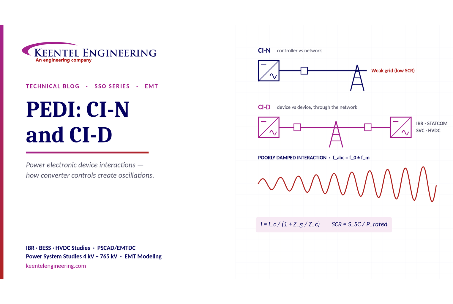
By SANDIP R PATEL
•
October 3, 2026
Learn power electronic device interactions (PEDI), including CI-N and CI-D, weak-grid stability, SCR, EMT studies, impedance analysis and mitigation for IBRs.
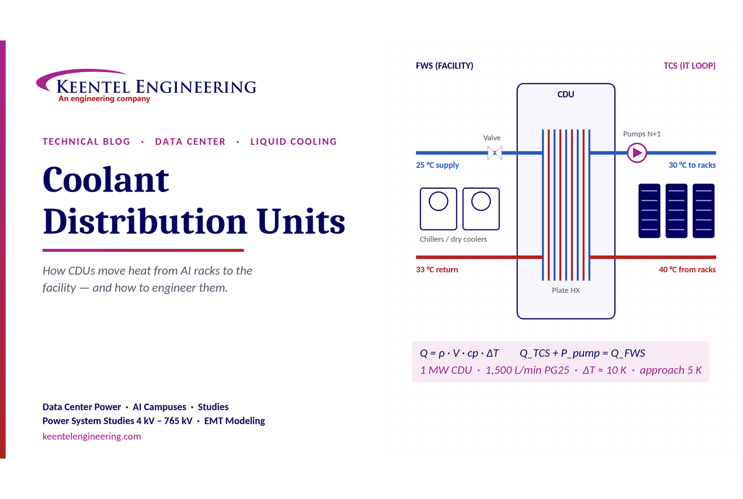
By SANDIP R PATEL
•
October 3, 2026
Learn how data center coolant distribution units (CDUs) work, including FWS and TCS loops, heat transfer, sizing, redundancy and liquid cooling for AI data centers.
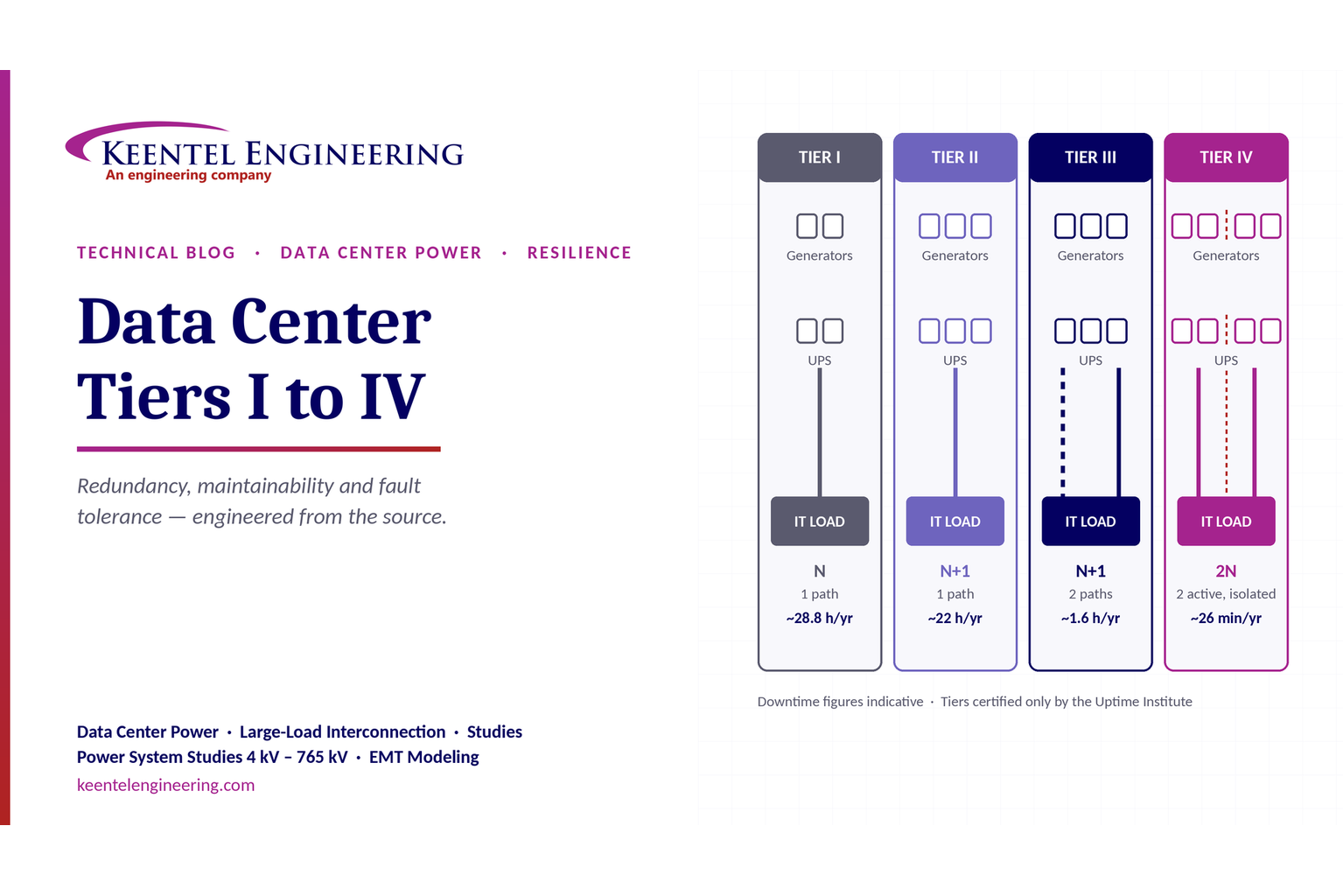
By SANDIP R PATEL
•
October 3, 2026
Compare Data Center Tiers I–IV, including redundancy, uptime, Tier III concurrent maintainability, Tier IV fault tolerance, UPS, generators and power design.

By SANDIP R PATEL
•
October 3, 2026
Learn how BESS supports grid stability through fast frequency response, voltage support, oscillation damping, black start, grid-forming controls and EMT studies.





