A Coordinated Electric System Interconnection Review—the utility’s deep-dive on technical and cost impacts of your project.
Challenge: Frequent false tripping using conventional electromechanical relays
Solution: SEL-487E integration with multi-terminal differential protection and dynamic inrush restraint
Result: 90% reduction in false trips, saving over $250,000 in downtime
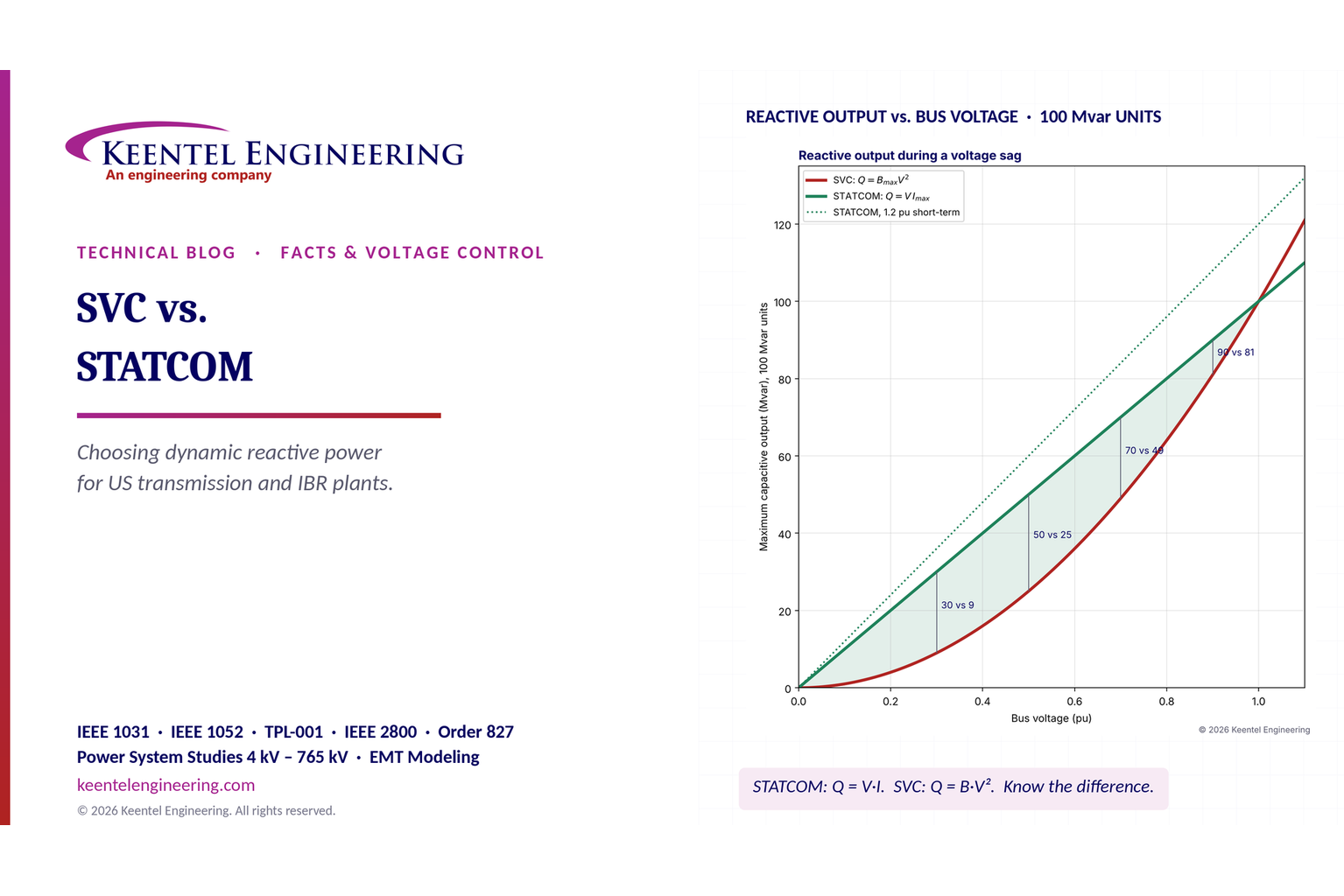
The three operating regions you have to design to
| Device | Output vs voltage | Response | Best suited to | Main limitations |
|---|---|---|---|---|
| Mechanically switched capacitor or reactor | Proportional to voltage squared | Seconds; discrete steps; limited switching operations per day | Steady-state reactive supply, voltage profile, loss reduction | No dynamic capability; step voltage change on switching; capability collapses when most needed |
| Static var compensator | Capacitive branches proportional to voltage squared | A few cycles; continuously controllable | Continuous control where cost matters and deep voltage support is not the driver | Square-law capability loss; harmonic filters are part of the plant and interact with the network |
| STATCOM | Approximately proportional to voltage — constant current capability | One to two cycles closed loop; converter response faster still | Voltage stability margin, weak interconnections, fast disturbance recovery, flicker and unbalance compensation | Higher capital cost; converter losses; adds a converter and its control dynamics to the network |
| Synchronous condenser | Governed by machine capability and excitation | Excitation response in the hundreds of milliseconds; inherent inertial response instantaneous | System strength and inertia, short-circuit contribution, black start support | Rotating plant with maintenance and losses; slower controlled response than a converter |
| STATCOM with energy storage | Reactive as a STATCOM, plus real power within the storage rating | As STATCOM for reactive; real power limited by storage | Where a real power deficiency is part of the problem | Cost and complexity of the storage; different failure and maintenance profile |
| Service area | What we do for SST campuses | Typical deliverables |
|---|---|---|
| Grid interconnection | Site screening, large-load applications, independent studies, utility and RTO coordination in ERCOT, NYISO, PJM and other markets | Screening reports, application data packages, load flow, contingency and stability studies, study review memos |
| EMT modeling | Model requirements, vendor model review, campus aggregation, ride-through, weak-grid, control interaction and load-oscillation studies | EMT model specifications, model acceptance reports, PSCAD study reports, SCR screening |
| MV/MVDC system studies | AC and DC short-circuit, DC protection philosophy, AC protection, arc flash, grounding, insulation coordination | Study reports, protection philosophy documents, settings files, arc flash labels, interface control documents |
| Power quality | Emission requirements, frequency scans, IEEE 519-2022 compliance, filter sizing, flicker assessment | Harmonic study reports, filter specifications, monitoring plans |
| Substation and transmission design | HV/EHV substations, MV collectors, transmission lines, utility interface protection | Physical and electrical drawing packages, specifications, bills of material, protection and control design |
| NERC compliance | Registration and applicability, ride-through requirements, model validation, monitoring, compliance programs | Applicability assessments, compliance programs, evidence packages, model validation reports |
| Owner's engineer and QA/QC | SST, storage and substation specifications, design reviews, FAT and SAT plans and witnessing, multi-unit QA | Specifications, review comments, test plans, witness reports, due diligence reports |
| Onsite generation and BESS | Role definition and sizing, DC bus control architecture, fire and code compliance coordination, performance testing | Sizing studies, control architecture documents, specifications, test procedures |
Storage and generation
| Term | Meaning |
|---|---|
| AFE | Active front end. The actively switched AC/DC stage of an SST that connects to the MV grid and sets its grid behavior. |
| Aggregated model | A model in which many converters are represented by a smaller number of equivalent converters to make campus-scale simulation practical. |
| Arc flash | The release of energy from an electric arc fault, assessed as incident energy at a working distance to set PPE and safe work practices. |
| BESS | Battery energy storage system. |
| Blocking | Turning off all converter switches so the converter stops feeding current, used to limit DC faults. |
| Composite load model | A positive-sequence load model that combines several load types, such as motors, electronics and static loads. |
| DAB | Dual active bridge. An isolated DC/DC converter topology with active bridges on both sides of a high-frequency transformer. |
| DC-link | The internal DC capacitor bank between converter stages. |
| EMT | Electromagnetic transient simulation. Time-domain simulation with microsecond time steps, used to study fast converter and network behavior. |
| FAT | Factory acceptance test. |
| Grid-forming | A converter control mode that sets its own voltage and frequency reference rather than following the grid's, providing support to weak grids. |
| HIL | Hardware-in-the-loop testing, in which a real controller is tested against a real-time simulation. |
| IBR | Inverter-based resource. Generation or storage connected to the grid through power electronics. |
| Insulation coordination | Matching the insulation strength of equipment to the voltage stresses the system produces, with surge protection where needed. |
| ISC/IL | The ratio of available short-circuit current to maximum demand load current at the point of common coupling, used to set IEEE 519 limits. |
| ISOP | Input-series, output-parallel. A modular converter arrangement that shares a high input voltage across cells in series and combines their outputs in parallel. |
| Large load | A load large enough to affect transmission system reliability. Definitions vary, for example 75 MW and above under Texas SB 6, or loads above 20 MW in the federal rulemaking proposal. |
| LVDC | Low-voltage DC, such as 800 VDC or ±400 VDC rack distribution. |
| MFT | Medium-frequency transformer. The compact isolation transformer inside an SST, operating at kilohertz frequencies. |
| MMC | Modular multilevel converter. A converter built from many submodules with their own capacitors, producing a stepped multilevel waveform. |
| MVDC | Medium-voltage DC distribution, roughly 1 kV to 35 kV DC in common usage. |
| OE | Owner's engineer. An independent engineer representing the owner's technical interests. |
| PCC / POI | Point of common coupling / point of interconnection, where the campus connects to the utility system and where compliance is usually assessed. |
| PLL | Phase-locked loop. The control element that tracks grid voltage phase and frequency. |
| Positive-sequence model | A fundamental-frequency, balanced dynamic model used in PSS®E, PSLF and similar tools. |
| Ride-through | The ability to stay connected and keep operating during and after a grid disturbance within defined limits. |
| SAT | Site acceptance test. |
| SCR | Short-circuit ratio. Available short-circuit power divided by converter rating, a measure of grid strength. |
| SiC | Silicon carbide, a wide-bandgap semiconductor material that allows higher voltage, higher frequency switching. |
| SST | Solid-state transformer. A power electronic converter with a high-frequency isolation stage that replaces a 60 Hz transformer and rectifier chain. |
| Supraharmonics | Emissions in the 2 kHz to 150 kHz range, above the range covered by most harmonic limits. |
| TDD | Total demand distortion. Harmonic current distortion relative to maximum demand current, used in IEEE 519. |
| WSCR | Weighted short-circuit ratio. An SCR screen that accounts for several inverter-based plants sharing a network area. |
Links were current at publication (November 2026). Large-load rules, NERC actions and standards editions are changing quickly, so confirm current versions before relying on them.
Large-load reliability and NERC
- NERC Publishes Incident Review and Guidance on Voltage-Sensitive Large Load Integration, NERC
- Reliability Insights: Large Computational Load Risks Due to Voltage Sensitivity, NERC, September 2026
- NERC Seeks to Address Reliability Impacts from Large Load Integration, NERC presentation to FERC, April 2025
- NERC issues Level 3 Alert to address immediate risks data center loads pose to the grid, Renewable Energy World, May 2026
- NERC Voltage-Sensitive Loads, Keentel Engineering
Federal and state large-load rules
- FERC Docket RM26-4, Interconnection of Large Loads, FERC
- FERC Establishes Proceeding to Consider DOE Directive on Large Load Transmission Interconnection Rulemaking, McGuireWoods, October 2025
- Texas Senate Bill 6 Ushers in Major Overhaul of Large Load Interconnection and Grid Access Rules, Bracewell, July 2025
- Public Utility Commission of Texas Issues Proposed Rules for Large Load Interconnections, Foley & Lardner, March 2026
Solid-state transformers and DC data center power
- Solid State Transformer project, Open Compute Project
- Novel Solid-State Transformer Supports 800-V DC Power in AI Data Centers, Electronic Design
- How SSTs are Reshaping Data Center Infrastructure, Microchip Technology
Standards referenced (consult the publisher for the current edition)
Step 5 — options. Replacing or retrofitting the drives with active-front-end or 18-pulse units at about 5% THDi gives a TDD of about 1.5%. An active harmonic filter sized for the 5th and 7th could achieve a similar result at the facility level. A passive 5th-harmonic tuned filter would also work but must be checked for resonance with the utility system and with any future capacitors.
What this means for you.
The same drives can be compliant on a strong system and non-compliant on a weak one. Ask your utility for the maximum short-circuit current at the PCC early in design. If the ratio is below 50, plan for low-harmonic drives or filtering from the start; it is much cheaper than retrofitting.
9. Inverter-based resources: solar, storage and wind
Solar PV, battery energy storage and full-converter wind turbines use pulse-width-modulated inverters with output filters. They are generally low-distortion sources. IEEE Std 1547-2018 (distribution-connected resources) and IEEE Std 2800-2022 (transmission-connected resources) limit their current distortion — total rated-current distortion (TRD) of 5% with individual limits by order, measured against rated current rather than present output. In practice, quality inverters measure 1–3% at rated output.
Three cautions apply:
- Percentages rise at low output. At 10% of rated output a 2% distortion (of rated current) looks like 20% THD. Limits referenced to rated current, like TDD, avoid this trap.
- Inverters change the system's impedance. Plant collector cables, inverter output filters and capacitor banks add capacitance. They can create resonances near the 5th to 13th harmonics on the 34.5 kV collector or at a 138 kV, 230 kV or 345 kV point of interconnection, amplifying background distortion that the plant did not create.
- Background distortion matters. Inverters can absorb or amplify existing voltage distortion depending on their control design. Utilities increasingly require harmonic impedance studies for new plants, sometimes using electromagnetic transient (EMT) simulation.
Keentel's articles on harmonic resonance and on
weak-grid inverter stability cover these interactions in depth.
10. Data centers and other electronic facilities
Data centers are a special case because almost all their load is electronic. Points to check:
- UPS rectifiers. Double-conversion UPS units with IGBT rectifiers typically draw less than 5% THDi at rated load, rising at low load. Older six-pulse or 12-pulse thyristor UPS rectifiers may need input filters.
- Server and network power supplies. Modern units with active power factor correction have low 3rd harmonic. Legacy equipment does not. Measure a representative panel rather than assuming.
- 208Y/120 V and 415Y/240 V distribution. Check neutral current and transformer K-factor as in Sections 4 and 7.
- Generator operation. Test UPS and generator compatibility at the actual load level. Generator THDv can be three to four times the utility THDv for the same load.
- Cooling plant. Chiller, pump, fan and cooling distribution unit drives often contribute more low-order harmonics than the IT load. Specify low-harmonic drives where the facility is large relative to the utility source.
- Large-load interconnection. Utilities and grid operators now treat large data centers as high-impact loads. Harmonic studies and power quality monitoring are increasingly part of interconnection requirements, alongside ride-through and dynamic studies.
11. How a harmonic study is done
A harmonic study answers four questions: How much harmonic current will the facility inject? What voltage distortion will it cause? Will any resonance amplify it? What is the cheapest reliable fix? Keentel's typical workflow:
- Gather data. Single-line diagram; utility short-circuit data (maximum and minimum) at the PCC; utility background distortion if known; transformer impedances; cable lengths; capacitor banks and filters; drive, UPS and inverter data sheets with harmonic spectra.
- Measure existing conditions. For existing facilities, install class-compliant power quality meters at the PCC and key buses for at least one week, capturing 10-minute and 3-second data up to the 50th harmonic.
- Build the model. Represent sources as harmonic current injections and the network as frequency-dependent impedances, including transformer phase shifts that can cancel 5th and 7th harmonics between delta-delta and delta-wye units.
- Run a frequency scan. Plot driving-point impedance versus frequency at each important bus to find resonances, for all credible system configurations (tie breakers open/closed, capacitor steps in/out, generator versus utility).
- Run harmonic load flow. Calculate harmonic currents and voltages and compare them with IEEE 519 at the PCC and with equipment limits (IEEE 18 for capacitors, C57.110 for transformers) inside the facility.
- Design mitigation. Compare options for performance, cost, losses, footprint and future flexibility.
- Verify. Measure again after installation and document compliance with the statistical criteria.
12. Fixing harmonics: options compared
Transformer Overcurrent Protection: Why Inverse-Time (51) Plus Definite-Time and Instantaneous (50) Stages Matter — A US Engineering Guide
November 12, 2026 | Blog
Part A — Staged Transformer Overcurrent Protection at a Glance
Every distribution and substation transformer in the United States carries some form of overcurrent protection on its high-voltage (HV) side. On a small pad-mount unit that may be a fuse. On a substation transformer it is almost always a microprocessor relay driving a breaker. Modern relays give the protection engineer several independent overcurrent stages: an inverse-time element (ANSI device 51), one or more definite-time elements (device 50 with an intentional delay) and a high-set instantaneous element (device 50 with no delay).
Most relays name these stages 50P1, 50P2, 50P3 and so on. The engineer chooses which stages to enable, how high to set each one and how long each should wait. Done well, staging lets a transformer:
- Carry its load and short-time overloads without nuisance trips.
- Ride through magnetizing inrush every time it is energized.
- Back up the downstream main breaker with a clean coordination margin.
- Clear a fault inside the transformer or on its terminals in a few cycles, before mechanical damage occurs.
- Cut arc-flash incident energy at the secondary terminals, where the hazard is often worst and hardest to reduce.
Done poorly, the same settings trip the transformer every time it is energized, fail to see a real fault, or let a fault on the 480 V terminals burn for two or three seconds.
This guide is Keentel Engineering's practical walk-through of staged transformer overcurrent protection in US practice. It explains:
- What each stage does and the ANSI device numbers behind it.
- The equations behind inverse-time curves.
- How to read the IEEE C57.109 through-fault damage curve.
- How to check inrush, NEC 450.3 limits and coordination time intervals.
- Two complete worked settings: a 1,000 kVA, 12.47 kV–480Y/277 V unit-substation transformer and a 20/27/33 MVA, 115–13.8 kV substation transformer.
In plain terms: the inverse-time stage (51) protects against overloads and slow faults, and waits longer for small currents than for large ones. A definite-time stage (50 with delay) waits a fixed time once current exceeds its pickup, so faults in a known current range clear in a known, short time. The instantaneous stage (50) trips with no intentional delay for currents so large they can only mean a fault on the HV side of the transformer or inside it.
The protection stages side by side
| Stage | ANSI device | Typical label in relays | What it protects against | How it is set |
|---|---|---|---|---|
| Inverse-time phase overcurrent | 51 (51P) | 51P, "IDMT" in IEC terms | Overload beyond rating, secondary faults, backup for downstream devices | Pickup 125–200% of maximum rated current; curve and time dial coordinated with the secondary main and below the damage curve |
| Definite-time phase overcurrent | 50 with delay (50P2, 50P3) | "DMT", "50 delayed", "low-set 50" | Faults within a known current band, typically secondary bus faults and terminal arcing faults | Pickup above inrush and cold-load current; delay that keeps a coordination time interval (CTI) over the secondary main's short-time band |
| Instantaneous phase overcurrent | 50 (50P1) | "High-set", "50 inst." | HV bushing, HV lead and internal faults | Pickup at least 1.6 times the maximum through-fault current seen for a secondary fault, so it never reaches through the transformer |
| Inverse-time neutral or ground | 51N, 51G | 51N, 51G | Ground faults on the source-side system (delta primaries) or the grounded wye winding | Depends on winding connection and grounding |
| Transformer differential | 87T | 87T | Internal phase and ground faults | Primary protection on larger units; overcurrent then becomes backup |
| Sudden pressure | 63 | 63SPR | Internal arcing faults | Mechanical relay; trips the transformer directly |
Six findings from Keentel's analysis
- Staging is about time, not only current. The same relay can protect a 1,000 kVA transformer far better with three stages than with one inverse curve. In our first worked example, a single 51 curve clears a 480 V terminal arcing fault in about 2.3 seconds. Adding one definite-time stage brings that down to about 0.7 seconds, a 70% reduction in incident energy.
- The instantaneous stage must never see through the transformer. A pickup that sits just above the symmetrical through-fault current can still trip on the DC offset in the first cycle. The 1.6 factor used in US practice covers that asymmetry.
- Inrush sets the floor for every fast stage. Any stage with less than a few tenths of a second of delay must have a pickup above the inrush point (8 times full-load current for units up to 3 MVA and 12 times for larger units, at 0.1 second), or must be blocked by second-harmonic restraint.
- A pickup below full-load current is a setting error, not a conservative choice. It trips the transformer on normal load and gives no added protection.
- The damage curve is the ceiling. Every stage, taken together, must clear before the IEEE C57.109 through-fault damage curve. For delta–wye units, the curve must be shifted to 58% to cover single-line-to-ground faults on the secondary.
- CT selection is part of the setting. A CT ratio chosen only from full-load current can saturate badly for a primary bus fault, and the fast stages are the ones that suffer.
How Keentel helps here: Keentel Engineering performs protective device coordination studies for transformers from 4 kV through 765 kV. We plot every relay, fuse and low-voltage breaker on one time–current coordination (TCC) chart, using industry-standard coordination software. We check each stage against damage curves, inrush and NEC limits, and issue relay setting files ready to load and test.
Engineering review of common claims
The table below reviews settings and statements often seen in transformer protection discussions. Example values have been converted to a 60 Hz US unit with the same per-unit ratios.
| Common claim or setting | Engineering assessment | Corrected practice |
|---|---|---|
| "The low-set stage is a definite-time (DMT) element." | Often it is actually an inverse-time (IDMT) curve, with a high-set instantaneous stage and a second delayed stage above it. Mislabeling the stages makes the settings sheet hard to review. | Label each stage by its ANSI function and characteristic: 51 (inverse), 50P2 (definite-time delay), 50P1 (instantaneous). |
| Inverse-time pickup set at 0.52 times the CT primary rating, which works out to about 74% of transformer full-load current | Below full-load current. The relay starts timing on normal load and will trip on any sustained heavy load. | Set the 51 pickup at 125–200% of the maximum (tap-rated) full-load current, and confirm it stays inside NEC 450.3 limits. |
| Instantaneous pickup at about 22 times full-load current, only 10% above the symmetrical through-fault current for a secondary fault | With DC offset, the first-cycle through-fault current can reach 1.6 times its symmetrical value. The element can overreach and trip the transformer for a fault the secondary main should clear. | Set 50P1 at least 1.6 times the maximum symmetrical through-fault current, using the strongest source and lowest transformer impedance (minus tolerance). |
| Second delayed stage at 2.8 times full-load current and 0.25 seconds | Below the inrush point. With only 0.25 seconds of delay, it risks tripping on energization and may not leave enough margin over a 0.3-second secondary short-time band. | Set the definite-time pickup above inrush, with a delay that gives 0.2–0.3 seconds of CTI over the secondary main's short-time clearing time. |
| Extremely inverse curve with a time multiplier near 2.7 | Very slow: about 2.2 seconds at 10 times pickup. At that speed, secondary terminal faults burn far longer than necessary. | Choose the curve that tracks the downstream device and the damage curve, then set the time dial from the CTI. Use a definite-time stage to cut the clearing time for heavy faults. |
| Secondary CT rated at about 62% of secondary full-load current | Undersized. The CT runs above its rating whenever the transformer is near full load, and secondary-side metering or protection will saturate on faults. | Choose CT ratios at or above maximum rated current, with accuracy class checked against fault current and burden per IEEE C37.110. |
The illustrative systems used in this guide
This guide uses two transformers, both on 60 Hz US systems with standard voltages:
| Parameter | Example 1: unit-substation transformer | Example 2: substation transformer |
|---|---|---|
| Rating | 1,000 kVA | 20/27/33 MVA (ONAN/ONAF/ONAF) |
| Voltage | 12.47 kV delta – 480Y/277 V | 115 kV delta – 13.8 kV grounded wye |
| Impedance | 5.75% | 10% on 20 MVA base |
| Source | 250 MVA available short-circuit at 12.47 kV | 20 kA at 115 kV (about 3,984 MVA) |
| Primary protection | 12.47 kV vacuum breaker with multifunction relay | 87T with 63, plus 50/51 backup on the 115 kV breaker |
| Secondary device | 480 V low-voltage power circuit breaker with LSIG trip unit | 13.8 kV main breaker with 51 relay |
| C57.109 category | II (501–5,000 kVA) | III (5,001–30,000 kVA) |
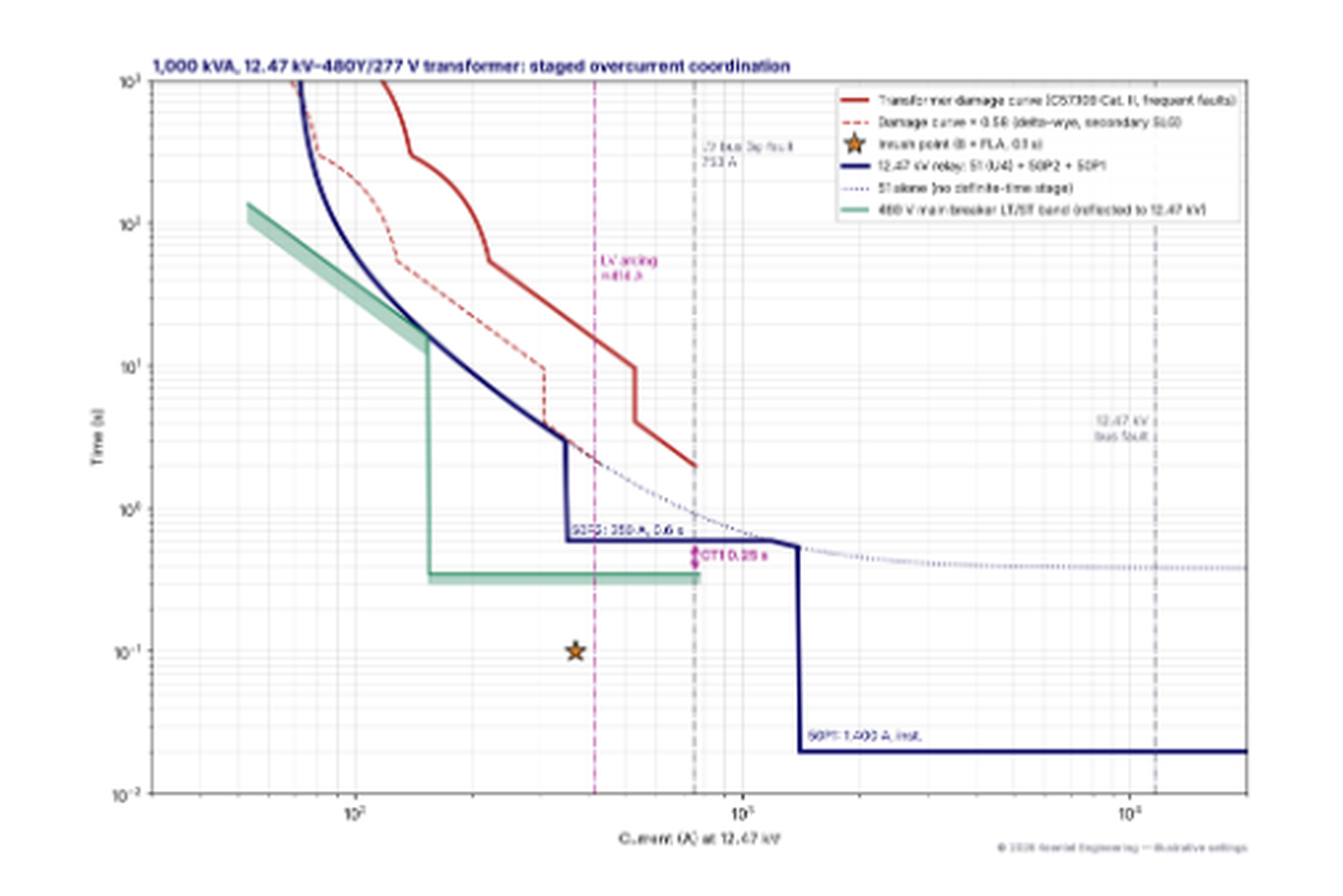
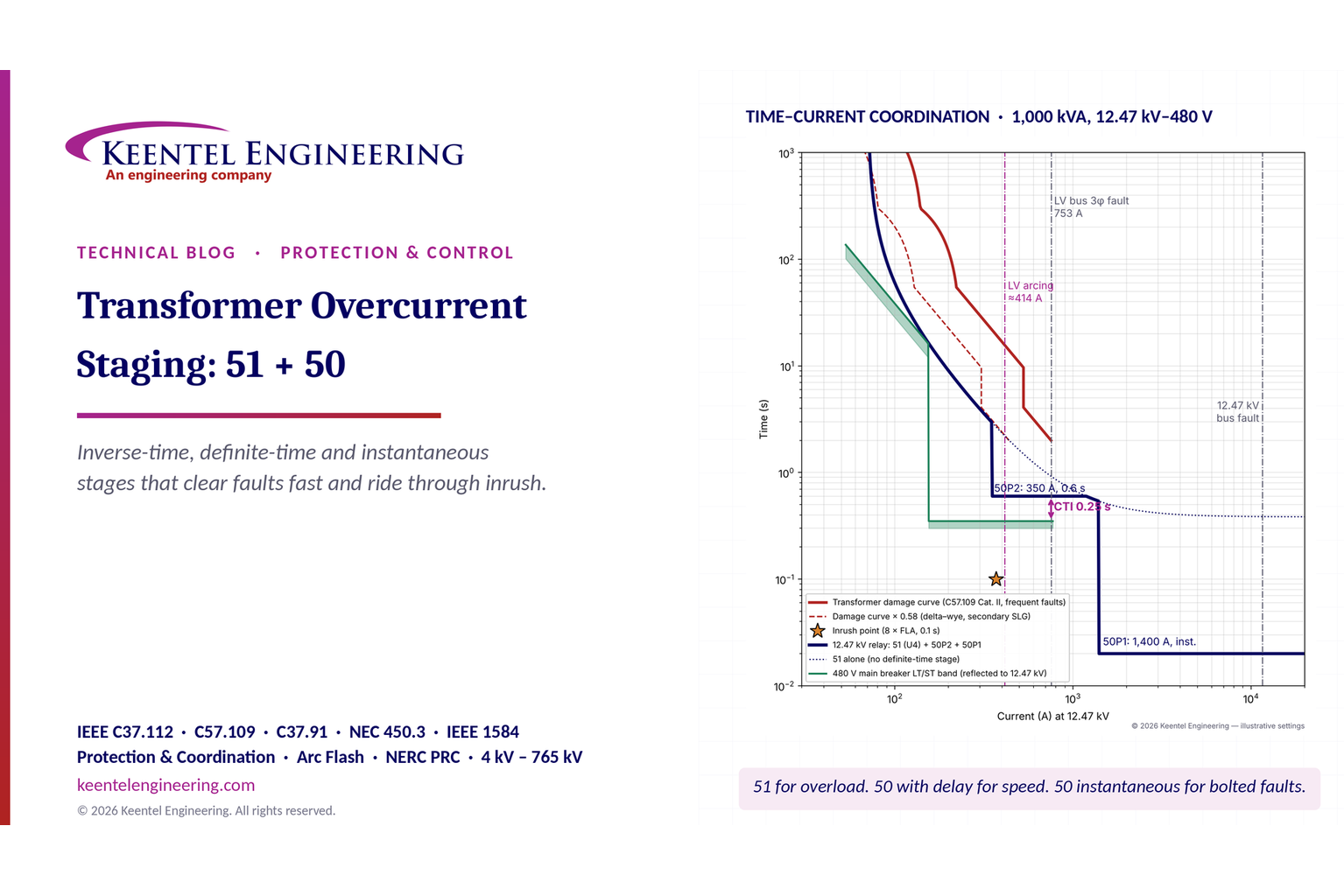
Figure 1 shows the complete coordination for Example 1. The rest of the guide builds it one stage at a time.

Figure 1. Time–current coordination for a 1,000 kVA, 12.47 kV–480Y/277 V transformer, plotted at 12.47 kV. The relay (navy) combines an extremely inverse 51 curve, a definite-time 50P2 stage at 350 A and 0.6 s, and an instantaneous 50P1 at 1,400 A. It stays below the C57.109 damage curve (red, solid and 58%-shifted dashed) and above the inrush point (star). It keeps a 0.25 s margin over the 480 V main breaker's short-time band (green). Illustrative settings only.
Part B — Staged Overcurrent Protection: An Engineering Guide
A transformer's HV overcurrent relay has to satisfy several requirements that pull in different directions:
- It must not trip on load. That includes the top cooling-stage rating, emergency overloads allowed by IEEE C57.91 and cold-load pickup after an outage.
- It must not trip on inrush. Energizing a transformer draws magnetizing current that can reach 8–12 times full-load current for the first few cycles.
- It must coordinate with the secondary main. A fault on a 480 V feeder or a 13.8 kV feeder should be cleared by the downstream device, with the transformer relay waiting as backup.
- It must clear faults before damage. Large through-faults stress the windings mechanically and thermally. The IEEE C57.109 damage curve sets the time limit.
- It should clear terminal faults fast. A fault between the transformer secondary and the secondary main breaker is seen only by the HV relay. On a delta–wye unit-substation transformer this zone often carries the highest arc-flash incident energy in the building.
A single inverse-time curve is a compromise among all of these. To coordinate with the secondary main, it must be slow at the currents a secondary fault produces. That same slowness lets a fault in the secondary throat (the zone the secondary main cannot clear) burn for seconds.
Staging breaks the compromise. The inverse curve handles overload and coordination at lower currents. A definite-time stage takes over at fault levels and holds a fixed, short delay. The instantaneous stage handles the very high currents that can only come from a fault on the HV side.
2. Device functions and terminology
US practice names protective functions with the ANSI/IEEE C37.2 device numbers. International literature often uses different terms for the same characteristics. The mapping below helps when reading relay manuals or settings sheets prepared to another convention.
| US term (ANSI device) | Common international term | Characteristic |
|---|---|---|
| 51 — AC inverse time overcurrent relay | IDMT (inverse definite minimum time) | Operating time decreases as current increases |
| 50 with intentional delay (50P2, 50P3) | DMT or DT (definite minimum time, definite time) | Fixed operating time above pickup |
| 50 — instantaneous overcurrent relay | High-set, instantaneous | No intentional delay; operates in about 1–2 cycles |
| 51N / 51G | Earth-fault IDMT | Inverse time on residual or neutral current |
| 50N / 50G | Earth-fault instantaneous | Instantaneous on residual or neutral current |
| 87T | Transformer differential | Compares currents entering and leaving the zone |
| 63 | Sudden pressure / Buchholz | Mechanical detection of internal faults |
| 86 | Lockout relay | Trips and blocks reclosing until reset by hand |
A microprocessor relay typically offers four or more phase overcurrent stages. Each stage can be set as instantaneous, definite-time or (on some relays) inverse-time. Each stage can also be torque-controlled by logic: blocked by second-harmonic restraint, enabled only in a maintenance mode, or supervised by a directional element.
In plain terms: "IDMT" and "51" describe the same thing. So do "DMT" and "50 with a time delay". What matters is the characteristic, the pickup and the time, not the label.
3. Inverse-time curves in US practice
3.1 The IEEE C37.112 equation
IEEE Std C37.112 defines the inverse-time characteristic used by US microprocessor relays:

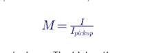
where t is the operating time in seconds, TD is the time dial, and M is the multiple of pickup current:

A, B and p are constants that set the curve's shape. The higher the exponent p, the more steeply the curve falls as current rises.
| Curve | A | B | p | Typical use |
|---|---|---|---|---|
| U1 — Moderately inverse | 0.0104 | 0.2256 | 0.02 | Sources with widely varying fault levels |
| U2 — Inverse | 5.95 | 0.180 | 2.0 | General purpose |
| U3 — Very inverse | 3.88 | 0.0963 | 2.0 | Feeders and transformers with a large fault-current drop along the circuit |
| U4 — Extremely inverse | 5.67 | 0.0352 | 2.0 | Coordinating with fuses and LV breaker long-time elements; riding through inrush and cold load |
| U5 — Short-time inverse | 0.00342 | 0.00262 | 0.02 | Fast backup, bus protection |
| C37.112 extremely inverse (standard set) | 28.2 | 0.1217 | 2.0 | Same purpose as U4 with different scaling |
The U-curve labels and constants above are used by many US relays and follow the electromechanical relay shapes. IEEE C37.112 publishes its own standard moderately inverse, very inverse and extremely inverse constants (for example A = 28.2, B = 0.1217, p = 2 for extremely inverse). Always confirm the constants in the relay manual before modeling, because the same name can carry different constants.
3.2 How the curves compare
The table gives operating times at time dial 1 for each U-curve:
| Curve | M = 2 | M = 5 | M = 10 | M = 20 |
|---|---|---|---|---|
| U1 | 0.971 s | 0.544 s | 0.446 s | 0.394 s |
| U2 | 2.163 s | 0.428 s | 0.240 s | 0.195 s |
| U3 | 1.390 s | 0.258 s | 0.135 s | 0.106 s |
| U4 | 1.925 s | 0.271 s | 0.0925 s | 0.0494 s |
| U5 | 0.248 s | 0.107 s | 0.075 s | 0.058 s |
The extremely inverse U4 curve is about 20 times faster at 10 times pickup than at 2 times pickup. That shape matches the I²t behavior of fuses, low-voltage breaker long-time elements and the transformer's own thermal damage curve. It is why U4 (or the C37.112 extremely inverse curve) is the most common choice for transformer HV relays that must coordinate with a 480 V main breaker.
3.3 International curves sometimes found in US relays
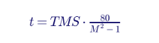
Many relays also offer the IEC 60255-151 curves. The IEC extremely inverse curve is:

At a time multiplier (TMS) of 2.74 and 10 times pickup, it gives 2.74 × 80/99 = 2.21 seconds. That is slow for a transformer relay in a US unit substation. If a settings file uses IEC curves, convert them carefully: TMS and TD are not interchangeable, and neither are the curve constants.
3.4 Reset characteristics
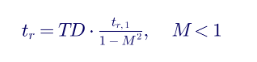
Electromechanical induction-disk relays reset slowly after current drops, because the disk must rotate back. Microprocessor relays can emulate that with the C37.112 reset equation:

4. The transformer through-fault damage curve
4.1 IEEE C57.109 categories
IEEE Std C57.109 defines through-fault capability curves for liquid-immersed transformers. It sorts transformers into four categories by minimum nameplate rating:
| Category | Three-phase rating | Single-phase rating | Curve shape |
|---|---|---|---|
| I | 15–500 kVA | 5–500 kVA | Thermal curve only |
| II | 501–5,000 kVA | 501–1,667 kVA | Thermal curve, plus a mechanical curve for frequent faults |
| III | 5,001–30,000 kVA | 1,668–10,000 kVA | Thermal curve, plus a mechanical curve for frequent faults |
| IV | Above 30,000 kVA | Above 10,000 kVA | Thermal and mechanical curves apply to all faults |
"Frequent faults" means more than about 10 (Category II) or 5 (Category III) through-faults over the transformer's life. Transformers serving overhead lines or industrial loads should normally be treated as frequent-fault units. Transformers feeding cable systems that rarely fault can use the infrequent-fault (thermal-only) curve.
4.2 The thermal curveA
The thermal portion follows a constant I²t, with current in per unit of base-rated current:
It is anchored at its low-current end by tabulated points: 2 pu for 1,800 seconds, 3 pu for 300 seconds and 4.75 pu for 60 seconds. Above 4.75 pu the I²t = 1250 line applies.
4.3 The mechanical curve
For Categories II and III with frequent faults, a mechanical curve applies at high currents. It also follows constant I²t, but is anchored at 2 seconds at the maximum through-fault current:

Here Z_t is the per-unit impedance (transformer plus source for Categories III and IV; transformer only for Category II in the strict reading, although many engineers include the source for a more accurate curve) and I is the current in per unit. At I = 1/Z_t, the maximum through-fault current, t = 2 seconds.
The mechanical curve begins at 70% of maximum fault current for Category II and at 50% for Category III. At that point, the curve steps down from the thermal curve, which is why damage curves show a vertical jump.
4.4 The 58% shift for delta–wye transformers
On a delta–wye transformer, a single-line-to-ground fault on the wye secondary produces a primary line current of only 1/√3, or 0.577, of the per-unit winding current. The HV relay sees less current than the winding actually carries.
To make sure the HV relay still protects the winding, the damage curve plotted on the primary side is shifted left to 58% of its current values for this case. Figure 1 shows both curves.
Worked Example 1 — Damage curve for the 1,000 kVA transformer
Full-load current on the 12.47 kV side is:

On the 480 V side, it is 1,202.8 A.
Including the 250 MVA source (0.004 pu on a 1 MVA base), the total impedance is:
so the maximum through-fault current is 1/0.0615 = 16.26 pu, or 752.8 A at 12.47 kV.
| Point | Current (pu) | Current at 12.47 kV | Time |
|---|---|---|---|
| Thermal anchor | 2.0 | 92.6 A | 1,800 s |
| Thermal anchor | 3.0 | 138.9 A | 300 s |
| Thermal anchor | 4.75 | 219.9 A | 60 s (I²t line gives 55 s) |
| Thermal (I²t = 1250) | 6.3 | 291.7 A | 31.5 s |
| Thermal (I²t = 1250) | 11.3 | 523.2 A | 9.8 s |
| Mechanical starts (70% of max) | 11.38 | 527 A | Steps down to about 4.1 s |
| Maximum through-fault | 16.26 | 752.8 A | 2.0 s |
For a secondary ground fault, every current in the table is multiplied by 0.58. For example, the 2-second point moves from 752.8 A to about 437 A. The HV relay must clear below both curves.
5. Magnetizing inrush and cold-load pickup
5.1 The inrush point
When a transformer is energized, its core can be driven into saturation, drawing a magnetizing current many times rated current. The current is highly asymmetric, rich in second harmonic and decays over a few tenths of a second to several seconds.
For coordination, US practice represents inrush by one point on the TCC:
- 8 times full-load current at 0.1 second for transformers up to about 3 MVA.
- 12 times full-load current at 0.1 second for larger transformers.
Some engineers add a second point at 25 times full-load current at 0.01 second. Every overcurrent stage must plot above and to the right of the inrush point.
For the 1,000 kVA example:

5.2 Second-harmonic blocking
Inrush current typically contains 15–60% second harmonic, while fault current contains very little. Most transformer relays can block or restrain fast overcurrent stages when second harmonic exceeds a threshold (commonly 15–20% of fundamental).
Second-harmonic blocking lets a definite-time or instantaneous stage be set below the inrush point. Modern low-loss cores with high-permeability steel can produce inrush with less than 15% second harmonic, so blocking thresholds should be checked against energization records or EMT studies.
5.3 Sympathetic inrush and cold-load pickup
Two related events also need attention:
- Sympathetic inrush: energizing one transformer can drive a parallel, already-energized transformer into saturation. Both relays see inrush-like currents that decay slowly.
- Cold-load pickup: after an outage, thermostatically controlled loads all restart at once. Current can stay at 2–3 times normal load for several seconds to minutes.
A 51 pickup at 125–200% of rated current, with an extremely inverse curve, usually rides through cold load. A definite-time stage set just above full-load current would not.
How Keentel helps here: where inrush or sympathetic interaction is uncertain, we run EMT energization studies with realistic residual flux and point-on-wave closing. The results set harmonic-blocking thresholds and definite-time pickups from data, not from rules of thumb.
6. NEC limits for transformer overcurrent protection
For transformers over 1000 V, NEC Section 450.3(A) and Table 450.3(A) (2023 edition; earlier editions used 600 V as the threshold) set the maximum rating or setting of overcurrent protection, as a percentage of transformer rated current.
| Transformer impedance | Primary (over 1000 V): breaker | Primary: fuse | Secondary over 1000 V: breaker | Secondary over 1000 V: fuse | Secondary 1000 V or less: breaker or fuse |
|---|---|---|---|---|---|
| 6% or less | 600% | 300% | 300% | 250% | 125% |
| More than 6%, up to 10% | 400% | 300% | 250% | 225% | 125% |
In supervised locations (where conditions of maintenance and supervision ensure only qualified persons service the installation), primary-only protection is allowed at 300% (breaker) or 250% (fuse). Notes to the table allow the next higher standard rating or setting in some cases and permit a higher secondary setting where a differential relay protects the transformer.
For relay-operated breakers, "setting" means the pickup of the time-overcurrent element. For Example 1:
| Limit | Calculation | Value | Selected setting |
|---|---|---|---|
| Primary breaker (Z ≤ 6%) | 6.00 × 46.30 A | 277.8 A | 51 pickup 70 A (complies) |
| Secondary 480 V | 1.25 × 1,202.8 A | 1,503.5 A | Main breaker long-time pickup 1,250 A (complies) |
Two other NEC requirements shape the 480 V side:
- Section 240.87 (arc energy reduction): a breaker rated or adjustable to 1,200 A or more must have a method to reduce clearing time, such as zone-selective interlocking, differential relaying, an energy-reducing maintenance switch or an active arc-flash mitigation system.
- Sections 230.95 and 215.10 (ground-fault protection of equipment): a solidly grounded wye service or feeder above 150 V to ground and not over 1000 V phase-to-phase, with a disconnect rated 1,000 A or more, needs ground-fault protection.
Neither requirement covers the zone between the transformer secondary bushings and the secondary main. That zone is protected only by the HV relay, which is why its staging matters so much.
How Keentel helps here: our coordination studies include an NEC 450.3, 240.87 and 230.95 compliance table for every transformer, so the authority having jurisdiction and the owner can see each limit and the setting that meets it.
7. Fault currents that set the stages
Worked Example 2 — Fault currents for the 1,000 kVA transformer
The source contributes 0.004 pu on the 1 MVA base (250 MVA available). A bolted three-phase fault on the 480 V terminals gives:

With an infinite source, the same fault gives 20,918 A. The current the HV relay sees for that fault is reflected through the turns ratio:

The full set of currents used for the settings:
| Quantity | Value | Use |
|---|---|---|
| Full-load current, 12.47 kV | 46.30 A | 51 pickup, NEC limit |
| Full-load current, 480 V | 1,202.8 A | Secondary main sizing |
| 480 V bolted three-phase fault | 19,558 A (20,918 A infinite bus) | Secondary main interrupting rating, arc flash |
| Through-fault at 12.47 kV (three-phase) | 752.8 A (805 A infinite bus) | 50P1 floor, damage curve |
| First-cycle asymmetric through-fault (× 1.6) | 1,205 A (1,288 A infinite bus) | 50P1 must stay above |
| 480 V arcing fault (IEEE 1584-2018, typical switchgear) | About 10.76 kA | Arc-flash clearing time |
| Arcing fault reflected to 12.47 kV | About 414 A | 50P2 must pick up below this |
| Arcing fault at 85% variation | About 352 A | 50P2 should still pick up |
| 12.47 kV bus three-phase fault | 11,575 A | CT selection, 50P1 operation |
| 12.47 kV bus single-line-to-ground (example grounding) | 434 A | 51N/50N on the source side |
| Inrush (8 × FLA, 0.1 s) | 370 A | Floor for fast stages |
Using the transformer's nameplate impedance minus its tolerance (typically 7.5% per IEEE C57.12.00 for two-winding units) gives a slightly higher through-fault current. A careful 50P1 setting uses that lower bound.
7.1 What the arcing fault means for staging
The arcing current reflected to the HV side (about 414 A) is barely more than half the bolted through-fault current. On a single extremely inverse curve that is coordinated with the secondary main, 414 A falls in the slow part of the curve. That is the gap a definite-time stage closes.
8. Current transformer selection
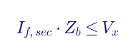
The CT ratio decides whether the relay can see the currents it is set for. IEEE C37.110 gives the rule for avoiding saturation on symmetrical fault current:

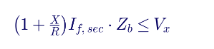
and, to avoid saturation even with full DC offset:
where I_f,sec is the secondary fault current, Z_b the total burden (leads, relay and CT winding) and V_x the CT's C-class knee-point rating.
Worked Example 3 — Choosing a CT ratio for the 12.47 kV relay
A 100:5 CT looks natural for a 46 A full-load current. But a 12.47 kV bus fault of 11,575 A would drive 579 A secondary, 116 times the CT rating. The CT would saturate heavily, and the fast stages are the ones that suffer.
A 600:5 multi-ratio CT, C200, on its full tap gives:
| Setting | Primary | Secondary (600:5) |
|---|---|---|
| 51 pickup | 70 A | 0.58 A |
| 50P2 pickup | 350 A | 2.92 A |
| 50P1 pickup | 1,400 A | 11.67 A |
| 12.47 kV bus fault | 11,575 A | 96.5 A (19.3 × rated) |
With 0.5 Ω total burden, the symmetrical check gives 96.5 × 0.5 = 48 V, well below 200 V. The full-offset check (X/R of 10) gives about 530 V, so DC saturation is possible in the first cycles. That is normally acceptable for instantaneous elements in microprocessor relays, which measure fundamental current and operate before deep saturation. It should be confirmed against the relay manufacturer's CT requirements.
The 0.58 A pickup must fall within the relay's setting range for a 5 A nominal input. Most US relays accept it, but confirm.
In plain terms: pick the CT from the fault current, then check the pickup range. Picking it from load current alone is a common cause of slow or failed instantaneous trips.
9. Setting each stage
9.1 The 51 inverse-time stage
The 51 stage is set in three steps:
- Pickup: 125–200% of the transformer's maximum rated current (top cooling stage). This must also meet NEC 450.3, sit above cold-load current and leave room for permitted overloads.
- Curve: usually extremely inverse, to track the secondary main's long-time band and the damage curve.
- Time dial: the lowest value that keeps the required coordination time interval (CTI) over the downstream device at every current where both operate.
The CTI between a relay-operated breaker and a downstream low-voltage breaker is usually 0.2–0.3 second. It covers breaker clearing time, relay overtravel (zero in microprocessor relays) and setting and CT errors. Between two relay-operated breakers, 0.2–0.3 second is common; with electromechanical relays, 0.3–0.4 second.
9.2 The 50P2 definite-time stage
The definite-time stage is the one that most improves protection on small and mid-size transformers. It is set by:
- Pickup: above the inrush point (or below it, if second-harmonic blocking is enabled and verified) and above cold-load current. It should also be below the minimum reflected arcing fault current at the secondary terminals.
- Delay: the secondary main's short-time clearing time plus the CTI.
9.3 The 50P1 instantaneous stage
The instantaneous stage is set by one rule: it must never operate for a fault on the secondary side. US practice sets its pickup at least 1.6 times the maximum symmetrical through-fault current (some engineers use 1.7–2.0, or 1.25 with relays that filter DC offset). It must also exceed the inrush current at 0.01–0.1 second and still pick up reliably for an HV terminal fault at minimum source strength.
Worked Example 4 — Complete settings for the 1,000 kVA transformer
The downstream device. The 480 V main breaker has a trip unit with long-time pickup 1,250 A, long-time delay 4 s at 6 times pickup (I²t, +15% tolerance band) and short-time pickup 4,000 A at 0.3 s (clearing by 0.35 s). Its instantaneous function is off so the feeders below can coordinate.
Step 1 — 51 stage.
- Pickup: 70 A, which is 151% of full-load current and well under the NEC 600% limit of 277.8 A.
- Curve: U4 extremely inverse.
- Time dial: the main breaker's long-time band ends at its short-time pickup (4,000 A, which reflects to 154 A at 12.47 kV). The closest approach is near that corner. A time dial of 10.9 keeps the 51 curve above the main's upper long-time band everywhere: 59.8 s against 38.3 s at 100 A and 17.6 s against 17.0 s at 150 A (the tightest point, where margin is also set by the steeper slope of the relay curve).
Step 2 — 50P2 stage.
- Pickup: 350 A (7.6 times full-load current). It sits below the reflected arcing current of 414 A and essentially at the 85% arcing variation of 352 A.
- Delay: 0.6 s. The main breaker's short-time band clears by 0.35 s, so the CTI is 0.25 s.
- Inrush check: at 370 A, the relay waits 0.6 s, well above the 0.1 s inrush point. Inrush current falls quickly below 350 A for a transformer this size, but if energization records show a slow decay, enable second-harmonic blocking on 50P2.
Step 3 — 50P1 stage.
- Pickup: 1,400 A. That is 1.86 times the 752.8 A through-fault and above the 1,288 A worst-case asymmetric through-fault with an infinite source.
- Delay: none (relay operating time about 0.02 s, plus breaker).
- Dependability: the 12.47 kV bus fault of 11,575 A is 8.3 times pickup.
The resulting operating times:
| Current at 12.47 kV | Relay operating time | 480 V main breaker (reflected) | Margin |
|---|---|---|---|
| 100 A | 59.8 s (51) | 38.3 s (long-time, upper band) | 21.5 s |
| 150 A | 17.6 s (51) | 17.0 s (long-time, upper band) | 0.6 s |
| 200 A | 9.0 s (51) | 0.35 s (short-time) | 8.7 s |
| 300 A | 3.94 s (51) | 0.35 s | 3.6 s |
| 350–1,400 A | 0.60 s (50P2) | 0.35 s | 0.25 s |
| Above 1,400 A | 0.02 s (50P1) | Fault is on the HV side | — |
Damage check.
At the maximum through-fault of 752.8 A, the relay clears in 0.6 s plus breaker time, against 2.0 s on the damage curve. At the 58%-shifted 2-second point (437 A), it clears in the same 0.6 s. Across the 51 range, the relay curve stays below the shifted thermal curve.
What the definite-time stage buys.
With 51 alone, the relay would take 0.85 s at the maximum through-fault and 2.67 s at the inrush current. Adding 50P2 leaves the overload and coordination behavior unchanged and cuts the time for every fault between 350 A and 1,400 A to 0.6 s.
How Keentel helps here:
we deliver settings like these as a complete package: the coordination study report, annotated TCC plots, the relay setting file in the manufacturer's format, a settings summary table and a test plan for the field technician.
10. Arc-flash incident energy and staging
Under IEEE 1584-2018, incident energy at a given working distance is close to proportional to arcing time. For a fault on the 480 V transformer terminals or the line side of the secondary main, the arcing time is the HV relay's operating time plus the HV breaker's interrupting time.

Worked Example 5 — Arc-flash benefit of the 50P2 stage
For the 1,000 kVA example, the 480 V arcing current is about 10.76 kA, which reflects to about 414 A at 12.47 kV. With a 5-cycle (0.083 s) HV breaker:
| Protection | Relay time at 414 A | Total clearing time | Relative incident energy |
|---|---|---|---|
| 51 alone | 2.21 s | 2.29 s | 100% |
| 51 + 50P2 | 0.60 s | 0.68 s | About 30% |
| 51 alone, at 85% arcing current (352 A) | 2.93 s | 3.01 s | 131% |
| 51 + 50P2, at 85% arcing current | 0.60 s | 0.68 s | About 30% |
The definite-time stage cuts arcing time, and therefore incident energy, by about 70%. IEEE 1584-2018 caps the arc duration used in calculations at 2 seconds where a worker can reasonably escape, but that cap is a judgment call, not a protection scheme.
The margin between the 85% arcing current (352 A) and the 50P2 pickup (350 A) is thin. Several options can widen it:
- Lower 50P2 with second-harmonic blocking, after confirming inrush harmonic content.
- Add a maintenance-mode stage, such as a 50P3 at 250 A with 0.05 s delay, enabled only while workers are present, through a selector switch or SCADA bit with status indication.
- Add transformer differential (87T) covering the secondary throat, or an arc-flash detection relay using light plus current.
- Use a low-impedance secondary main with zone-selective interlocking, which helps downstream equipment but not the throat itself.
How Keentel helps here: Keentel performs arc-flash studies to IEEE 1584-2018 and NFPA 70E, with labels, a mitigation report and before-and-after incident energy for each option. We often find that one added relay stage removes the highest-energy labels in a facility at almost no hardware cost.
11. Staging on a larger substation transformer
Worked Example 6 — 20/27/33 MVA, 115–13.8 kV transformer
Ratings and currents.
| Quantity | Value |
|---|---|
| HV full-load current | 100.4 A at 20 MVA; 165.7 A at 33 MVA |
| LV full-load current | 836.7 A at 20 MVA; 1,380.6 A at 33 MVA |
| Total impedance (transformer 0.10 pu plus source 0.005 pu, 20 MVA base) | 0.105 pu |
| 13.8 kV bus three-phase fault | 7,967 A |
| Through-fault seen at 115 kV | 956 A |
| Inrush (12 × 20 MVA FLA, 0.1 s) | 1,205 A |
| C57.109 category | III (frequent faults) |
| Mechanical curve | Starts at 0.5/Z_t = 4.76 pu (478 A) at 8 s; ends at 9.52 pu (956 A) at 2 s |
Primary protection. At this size the transformer has 87T differential and a 63 sudden-pressure relay, both tripping an 86 lockout. The 50/51 relay on the 115 kV breaker is backup.
Downstream device. The 13.8 kV main breaker relay uses a 51 at 1,600 A (116% of the 33 MVA rating) on a 2000:5 CT, U3 very inverse, time dial 2.0. It operates in 0.52 s for a 13.8 kV bus fault.
HV relay settings (CT 600:5).
- 51 pickup: 1.5 × 165.7 A = 248.5 A (2.07 A secondary), U3 very inverse to match the 13.8 kV main.
- Time dial: at the 956 A through-fault, the main operates at 0.52 s, so the HV relay needs at least 0.82 s. U3 at TD 1 gives 0.377 s at M = 3.85, so TD = 2.2 gives 0.83 s.
- 50P1 pickup: at least 1.6 × 956 A = 1,530 A. Choose 1,800 A, which is also above the 1,205 A inrush point.
| 13.8 kV fault current | Reflected to 115 kV | 13.8 kV main | 115 kV 51 | Margin |
|---|---|---|---|---|
| 3,000 A | 360 A | 3.28 s | 7.98 s | 4.7 s |
| 4,000 A | 480 A | 1.67 s | 3.34 s | 1.67 s |
| 6,000 A | 720 A | 0.79 s | 1.37 s | 0.58 s |
| 7,967 A | 956 A | 0.52 s | 0.83 s | 0.31 s |
Damage check. At 478 A, the mechanical curve allows 8 s and the relay clears in about 3.4 s. At 956 A, the curve allows 2 s and the relay clears in 0.83 s. With the 58% shift for a 13.8 kV ground fault, the 2-second point moves to about 555 A, where the 51 operates in about 2.4 s. That is the one place the backup overcurrent relay does not fully protect the transformer on its own, and it is covered by 87T and the 13.8 kV ground relays.
Would a definite-time stage help? Here, very little. The secondary-side fault current range is narrow (the through-fault is only 3.85 times the 51 pickup), the 13.8 kV main's own operating time sets the floor, and 87T already clears internal and throat faults in about 1.5 cycles. The definite-time stage earns its place mainly on transformers without differential protection, which in US practice usually means units below about 10 MVA.
In plain terms: on a small unit substation, the HV overcurrent relay is the transformer's main protection, and staging is the cheapest way to make it fast. On a large substation transformer, differential relaying does that job, and overcurrent staging is mostly about clean backup.
12. Ground-fault protection and winding connections
The winding connection decides what a ground relay on each side can see:
- Delta primary: a ground fault on the grounded-wye secondary produces no zero-sequence current on the delta side. The HV phase relays see it only as reduced phase current (the 58% case). An HV 51N on a delta winding sees only ground faults on the HV system and the HV leads.
- Grounded-wye secondary: a neutral CT (51G) on the transformer neutral sees every secondary ground fault, including faults in the throat between the transformer and the secondary main. On a 480 V system it should coordinate with the main's ground-fault (G) function.
- Resistance-grounded secondary: on low-resistance grounded 4.16 kV or 13.8 kV systems, the neutral resistor limits ground-fault current (often to 200–400 A at 4.16 kV and up to about 2,000 A at 13.8 kV). The 51G must be set below the resistor's let-through current, coordinated with feeder ground relays and fast enough to protect the resistor's time rating.
- Grounded-wye to grounded-wye: zero-sequence current passes through, so ground relays on both sides interact and must be coordinated together.
A neutral 51G with a definite-time stage set at 20–30% of the resistor or available ground-fault current, with a delay of 0.3–0.5 s above the secondary main's ground function, is a common and effective way to protect the throat for ground faults.
How Keentel helps here: we review grounding and ground-fault protection as one system, from transformer neutral to feeder ground relays and NEC 230.95 ground-fault protection of equipment, including resistor ratings and alarm-versus-trip decisions for high-resistance grounded systems.
13. Where NERC requirements apply
For transformers that are part of the Bulk Electric System (BES) or that serve BES generation, several NERC Reliability Standards touch overcurrent staging:
| Standard | What it requires | Relevance to transformer overcurrent |
|---|---|---|
| PRC-005 | Protection system maintenance and testing at set intervals | Relays, CTs, DC supply and trip paths for BES transformer protection must be tested on schedule |
| PRC-027 | Coordination of protection systems for performance during faults | Settings changes on BES elements need a documented coordination review, including short-circuit data |
| PRC-023 | Transmission relay loadability | Phase overcurrent elements on certain transformers must not trip on specified overload levels |
| PRC-019 | Coordination of generating unit voltage controls, limiters and protection | GSU and auxiliary transformer overcurrent must coordinate with generator capability and limiters |
| PRC-024 | Generator frequency and voltage protective relay settings | Ride-through requirements limit how fast certain protection may trip generating facilities |
| MOD-032, MOD-033 | Modeling data and validation | Short-circuit and system models used for settings must be consistent with planning models |
Whether a particular 115–13.8 kV distribution transformer falls in scope depends on the BES definition and the registered entity's documented decisions. A distribution transformer is usually excluded, but its relays can still be in PRC-005 scope if they trip BES elements. Confirm applicability with the transmission owner and the compliance group.
How Keentel helps here: Keentel supports PRC-027 coordination reviews, PRC-005 program documentation, PRC-023 loadability checks and PRC-019/PRC-024 generator protection studies, with evidence packages organized the way auditors expect.
14. Testing and commissioning the stages
Good settings are only as good as their implementation. A site acceptance test (SAT) for a staged overcurrent relay should include:
- Settings verification: compare the loaded settings file against the approved settings, line by line, including CT ratios, curve types, time dials and logic.
- Pickup tests: inject current at each stage's pickup and confirm operation within the stated tolerance (typically ±5%).
- Timing tests: inject at least three multiples on the 51 curve (for example 2, 5 and 10 times pickup) and confirm operating time against the C37.112 equation. Inject above the 50P2 and 50P1 pickups and confirm their fixed times.
- Stage interaction: confirm that 50P2 overrides the slower 51 curve above its pickup and that 50P1 overrides both.
- Harmonic blocking: inject fundamental plus second harmonic above and below the blocking threshold and confirm the expected behavior.
- CT checks: ratio, polarity, insulation resistance, excitation (saturation) curve and secondary burden.
- Trip path: functional trip of the breaker from each stage, through any lockout, with breaker clearing time recorded.
- In-service check: once energized, verify phase currents and angles at the relay against expected load.
The first energization is also a free inrush test. Capture the event record and confirm the measured inrush magnitude, decay and second-harmonic content against the assumptions used in the settings.
How Keentel helps here: our field engineers perform relay SAT and commissioning for MV switchgear and substation transformers, with test reports, as-left settings files and PRC-005 baseline records.
15. Settings checklist
Before issuing settings for a transformer HV overcurrent relay, confirm:
- Ratings: top cooling-stage rating, impedance and tolerance, winding connection and C57.109 category.
- Fault study: maximum and minimum source strength, secondary three-phase and ground faults, HV bus faults, arcing currents per IEEE 1584-2018.
- CTs: ratio, accuracy class and burden checked per IEEE C37.110 against maximum fault current.
- 51: pickup within 125–200% of maximum rated current and within NEC 450.3; curve and time dial set from CTI against the secondary main across its range.
- 50P2: pickup above inrush (or harmonic blocking verified) and below the minimum reflected arcing current; delay set from the secondary main's short-time band plus CTI.
- 50P1: pickup at least 1.6 times the maximum through-fault current and above inrush; still dependable for an HV terminal fault at minimum source.
- Damage curve: all stages below the C57.109 curve, including the 58% shift for delta–wye units.
- Ground: 51N/51G settings match the winding and grounding arrangement.
- Arc flash: incident energy calculated with the final settings, labels updated, NEC 240.87 method documented.
- Compliance: NERC applicability checked and records prepared.
- Testing: test plan issued with each stage's pickup and timing points.
Part C — Case Studies
The three case studies below are drawn from typical project experience. Names, locations and identifying details have been removed, and values have been rounded.
Case Study 1 — A unit substation that tripped on every energization
Situation. A manufacturing plant in the Southeast had a 2,000 kVA, 13.2 kV–480Y/277 V unit-substation transformer that tripped its primary breaker roughly one time in three on energization. Each trip meant a delayed restart and a call to the electrical contractor.
Findings
The relay had been set by copying a template from another site. Its definite-time stage was set at 3 times full-load current with 0.1 s delay, well below the 8-times inrush point. The 51 pickup was 90% of full-load current, so the relay was also timing on heavy production loads.
Solution
Keentel rebuilt the coordination from a new fault study. The 51 pickup moved to 150% of full-load current with an extremely inverse curve. The definite-time stage moved above inrush with a delay coordinated to the 480 V main's short-time band, and second-harmonic blocking was enabled with a threshold confirmed from an event record. The instantaneous stage was raised to 1.7 times the through-fault current.
Result
The transformer has energized without a trip since the change. The arc-flash study, rerun with the new settings, confirmed that incident energy at the 480 V switchgear line side stayed within the existing PPE category, because the corrected definite-time stage still clears terminal arcing faults in well under a second.
Case Study 2 — Reducing arc-flash energy at a data center electrical room
Situation
A colocation data center in the Mid-Atlantic had eight 2,500 kVA, 12.47 kV–480Y/277 V transformers feeding switchboards. The arc-flash study showed incident energy above 40 cal/cm² on the line side of every 480 V main, driven by the HV relays' extremely inverse curves, which took more than 2 seconds to clear a terminal arcing fault.
Findings
The HV relays had only 51 and 50P1 enabled. The instantaneous stage could not see the secondary arcing fault, and the 51 curve had been set slow to coordinate with the 480 V mains' long-time bands.
Solution
Keentel added a definite-time stage to each relay, set between inrush and the minimum reflected arcing current, with a delay coordinated to the mains' short-time bands. Because the margin at 85% arcing current was tight, a maintenance-mode stage with near-instantaneous operation was also added, enabled by a labeled selector switch with status shown on the facility's monitoring system. The NEC 240.87 documentation was updated to describe both methods.
Result
Normal-mode incident energy at the 480 V line side dropped by roughly two-thirds, and maintenance-mode energy fell below 8 cal/cm². No hardware other than selector switches and wiring was required.
Case Study 3 — Backup protection review for a 138 kV substation transformer
Situation
A municipal utility in the Midwest owned a 30/40/50 MVA, 138–13.8 kV transformer whose 138 kV breaker relay was flagged in a PRC-027 coordination review after a nearby generation addition raised fault levels.
Findings
The higher source strength raised the maximum through-fault current enough that the instantaneous stage's margin had dropped to 1.2 times the symmetrical through-fault current. A 13.8 kV bus fault with high DC offset could have tripped the 138 kV breaker instead of the 13.8 kV main. The 51 curve was also above the 58%-shifted damage curve over part of its range.
Solution
Keentel updated the short-circuit model, raised the 50P1 pickup to 1.7 times the new through-fault current, changed the 51 curve and time dial to restore the CTI with the 13.8 kV main, and confirmed that 87T covered the remaining damage-curve gap. The study package included the PRC-027 documentation and updated PRC-005 test records.
Result
The utility closed the coordination finding with a complete evidence package and avoided a misoperation risk that would have dropped the entire 13.8 kV substation for a single feeder fault.
Part D — 20-Question Technical FAQ
1. What is the difference between a 50 and a 51 element?
A 51 element is inverse-time: its operating time decreases as current increases. A 50 element operates once current exceeds its pickup, either with no intentional delay (instantaneous) or after a fixed delay (definite-time).
2. Are IDMT and 51 the same thing?
Yes, in practice. IDMT (inverse definite minimum time) is the international name for an inverse-time overcurrent characteristic. US practice calls it device 51 and uses IEEE C37.112 curves such as moderately, very and extremely inverse.
3. How much more support does a STATCOM give during a voltage sag?
It caps the operating time for a known range of fault currents. On a transformer without differential protection, it cuts the clearing time for secondary terminal and throat faults from seconds to a fraction of a second, without changing overload behavior or coordination at lower currents.
4. Is a STATCOM always faster than an SVC?
Usually at 125–200% of the transformer's maximum rated current, high enough to carry permitted overloads and cold-load pickup and low enough to meet NEC 450.3 and protect the transformer. A pickup below full-load current is an error.
5. Why must the instantaneous stage be set at 1.6 times the through-fault current?
A fault on the secondary can carry a DC offset that raises the first-cycle current by up to about 60% above its symmetrical value. The 1.6 factor keeps the instantaneous stage from tripping for a fault the secondary main should clear.
6. What is the inrush point and why does it matter?
It represents transformer magnetizing inrush on the TCC: 8 times full-load current at 0.1 s for units up to about 3 MVA and 12 times for larger units. Every stage must plot above and to the right of it, or be blocked by second-harmonic restraint.
7. Should I enable second-harmonic blocking on overcurrent stages?
It is useful on definite-time and instantaneous stages set near inrush levels. Confirm the threshold against actual energization records, because modern cores can produce inrush with lower second-harmonic content.
8. Which curve is best for transformer protection?
Extremely inverse is the most common choice when the transformer feeds a low-voltage breaker or fuses, because its shape matches their I²t behavior and the damage curve. Very inverse is common where the downstream device is another relay with a very inverse curve.
9. What CTI should I use?
Typically 0.2–0.3 s between a relay-operated breaker and a downstream breaker with microprocessor relays or LV trip units. Use 0.3–0.4 s where electromechanical relays are involved, and check breaker clearing times.
10. What is the C57.109 damage curve?
It is the IEEE through-fault capability curve for liquid-immersed transformers. It defines how long a transformer can carry a given through-fault current, with a thermal portion for all categories and a mechanical portion for larger units and frequent faults.
11. Why shift the damage curve to 58%?
On a delta–wye transformer, a secondary single-line-to-ground fault appears on the primary at only about 58% of the per-unit winding current. Shifting the curve makes sure the HV relay still protects the winding for that fault.
12. Does NEC 450.3 apply to relay settings?
Yes. Table 450.3(A) sets the maximum rating or setting of overcurrent protection for transformers over 1000 V. For a relay-operated breaker, the relevant value is the time-overcurrent pickup.
13. Is a definite-time stage needed on large substation transformers?
Usually not. Transformers above about 10 MVA normally have 87T differential and sudden-pressure protection, which clear internal and throat faults much faster. Overcurrent on those units is backup and is set mainly for clean coordination.
14. How does staging reduce arc-flash energy?
Incident energy is close to proportional to arcing time. A definite-time stage that clears a secondary terminal arcing fault in 0.6 s instead of more than 2 s cuts incident energy by about 70% at that location.
15. Does NEC 240.87 cover the transformer secondary throat?
No. NEC 240.87 applies to circuit breakers rated or adjustable to 1,200 A or more and their downstream zone. The zone between the transformer and the secondary main is protected only by the HV relay, so HV staging, 87T or arc-flash detection are the usual mitigation methods.
16. How should CTs be sized for transformer overcurrent relays?
Choose the ratio from the maximum fault current and accuracy class, then confirm that the pickups fall within the relay's setting range. IEEE C37.110 gives the saturation checks.
17. What is a maintenance-mode overcurrent stage?
It is an extra fast stage, enabled only while people work on energized equipment. It trades selectivity for speed during that period and is one of the methods recognized for arc-energy reduction. It needs clear status indication and procedures for turning it off.
18. How do winding connections affect ground-fault protection?
A delta winding blocks zero-sequence current, so an HV ground relay on a delta primary cannot see secondary ground faults. Secondary ground faults are best detected by a neutral CT (51G) on the grounded wye winding.
19. When do NERC standards apply to transformer overcurrent settings?
When the transformer or the elements its relays trip are part of the Bulk Electric System, or when it serves BES generation. PRC-005, PRC-027, PRC-023, PRC-019 and PRC-024 can apply. Confirm scope with the registered entity.
20. How often should transformer relay settings be reviewed?
After any significant change in fault level, load, transformer, CT or downstream device, and at least every five years under NFPA 70E for arc-flash studies. NERC-registered entities follow their PRC-005 and PRC-027 programs
How Keentel Engineering Helps
Keentel Engineering is a US power system engineering firm that designs, studies and commissions protection for utilities, independent power producers, data centers, industrial plants and campuses, from 4 kV distribution to 765 kV transmission. For transformer protection, our services include:
- Protective device coordination studies: fault studies and TCC coordination using industry-standard coordination software, covering every relay, fuse and low-voltage trip unit from the utility source to the largest downstream feeder.
- Relay settings development: complete settings for 50/51, 50N/51N, 51G, 87T, 63 and lockout logic, delivered as manufacturer-format files with a settings summary and rationale.
- Arc-flash studies: IEEE 1584-2018 calculations, NFPA 70E labels, NEC 240.87 documentation and mitigation options with before-and-after incident energy.
- Short-circuit and EMT studies: maximum and minimum fault current, DC offset, CT saturation and transformer energization studies for inrush and sympathetic interaction.
- NERC compliance support: PRC-027 coordination reviews, PRC-005 program and test records, PRC-023 loadability checks and PRC-019/PRC-024 generator protection studies.
- SAT and commissioning: relay and CT testing, trip path verification and as-left records for MV switchgear and substation transformers.
- Owner's engineer services: settings review for utility interconnections, design review of protection and control packages and independent verification of contractor settings.
- Substation and switchgear design: protection and control design, one-lines, three-lines and relay panel layouts for AIS, GIS and metal-clad switchgear.
Why Clients Choose Keentel
- Study, settings and field work under one roof: the engineers who run the coordination study also write the settings and support the testing.
- US standards fluency: daily work with IEEE, NEC, NFPA 70E, NESC and NERC requirements.
- Independent advice: we are not tied to any relay or equipment supplier, so recommendations follow the engineering.
- Practical deliverables: clear TCCs, auditable calculations, ready-to-load settings files and test plans.
- Full voltage range: from 4.16 kV plant distribution to 765 kV transmission substations.
Talk to an Engineer
Is a transformer tripping on energization, carrying high arc-flash labels or facing a PRC-027 review? Keentel Engineering can review your settings and deliver a coordinated, documented solution.
- Phone: (813) 389-7871
- Email: contact@keentelengineering.com
- Book a 15-minute call: calendly.com/keentel-engineering/15min
References
- IEEE Std C37.112, IEEE Standard for Inverse-Time Characteristics Equations for Overcurrent Relays.
- IEEE Std C37.91, IEEE Guide for Protecting Power Transformers.
- IEEE Std C57.109, IEEE Guide for Liquid-Immersed Transformers Through-Fault-Current Duration.
- IEEE Std C57.12.00, IEEE Standard for General Requirements for Liquid-Immersed Distribution, Power, and Regulating Transformers.
- IEEE Std C57.91, IEEE Guide for Loading Mineral-Oil-Immersed Transformers and Step-Voltage Regulators.
- IEEE Std C37.110, IEEE Guide for the Application of Current Transformers Used for Protective Relaying Purposes.
- IEEE Std C37.2, IEEE Standard for Electrical Power System Device Function Numbers, Acronyms, and Contact Designations.
- IEEE Std C37.230, IEEE Guide for Protective Relay Applications to Distribution Lines.
- IEEE Std 242 (Buff Book), IEEE Recommended Practice for Protection and Coordination of Industrial and Commercial Power Systems.
- IEEE Std 3004.5, IEEE Recommended Practice for the Application of Low-Voltage Circuit Breakers in Industrial and Commercial Power Systems.
- IEEE Std 1584-2018, IEEE Guide for Performing Arc-Flash Hazard Calculations.
- NFPA 70, National Electrical Code, 2023 edition: Sections 215.10, 230.95, 240.87 and 450.3.
- NFPA 70E, Standard for Electrical Safety in the Workplace.
- NERC Reliability Standards PRC-005, PRC-019, PRC-023, PRC-024, PRC-027, MOD-032 and MOD-033.
- Keentel Engineering, companion technical blogs on transformer differential protection (87T), 50N/51N ground overcurrent protection and protection relay SAT for MV switchgear.
Disclaimer
This article is for general technical information only. Worked examples use illustrative values and simplified assumptions; they are not settings for any specific installation. Curve constants, CT requirements and setting ranges vary by relay model, so always confirm them in the manufacturer's documentation. Standards are cited as of publication and may be revised; confirm the current edition and its adoption by the authority having jurisdiction. Protection settings must be developed and approved by qualified engineers using site-specific studies.
© Keentel Engineering
| Office | Address | Phone |
|---|---|---|
| Head Office — Tampa | 400 N Ashley Dr STE #2600, Tampa FL 33602 | (813) 389-7871 |
| Austin | 5900 Balcones Drive STE 100, Austin TX 78731 | (512) 591-0752 |
| Sacramento | 1401 21st St Ste R, Sacramento CA 95811 | (916) 913-4524 |
| Baltimore | 306 W Redwood St STE 200, Baltimore MD 21201 | (410) 225-2181 |

About the Author:
Sandip "Sonny" R. Patel, P.E.
IEEE Senior Member · Founder & CEO, Keentel Engineering
In 1995, Sonny Patel earned his Electrical Engineering degree from the University of Illinois. But degrees don't build legacies — action does.
For three decades, he has worked the power industry from every side of the table: 16 years as a utility engineer at Exelon/Commonwealth Edison; generation leadership across hydroelectric, industrial steam turbine, and a 9 GW renewable fleet; NERC Regional Entity Senior Compliance Engineer and Audit Team Lead, auditing some of the nation's largest utilities; and testing and commissioning lead on equipment up to 765 kV — the very top of the North American grid.Utility. Generator. Regulator. Consultant. Few engineers have seen all four seats. Fewer still have sat in them.
His experience spans nuclear, hydro, conventional generation, renewables, oil and gas, mining — and today's data centers, where he is authoring a three-book series on data center design. He is a Licensed Professional Engineer in six states and a Licensed Electrical Contractor in Florida (Unlimited EC) — he doesn't just design the work; he's qualified to stand behind its execution.Today, as Founder and CEO of Keentel Engineering, Sonny leads a nationwide team of engineers delivering substation design, power system studies, NERC compliance, and commissioning — done right, coast to coast.Three decades. Every side of the table. One standard: accountable engineering.
Services

Let's Discuss Your Project
Let's book a call to discuss your electrical engineering project that we can help you with.

About the Author:
Sandip "Sonny" R. Patel, P.E.
IEEE Senior Member · Founder & CEO, Keentel Engineering
In 1995, Sonny Patel earned his Electrical Engineering degree from the University of Illinois. But degrees don't build legacies — action does.
For three decades, he has worked the power industry from every side of the table: 16 years as a utility engineer at Exelon/Commonwealth Edison; generation leadership across hydroelectric, industrial steam turbine, and a 9 GW renewable fleet; NERC Regional Entity Senior Compliance Engineer and Audit Team Lead, auditing some of the nation's largest utilities; and testing and commissioning lead on equipment up to 765 kV — the very top of the North American grid.
Utility. Generator. Regulator. Consultant. Few engineers have seen all four seats. Fewer still have sat in them.
His experience spans nuclear, hydro, conventional generation, renewables, oil and gas, mining — and today's data centers, where he is authoring a three-book series on data center design. He is a Licensed Professional Engineer in six states and a Licensed Electrical Contractor in Florida (Unlimited EC) — he doesn't just design the work; he's qualified to stand behind its execution.
Today, as Founder and CEO of Keentel Engineering, Sonny leads a nationwide team of engineers delivering substation design, power system studies, NERC compliance, and commissioning — done right, coast to coast.Three decades. Every side of the table. One standard: accountable engineering.
Leave a Comment
We will get back to you as soon as possible.
Please try again later.