A Coordinated Electric System Interconnection Review—the utility’s deep-dive on technical and cost impacts of your project.
Challenge: Frequent false tripping using conventional electromechanical relays
Solution: SEL-487E integration with multi-terminal differential protection and dynamic inrush restraint
Result: 90% reduction in false trips, saving over $250,000 in downtime
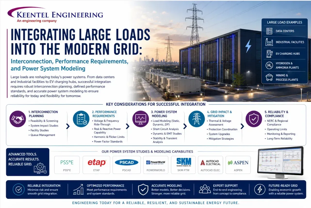
Large Load Interconnection and Power System Modeling for Data Centers, AI Facilities and Electrolyzers
May 16, 2026 | Blog
Large Loads, New Rules: Engineering Grid Reliability in the Age of Data Centers and AI
Introduction: A Fundamental Shift in Load Characteristics
The electricity grid has managed industrial loads for over a century. Steel mills, chemical plants, mines, and smelters have always demanded large blocks of power from transmission systems. But the large loads now connecting to the grid — AI training facilities, hyperscale data centers, cryptocurrency mining operations, advanced semiconductor fabrication plants, and green hydrogen electrolyzers — are categorically different from anything the industry has dealt with before.
The differences are not just in scale, although scale matters enormously. They lie in concentration, behavior, power electronics interfaces, load variability profiles, and the speed at which these facilities are being deployed. Existing interconnection frameworks, modeling tools, performance standards, and operational protocols were not designed for loads of this character. The result is a widening gap between what the grid needs to operate reliably and what current practices provide.
At Keentel Engineering, we track these developments closely. This brief draws on the most current technical research and industry practice to provide a comprehensive engineering perspective on what integrating large power-electronic loads actually requires — in terms of modeling, performance, and process.
What Makes Modern Large Loads Different
Grid engineers and planners are sometimes asked: we have had large industrial loads for decades — what is really new here? The answer is that several characteristics have converged simultaneously in a way that creates genuinely novel reliability challenges.
Size and Geographic Concentration
A major steel mill or aluminum smelter might draw two or three hundred megawatts. A modern hyperscale data center campus can exceed a gigawatt. More importantly, multiple such facilities are being sited in close proximity — sometimes in the same substation area or industrial park — creating load concentrations equivalent to entire cities in footprints measured in acres rather than square miles. The density of power demand in these areas has no historical precedent in transmission planning experience.
Highly Dynamic Load Profiles
Traditional large industrial loads — motors, furnaces, electrolytic processes — tend to draw relatively stable power with gradual ramp rates. Modern AI training facilities are fundamentally different. GPU compute clusters ramp up and down during training cycles, creating rapid swings in active power consumption that can occur on timescales of seconds. Cryptocurrency mining loads adjust aggressively based on profitability signals. These profiles introduce high-frequency variability that has the potential to excite oscillatory modes in power systems in ways that aggregated conventional load never did.
Engineering Insight Forced Oscillation Risk
A well-documented event involved a small generator oscillating at approximately four-second intervals. Despite modest individual magnitude, the oscillation excited a natural inter-area mode and produced hundreds of megawatts of power swings that propagated across the entire eastern interconnection from the southeastern United States to northern Manitoba. A large AI training facility exhibiting cyclic active power consumption at a similar frequency — but with far greater magnitude — represents a materially higher risk of the same phenomenon. Load-induced forced oscillation is an underappreciated reliability risk that must be addressed explicitly in interconnection studies.
Power Electronic Interfaces
Inverter-based generation has been the central modeling and stability challenge for the past decade. Large loads connected through power electronic interfaces — variable-frequency drives, rectifiers, switch-mode power supplies, uninterruptible power systems — present similar challenges from the load side. Protection systems designed to prevent damage to sensitive computing equipment can cause abrupt, coordinated disconnections of hundreds of megawatts. Phase-locked loops that lose synchronism can alter active power consumption in unpredictable ways. The control dynamics of these loads interact with the grid in ways that existing load models — developed for motors and heating elements — cannot represent.
Uncertainty in Load Growth Forecasts
Load growth across the grid had been essentially flat for two decades. Planners and economists had built careers around managing a largely static demand picture. The emergence of large power-electronic loads has broken this pattern abruptly. Forecasts for large load interconnection queues can vary by enormous margins — not due to poor forecasting methodology, but because the underlying development activity itself is rapid, uncertain, and difficult to observe from outside. Projects are announced, modified, relocated, or cancelled on short timescales. Planners are building transmission infrastructure against forecasts that carry unprecedented uncertainty.
The Modeling Challenge: Getting the Physics Right
Accurate power system modeling is the foundation of reliable interconnection. Before a large load facility connects to the transmission system, planners need models that accurately represent how that load will behave during normal operations and, critically, during disturbances. For modern large power-electronic loads, the modeling challenge is significant.
Why Legacy Load Models Fall Short
The dominant load modeling framework used across North American power systems is the composite load model — a sophisticated representation that captures motor loads, power electronics, discharge lighting, and other components typical of residential, commercial, and mixed industrial areas. The composite load model has been a major advance over earlier simplified approaches. But it was not designed to represent the specific characteristics of AI data centers, GPU clusters, or electrolyzers.
A composite load model cannot capture the cyclic active power variability of an AI training facility. It cannot represent the ride-through logic of a facility designed around protecting sensitive computing equipment rather than staying connected to the grid. It does not model the harmonic injection characteristics of large rectifier banks. It cannot represent the phase-jump tolerance thresholds of power-electronic front ends. New modeling frameworks are needed.
Positive Sequence vs. Electromagnetic Transient Modeling
Two fundamentally different simulation frameworks are used in power system studies, and understanding when each is appropriate is essential for correctly assessing large load impacts.
Positive sequence phasor-domain tools — the workhorses of transmission planning — operate in the sub-10 Hz frequency range and model the bulk power system at the level of buses, lines, and aggregated components. These tools are computationally efficient enough to model entire interconnections and are well suited for studying inter-area oscillations, transient stability, and voltage stability issues that affect large portions of the grid. When assessing the bulk system impact of a large load — its effect on voltage profiles across a region, its participation in frequency events — positive sequence modeling is the appropriate platform.
Electromagnetic transient tools model the system in three-phase detail, capturing fast dynamics associated with power electronic switching, phase-locked loop behavior, subsynchronous resonance, and converter-driven instabilities. EMT modeling is computationally intensive and is typically applied to a local portion of the system with an equivalenced representation of the broader network. For large loads with significant power electronics, EMT studies are often needed to identify local instabilities, harmonic interactions, and subsynchronous oscillation risks that positive sequence tools cannot capture.
Key Decision Principle Choosing the Right Tool
The choice between positive sequence and EMT modeling should be driven by the phenomena being studied, not by familiarity or computational preference. Positive sequence tools systematically miss fast-dynamics phenomena that can cause real stability problems near large power-electronic loads. The appropriate approach is to start with positive sequence analysis for bulk system impact assessment and to trigger EMT studies when screening criteria indicate elevated risk — based on facility size, system strength at the point of interconnection, proximity to other power-electronic equipment, and load profile characteristics.
Generic vs. OEM-Specific Models
For both positive sequence and EMT platforms, a distinction exists between generic library models and original equipment manufacturer-specific models. Generic models are white-box representations designed to capture the general behavior of a class of equipment — useful for planning studies where actual equipment vendors are not yet selected, and for training and exploratory analysis. OEM-specific models are black-box representations developed by equipment manufacturers to replicate the behavior of their specific products. They are generally more accurate for site-specific studies but are difficult to inspect, may have undisclosed limitations, and require coordination with the manufacturer for tuning and validation.
A critical engineering principle applies to both: more detailed modeling does not automatically mean better modeling. A complex EMT model with incorrect parameters or coding errors can produce misleading results that are worse than a well-calibrated positive sequence model. Model accuracy depends on the quality of development, parameterization, and validation — not on the sophistication of the platform.
Essential Model Characteristics for Large Load Facilities
Any dynamic model submitted for interconnection studies of a large power-electronic load facility should, at minimum, be capable of representing:
- Active power and frequency response — including any frequency-sensitive load reduction logic
- Reactive power capability and voltage control — including any on-site voltage regulation equipment
- Load profile variability — including cyclic ramp behavior during AI training or computing cycles
- Voltage ride-through logic — the thresholds and timing of load reduction or disconnection during voltage disturbances
- Ramp rate limitations — both normal operational ramps and post-disturbance recovery ramps
- Ride-through counter logic — including any multi-strike disconnection thresholds
- On-site generation behavior — if backup or co-located generation exists
- Mechanical load characteristics — for motor-driven processes within the facility
- Unbalanced voltage operation — for EMT models operating on per-phase voltages
- Pre-charge and startup behavior — if the model will be used for black-start or restoration studies
Model Validation: Closing the Loop Between Paper and Reality
A model that has not been validated against actual facility behavior is an educated guess. For large power-electronic loads — where behavior can be complex, non-linear, and sensitive to control settings unvalidated models represent a significant planning risk. Model validation requires:
- Parameter verification: Confirming that all model parameters match actual facility settings and equipment ratings, using OEM data sheets and commissioning records
- Dynamic event validation: Comparing model responses against recorded fault or disturbance data from digital fault recorders at the facility
- Continuous operating characteristic validation: Using phasor measurement unit data to compare steady-state and slowly-varying model behavior against observed performance
A structured model quality testing protocol should be applied before any model is accepted for use in planning or interconnection studies. Quality tests include: platform stability tests confirming the model initializes and runs without numerical artifacts; voltage and frequency ride-through tests confirming the model responds appropriately to disturbances; phase angle jump tests; and controlled load change tests confirming the model follows set-point changes without oscillatory or numerically unstable behavior.
Performance Requirements: What the Grid Needs from Large Loads
Model accuracy is necessary but not sufficient. Large load facilities must also be required to perform in specific ways during grid disturbances. Without clear performance requirements written into interconnection agreements, a facility may behave in ways that are rational from its own operational perspective but disruptive or dangerous from the grid's perspective.
Voltage Ride-Through: Two Perspectives in Conflict
A fundamental tension exists in how 'ride-through' is understood by grid operators versus by large load facility operators. From the grid perspective, voltage ride-through means that a facility remains electrically connected to the system during and after a disturbance — maintaining the post-contingency network configuration that planners designed for. From the facility perspective, ride-through means that internal processes continue without interruption regardless of grid conditions. These two definitions are not the same. An AI training facility can maintain internal computational continuity using on-site uninterruptible power systems while simultaneously disconnecting from the grid — providing 'ride-through' by its own definition but causing a large loss of load from the grid's perspective.
Grid performance requirements must be explicit that ride-through means remaining connected to the transmission system and restoring load according to specified timelines after disturbances clear — not merely maintaining internal operational continuity.
Reliability Alert: The bulk of computing equipment in modern data centers follows the ITIC (Information Technology Industry Council) curve for voltage tolerance — a standard developed to protect equipment from damage, not to maintain grid connectivity. ITIC does not constitute adequate grid ride-through requirements. Interconnection agreements must specify separate, grid-oriented ride-through curves.
Developing Site-Specific Ride-Through Curves
A single universal ride-through curve is not appropriate for all locations and system topologies. The appropriate curves for low-voltage and high-voltage ride-through at any given point of interconnection should be developed based on:
- Local fault clearing times — both normal clearing (protection operating correctly) and delayed clearing (backup protection scenarios)
- The most severe credible contingency events at or near the point of interconnection
- Normal voltage operating ranges at the facility's point of interconnection
- Whether automated post-contingency actions are used to restore voltages within acceptable ranges
A review of international practice reveals significant variability in ride-through requirements across jurisdictions — reflecting the different fault clearing times, protection philosophies, and system topologies in each system. This variability reinforces that jurisdiction-specific and site-specific curve development is the appropriate approach, informed by — but not copied from — requirements developed for other systems.
Multi-Disturbance Ride-Through: The Three-Strikes Problem
Several large load facilities have implemented 'three-strikes' or similar counter-based disconnection logic: after a specified number of voltage disturbances within a defined time window, the facility disconnects. This logic makes sense from an equipment protection perspective — repeated voltage disturbances can indicate an unstable grid condition that poses risk to sensitive equipment. But from a reliability perspective, the consequences can be severe.
A double-circuit transmission contingency — a tower failure taking two parallel lines simultaneously — followed by unsuccessful automatic reclosure attempts on both lines is a routine, designed-for event in transmission planning. Under many three-strikes implementations, this single normal clearing contingency would trigger facility disconnection. If multiple large load facilities sharing a transmission corridor all implement similar logic, a single design contingency could remove gigawatts of load simultaneously, triggering frequency excursions, voltage instability, and cascading outcomes that planners did not design for.
The engineering recommendation is clear: where technically feasible, counter-based disconnection logic should be disabled. Where it cannot be disabled, the parameters must be explicitly coordinated with the system operator's normal and emergency operating procedures, ensuring that designed-for contingency sequences — including unsuccessful reclosures — do not trigger disconnection.
Active Power Recovery After Faults
Ride-through requirements must address not only whether a facility remains connected during a disturbance but how it recovers load afterward. If a large load reduces its consumption during a fault to facilitate ride-through — a legitimate and often necessary approach — it must restore that load in a controlled, coordinated manner to prevent post-fault stability problems.
The appropriate active power recovery rate depends on the strength of the system at the point of interconnection. In electrically strong locations, restoration of 90% of pre-fault load within one second of voltage recovery to 90% of nominal is achievable without system instability. In weaker systems, more gradual recovery over several seconds may be necessary to avoid voltage collapse during the post-fault restoration period. Performance requirements should specify recovery rates appropriate to system strength, with interconnection studies confirming that the specified rates do not introduce secondary instabilities.
Ramp Rate Control and Area Control Error
The active power variability of large power-electronic loads directly stresses the area control error (ACE) management of balancing authorities. Automatic generation control was designed to manage the gradual, predictable ramp rates of conventional loads and the scheduled dispatch of generation. Second-to-second or minute-to-minute swings of tens or hundreds of megawatts from large loads operating outside coordinated frameworks can exhaust regulation capacity rapidly.
Ramp rate requirements for large loads should be established through analysis of the balancing authority's existing regulation capacity and the cumulative impact of planned large load additions. Where individual facility ramp rates cannot be technically limited without disrupting operations, additional regulation procurement may be necessary. The key principle is that the cumulative variability of large loads must be within the system's demonstrated regulation capability, or that capability must be expanded to accommodate the new loads.
High-Frequency Cycling and Torsional Interaction
The high-frequency component of large load active power variability — cycling at frequencies of one to tens of hertz rather than the one-to-several-second low-frequency cycles associated with training workloads — poses a specific risk to conventional generating units located electrically close to the load facility. Thermal generating units have shaft systems with natural torsional modes in the one to fifty hertz range. If load-driven power oscillations excite these modes, the resulting cyclic shaft torques can cause fatigue damage.
Generator manufacturers specify shaft damage criteria in terms of shaft torque magnitude versus cycle count. Operating in the 'continuous' region — where oscillations are small enough to accumulate indefinitely without damage — is acceptable. Operation at higher torque levels can cause measurable damage within thousands of cycles — which at frequencies of several hertz can occur within minutes. This risk must be evaluated explicitly when citing large power-electronic load facilities near generating stations, with site-specific torsional interaction studies conducted where risk screening indicates potential concern.
Monitoring Requirements
Performance requirements are only enforceable if facility behavior can be observed and measured at sufficient resolution. Monitoring equipment installed at large load facilities should be capable of both streaming real-time data to the system operator and recording high-fidelity event data for post-disturbance analysis. A minimum sampling rate of 100 hertz is recommended to capture the phenomena relevant to large load interconnection performance — including high-frequency active power cycling and fast voltage transients. Recordings should be maintained for a minimum of 20 days to ensure that data from any significant system event is available for analysis.
Interconnection: A Critical but Double-Edged Asset
Even the best technical requirements are ineffective without a well-designed interconnection process to implement them. The generation interconnection process in North America has been through a multi-decade evolution — from ad hoc utility-by-utility procedures to standardized FERC-regulated frameworks — driven by the reliability problems that emerged when that process could not keep pace with the scale and speed of new generation development. Large load interconnection is at an earlier stage of the same evolution.
What a Baseline Large Load Interconnection Process Should Include
A rigorous large load interconnection process should encompass the following phases and milestones:
- Pre-application readiness review: Verification of site control, financial commitment, and completeness of technical data packages before formal application is accepted. This is the viability filter that prevents speculative applications from consuming limited study resources.
- Application package with modeling and performance data: Submission of dynamic models (positive sequence and EMT as appropriate), facility specifications, load profile data, and preliminary performance capability documentation at the time of application.
- Tiered study process: Tier 1 RMS-based power flow and dynamic stability studies for all applicants; screening analysis to identify facilities requiring detailed EMT studies based on size, system strength, load profile characteristics, and proximity to sensitive equipment.
- EMT study execution where triggered: Subsynchronous oscillation studies, control stability analysis, harmonic and power quality assessment, and torsional interaction screening for facilities that meet EMT study trigger criteria.
- Interconnection agreement with enforceable performance requirements: Ride-through curves, ramp rate limits, monitoring requirements, and compliance testing obligations incorporated as binding interconnection agreement terms.
- Construction and commissioning oversight: Verification that as-built facilities match studied configurations, with commissioning testing to confirm performance against requirements.
- Post-interconnection monitoring and compliance: Ongoing monitoring against requirements, with mechanisms for review and remediation if behavior does not conform to studied assumptions.
Coordination Between Transmission Entities and ISO/RTOs
A specific complexity of modern large load interconnection is that large facilities — particularly those co-located with or supported by generation resources — simultaneously engage multiple regulatory entities. The transmission utility is responsible for local interconnection studies and facilities. The ISO or RTO is responsible for generation interconnection (if co-located generation is involved), transmission planning, and market participation. When a facility involves both load interconnection and co-located or nearby generation, these two processes must be coordinated to ensure that studies are consistent, requirements are compatible, and neither process creates gaps in reliability assessment.
The emerging policy landscape is creating new frameworks to manage this complexity — including new service categories for co-located generation and load, dedicated large load interconnection processes within ISO/RTO tariffs, and high-impact large load assessment procedures. These frameworks are still developing rapidly. The engineering principle that must be maintained throughout this evolution is that baseline technical requirements — modeling, performance, and monitoring — must be consistently applied regardless of which regulatory entity has primary jurisdiction over a given interconnection.
Lessons from Generation Interconnection Reform
The history of generation interconnection reform provides a useful template. Over roughly two decades, the North American generation interconnection process evolved from fragmented, utility-specific procedures to standardized frameworks with transparent queue management, defined study milestones, commercial readiness requirements, and enforceable interconnection agreements. This evolution was driven by the reliability problems and market inefficiencies that emerged when the process could not keep pace with the scale of renewable energy development. Large load interconnection is now in an analogous early period — and the engineering community has the benefit of knowing where the generation interconnection process eventually needed to go.
Key lessons applicable to large load interconnection include: the importance of commercial readiness filters at the application stage to weed out speculative projects; the value of standardized study processes that enable consistent treatment of similar applicants; the necessity of enforceable performance requirements incorporated into interconnection agreements rather than left as voluntary guidelines; and the need for ongoing monitoring and compliance infrastructure to ensure that as-built and operating facilities continue to meet the requirements they were studied to.
Demand-Side Flexibility: A Depth Reducer, Not a Duration Reducer
A specific sensitivity test fixed demand-side flexibility (DSF) capacity in one portfolio at 2030 levels and held it constant through 2040, rather than allowing it to grow. The results were nuanced:
- Overall LOLE change was modest — DSF growth did not dramatically change the number of hours of loss of load
- However, within stress events, expected unserved energy increased significantly when DSF was constrained
The practical interpretation: demand-side flexibility is most valuable not for preventing outages entirely, but for limiting the severity of outages that do occur. It reduces the depth of shortfall events — the total amount of energy not served during a crisis — rather than eliminating the events themselves.
For engineering teams designing demand response programs, this finding suggests that valuation frameworks focused purely on peak demand reduction may underestimate DSF's contribution to system resilience. Metrics that capture unserved energy depth, not just hours of outage, are needed.
Conclusions: Engineering the Grid for the Large Load Era
The integration of large power-electronic loads at the scale now being observed represents one of the most significant reliability engineering challenges the grid has faced. It combines the modeling complexity of inverter-based resources with the scale and speed of development that overwhelmed the generation interconnection process a decade ago — and it is occurring simultaneously with the integration of large amounts of inverter-based generation, making the overall system stability picture more complex than either challenge alone.
Keentel Engineering's perspective is that the tools, techniques, and frameworks needed to manage this challenge exist or are being developed. The gaps are primarily in implementation — in applying rigorous modeling and performance requirements consistently, in building interconnection processes capable of handling the volume and complexity of applications, and in investing in the monitoring infrastructure needed to close the feedback loop between studied and actual behavior.
The large load era is not a reliability crisis waiting to happen. It is an engineering challenge that can be met with the systematic application of good engineering practice: accurate models, clear requirements, structured processes, and continuous learning from operating experience.
CASE STUDIES — KEENTEL ENGINEERING
Large Load Integration in Practice: Three Keentel Engineering Engagements
The following case studies describe how Keentel Engineering has applied the technical principles discussed in this brief to real-world engineering challenges across modeling, performance assessment, and interconnection process design.
Dynamic Model Development and Validation for a 600 MW AI Data Center Campus
Creating and validating positive sequence and EMT models for a hyperscale AI training facility in a high-penetration IBR region
Background
A hyperscale technology company engaged Keentel Engineering to develop and validate dynamic power system models for a 600 MW AI training campus interconnecting at 345 kV. The facility comprised three phases of GPU compute clusters, each with a target installed GPU density of approximately 200 MW, with all three phases ultimately interconnected at a single high-voltage substation via dedicated step-up transformers.
The interconnection study region was characterized by high penetration of inverter-based wind generation and existing concerns about subsynchronous oscillation risk. The transmission utility required both positive sequence and EMT models as conditions of the interconnection application. The technology company had not previously developed grid-connected power system models and had limited experience engaging with transmission interconnection technical processes.
Technical Challenge
The facility's GPU compute clusters were procured from multiple OEMs, using different rectifier topologies and power electronics platforms. Each OEM provided black-box dynamic models, but the models were developed for different simulation platforms, had inconsistent documentation, and had not previously been validated against field data at any operating facility. Three specific technical challenges required resolution:
- Platform incompatibility: Two of the three OEM models were available only in platforms not used by the transmission utility for interconnection studies. Conversion or re-development was required.
- Active power cycling characteristics: Preliminary load data from a similar operating facility showed active power cycling with a dominant frequency of approximately 0.3 Hz during training cycles — directly coinciding with a known inter-area oscillatory mode in the regional interconnection.
- Multi-strike logic: The facility's internal protection systems included a five-strike counter that would disconnect the facility from the grid after five voltage dips within 30 seconds. Analysis showed this could be triggered by a normal delayed-clearing fault scenario in the interconnection area.
Keentel Engineering Approach
Phase 1: Model Development
Keentel Engineering worked with each OEM to obtain functional block diagrams and parameter definitions for their respective models. Where OEM models were available only in incompatible platforms, Keentel Engineering developed equivalent positive sequence models using the functional block diagrams as specifications, implementing them in the transmission utility's preferred simulation platform. EMT models were developed for the two GPU cluster designs with the most significant power electronic interaction risk, using a combination of OEM-provided switching-level models equivalenced to average models for the interconnection study application.
Phase 2: Model Quality Testing
All developed models underwent the full model quality test suite before submission for interconnection study use. Two models initially failed the ride-through response test — their simulated response to voltage dips did not replicate the protective relay settings documented in the facility's protection coordination study. After parameter correction in coordination with the OEMs, all models passed all quality tests.
Phase 3: Forced Oscillation Assessment
Keentel Engineering conducted a detailed forced oscillation assessment using the validated positive sequence model. The analysis confirmed that the facility's 0.3 Hz active power cycling would inject energy into the regional inter-area mode. Simulations showed oscillation amplitudes building to approximately 180 MW at the regional interchange points over a 60-second period — below thresholds for immediate system instability but representing a material and growing reliability concern.
Keentel Engineering worked with the technology company's operations team to evaluate four mitigation approaches: job scheduling smoothing, GPU power limits, rack-level battery buffering, and facility-level BESS A combination of rack-level battery buffering and job scheduling smoothing was selected as the primary mitigation, achieving approximately 75% reduction in cycling amplitude at the dominant frequency in bench testing.
Phase 4: Multi-Strike Logic Coordination
The five-strike counter was reconfigured in coordination with the facility protection engineer and the transmission utility to require 12 voltage dips within 60 seconds before disconnecting — a threshold that could not be reached by any designed-for contingency sequence in the interconnection area, while still providing equipment protection against sustained multi-fault scenarios.
Outcomes
| Facility Capacity | 600 MW (3 × 200 MW phases) |
|---|---|
| Models Developed | 3 positive sequence models, 2 EMT models |
| Quality Test Results | All models passed after parameter corrections — 2 models required parameter revision |
| Forced Oscillation Mitigation | 75% reduction in dominant cycling amplitude achieved with combined rack BESS + scheduling smoothing |
| Multi-Strike Reconfiguration | Counter threshold revised from 5 strikes/30s to 12 strikes/60s; all designed-for contingencies cleared within new threshold |
| Interconnection Outcome | Models accepted by transmission utility; interconnection agreement executed with monitoring and performance requirements |
Post-energization monitoring data collected in the first six months of operation showed close agreement between modeled and observed facility behavior during two minor voltage disturbances in the interconnection area, providing validation of the model quality across two of the three OEM equipment types. The third OEM equipment type has not yet experienced a disturbance of sufficient magnitude for validation and remains on a schedule for parameter verification based on PMU continuous data.
Large Load Interconnection Process Design for a Regional Transmission Utility
Developing a standardized, technically rigorous interconnection framework for an emerging large load queue of over 8 GW
Background
A regional transmission-owning utility retained Keentel Engineering to design a comprehensive large load interconnection process framework. The utility had experienced a rapid influx of large load interconnection applications — primarily data centers and AI computing facilities — that had overwhelmed its existing interconnection processes. The existing process had been designed around conventional industrial load interconnections of tens of megawatts and did not include requirements for dynamic models, performance specifications, or EMT studies
Within 18 months, the utility had accumulated over 8 GW of large load interconnection applications, with individual project sizes ranging from 80 MW to 1.1 GW. Several early applications had been approved and were under construction using conventional process steps. Concerns were emerging about whether the reliability impacts of these facilities had been adequately studied.
Technical Challenge
The utility faced three distinct challenges simultaneously. First, retrospective assessment of approved projects: How to evaluate whether already-approved facilities posed reliability risks that had not been captured in their original interconnection studies. Second, prospective process design: How to design a new interconnection process framework that addressed the full range of technical risks posed by modern large power-electronic loads. Third, queue management: How to restructure its interconnection queue to prioritize projects with demonstrated commercial readiness while ensuring that speculative applications did not consume limited study resources.
Keentel Engineering Approach
Component 1: Retrospective Assessment Framework
Keentel Engineering developed a tiered retrospective assessment protocol for the 14 already-approved projects in construction or early operation. Projects were screened against risk criteria including: facility capacity above 200 MW; location in areas with existing subsynchronous oscillation concerns; load profiles with documented high-frequency cycling; and interconnection at 138 kV or below. Six projects were classified as requiring detailed dynamic assessment. Keentel Engineering conducted positive sequence dynamic studies for all six and EMT studies for three that met EMT trigger criteria. Two projects required mitigation measures — one required revised ride-through settings confirmed through model simulation; the other required installation of harmonic filters not included in the original interconnection design.
Component 2: New Process Framework Design
The new interconnection process framework established the following key elements:
- Commercial readiness filter: All new applications must demonstrate site control, letter of credit, and preliminary equipment procurement documentation before entering the study queue. Applications without commercial readiness evidence are placed in a pre-queue status.
- Technical data package requirements: Dynamic model submission (positive sequence and EMT where applicable), load profile documentation, protection settings documentation, and preliminary performance capability assessment required at application.
- Tiered study process: Tier 1 RMS studies for all applicants; EMT study trigger criteria applied based on six screening factors; Tier 2 detailed EMT studies for triggered projects.
- Standardized performance requirements: Ride-through curves developed for four system zones reflecting different fault clearing times and system strengths; ramp rate requirements established based on balancing authority regulation capacity analysis; monitoring requirements standardized across all new large load interconnections.
- Model quality testing: Mandatory quality test results required before models are accepted for Tier 1 or Tier 2 studies; OEM models must pass quality tests in the utility's simulation platform.
Component 3: Queue Restructuring
The existing interconnection queue was restructured using a cluster study approach, grouping applications by substation area and applying shared network upgrade cost allocation across clusters. Commercial readiness milestones were introduced at 90-day intervals; applications missing consecutive milestones were withdrawn from the queue, creating capacity for new applications with stronger development progress.
Outcomes
| Retrospective Review Scope | 14 approved projects, 6 detailed assessments, 3 EMT studies |
|---|---|
| Retrospective Findings | 2 projects required mitigation measures identified through dynamic assessment |
| New Framework Elements | Commercial readiness filter, 6-factor EMT screening criteria, 4-zone ride-through curves, standardized monitoring requirements |
| Queue Restructuring | 31% of queue applications (by MW) withdrew voluntarily after commercial readiness milestones introduced |
| Study Timeline Impact | Average interconnection study completion time reduced by 28% in first year of new framework implementation |
| Ongoing Capacity | Study team capacity now covers queue of 6.2 GW active applications with standardized process |
The retrospective assessment identified reliability risks in two projects that had been approved without dynamic modeling — risks that would have been identified and mitigated earlier under the new process framework. Both projects have since completed required mitigation measures and are operating within their interconnection performance requirements. The new framework has been shared with several neighboring transmission utilities as a reference model for their own large load process development.
Active Power Recovery and Ride-Through Compliance Assessment for a Green Hydrogen Electrolyzer Facility
Designing and verifying ride-through performance requirements for a 400 MW electrolysis facility in a weak grid interconnection area
Background
A green hydrogen developer engaged Keentel Engineering to perform a comprehensive ride-through performance assessment for a 400 MW electrolyzer facility interconnecting at 230 kV in a system area characterized by relatively low short-circuit ratios and significant penetration of inverter-based renewable generation. The project was the first large electrolyzer facility to seek interconnection in the utility's service territory, and no established interconnection requirements existed for this technology type.
The electrolyzer technology used proton exchange membrane (PEM) electrolysis — a power-electronic-interfaced process with operating characteristics significantly different from either conventional industrial loads or the alkaline electrolysis technology that had been studied in prior literature. The utility required Keentel Engineering to characterize the facility's behavior, develop appropriate performance requirements, verify that the proposed facility design could meet those requirements, and identify any mitigation measures needed.
Technical Challenge
The electrolyzer facility presented several specific technical challenges that were not addressed by existing interconnection standards or prior literature:
- Weak grid interconnection: Short-circuit ratio at the proposed point of interconnection was 2.8 — below the threshold at which many conventional ride-through requirements are designed to be achievable, and in a range where PLL stability under voltage disturbances is a documented concern for power-electronic devices.
- No OEM EMT model: The PEM electrolyzer OEM had not previously developed an EMT model for their equipment. A positive sequence model existed but had not been validated against field measurements from any operating facility.
- Hydrogen process continuity constraints: The developer required that the electrolyzer ride-through approach minimize disruption to the hydrogen production process. Abrupt full disconnection and reconnection cycles cause thermal and membrane stress that affects electrolyzer life. The ride-through approach needed to balance grid requirements with equipment protection considerations.
- Active power recovery in a weak system: The weak grid interconnection meant that rapid restoration of full electrolyzer load after a fault could itself trigger voltage instability — the load restoration acting as a second disturbance on an already recovering system.
Keentel Engineering Approach
Phase 1: Characterization Studies
Keentel Engineering conducted a detailed characterization of the PEM electrolyzer's electrical behavior through a combination of OEM technical documentation review, laboratory test data analysis, and engineering analysis of the power electronic front end. Key characteristics determined included: minimum voltage below which partial rather than full load reduction occurs; maximum PLL phase jump tolerance under laboratory conditions; natural ramp-down and ramp-up rates driven by the electrolysis process thermal dynamics; and harmonic current injection characteristics at the fundamental and key harmonic frequencies.
Phase 2: Site-Specific Ride-Through Curve Development
Keentel Engineering developed site-specific ride-through curves for the 230 kV interconnection point based on fault simulation studies for the interconnection area. Key parameters determined through simulation included: voltage at the facility terminals during a three-phase fault with normal clearing (shortest expected duration); voltage during a single-line-to-ground fault with delayed clearing (worst-case sustained voltage depression); and post-fault voltage recovery profile for the credible contingency cases. The resulting ride-through curves were specific to the system characteristics at this interconnection point, with a low-voltage ride-through requirement that was less stringent than standard IBR requirements in recognition of the weak grid context, combined with a requirement for partial load reduction during the fault to support voltage recovery.
Phase 3: Active Power Recovery Protocol
The active power recovery protocol was developed to address both grid stability and electrolyzer process constraints. The protocol specifies a four-stage recovery sequence following fault clearing: Stage 1 (0–2 seconds post-clearing): Maintain load at the partial level held during the fault; do not begin recovery until terminal voltage reaches 90% of nominal. Stage 2 (2–10 seconds): Ramp load recovery at a rate consistent with the system strength at the point of interconnection — slower than IBR standards recommend for strong system locations. Stage 3 (10–60 seconds): Continue controlled ramp toward pre-fault load level, subject to real-time voltage monitoring that can pause recovery if terminal voltage falls below a secondary threshold. Stage 4: Full load restoration confirmed when terminal voltage has been maintained above 95% of nominal for 30 consecutive seconds.
The recovery protocol was tested in simulation using the positive sequence model across all credible contingency scenarios for the interconnection area. In no scenario did the controlled recovery cause secondary voltage instability. The facility's modeled voltage profile remained within the normal operating range throughout all recovery simulations.
Phase 4: EMT Model Development
Working with the OEM, Keentel Engineering developed an EMT model of the PEM electrolyzer facility from functional specifications and laboratory data. The model was parameterized using the characterization data from Phase 1 and validated against available laboratory test data. Simulation studies using the EMT model confirmed acceptable PLL stability for the modeled fault scenarios at the facility's short-circuit ratio, with a specific finding that PLL performance degraded materially for faults causing terminal voltage below 0.4 per unit — informing a recommendation for enhanced PLL tuning as a condition of interconnection commissioning.
Outcomes
| Facility Type | 400 MW PEM electrolyzer, 230 kV interconnection |
|---|---|
| Short-Circuit Ratio | 2.8 (weak grid; below standard IBR ride-through assumption) |
| Ride-Through Approach | Partial load reduction to 40% during fault; staged 60-second recovery protocol post-fault |
| Active Power Recovery | Four-stage protocol; voltage-gated with pause capability; validated across all credible contingencies |
| PLL Finding | Standard PLL tuning marginally stable for faults below 0.4 pu voltage; enhanced tuning required as commissioning condition |
| Hydrogen Process Impact | Staged recovery approach reduced membrane thermal cycling by approximately 60% vs. abrupt disconnect/reconnect |
| Interconnection Status | Performance requirements accepted; interconnection agreement executed; commissioning testing scheduled |
The engagement established a precedent for PEM electrolyzer interconnection performance requirements in the utility's service territory and has informed subsequent electrolyzer interconnection applications by other developers. The staged active power recovery protocol has been recognized by the utility's planning team as a model for active power recovery requirement design in weak grid interconnection areas — applicable to both large load and inverter-based generator interconnections in similar system strength contexts.
TECHNICAL FAQ — 20 QUESTIONS ANSWERED BY KEENTEL ENGINEERING
Integrating Large Loads: Technical FAQ for Grid Engineers and Planners
Keentel Engineering's transmission planning, interconnection, and power systems engineering teams address the twenty most frequently asked technical questions on large load integration.
Q1. What makes modern large power-electronic loads fundamentally different from legacy large industrial loads when it comes to interconnection studies?
A: Four characteristics distinguish modern large loads from historical industrial facilities: (1) Size and concentration — individual facilities approaching or exceeding a gigawatt, clustered in dense geographic areas, creating load density with no historical precedent in transmission planning. (2) Dynamic load profiles — rapid active power swings driven by AI training cycles, cryptocurrency mining algorithms, or electrolysis process control, operating on timescales of seconds rather than minutes. (3) Power electronic interfaces — rectifiers, switch-mode power supplies, and variable-frequency drives that can disconnect abruptly based on equipment protection logic, interact with PLL-based synchronization, and inject harmonics in ways that conventional motors and resistive loads do not. (4) Multi-strike disconnection logic — counter-based protection designed for equipment safety that can cause coordinated, simultaneous disconnection of multiple large facilities during normal power system events. Interconnection studies must explicitly address all four characteristics rather than treating these facilities as scaled-up versions of conventional loads.
Q2. When should electromagnetic transient (EMT) studies be required for large load interconnections, and what specific risks do they identify that positive sequence studies cannot?
cannot?
A: EMT studies should be triggered when a large load facility meets one or more screening criteria: facility capacity exceeding a threshold (typically 100–200 MW depending on system strength at the point of interconnection); location in areas of low short-circuit ratio indicating weak system; proximity to other large power-electronic equipment including inverter-based generation; load profiles exhibiting significant high-frequency cyclic behavior; or interconnection at or below 230 kV where the local system is more susceptible to fast transients. EMT studies can identify phenomena that positive sequence tools systematically miss: phase-locked loop instability and synchronization loss; subsynchronous oscillation risks between large loads and nearby generators; high-frequency resonance between load power electronics and local network impedances; harmonic amplification due to network-load resonance; and converter-driven instabilities that develop on sub-cycle timescales. These phenomena are local in nature and require the detailed three-phase, fast-timestep modeling that only EMT platforms provide.
Q3. What are the minimum data requirements that should be collected from a large load facility before a valid dynamic model can be developed and validated?
A: A complete data package for large load dynamic model development requires four categories of information. Electrical system data: cable parameters, transformer ratings and impedances, voltage regulator specifications, reactive compensation device ratings, harmonic filter characteristics, and point-of-interconnection equipment ratings. Control and protection settings: ride-through thresholds and timers (both voltage and frequency), PLL parameters and phase-jump tolerances, ramp rate limiters, multi-strike counter logic, automatic voltage regulator settings if present, and any frequency-responsive load control. Load profile data: representative active and reactive power time series including both normal operation and high-variability periods such as AI training cycles. Event and measurement data: digital fault recorder captures from previous disturbances at or near the facility, and continuous PMU data covering a range of normal operating conditions. Without these four categories, model validation cannot be performed and model accuracy cannot be assured.
Q4. How should model validation be structured for a large load facility, and what constitutes acceptable agreement between model and measured response?
A: Model validation should be structured in two sequential phases. Phase 1 — Parameter verification: All model parameters are checked against OEM documentation, equipment nameplates, and commissioning records. Discrepancies are resolved before dynamic simulations begin. Phase 2 — Response validation: The model is simulated through events for which measured facility data exists — ideally voltage disturbances captured by DFRs, and continuous operating data from PMUs. Model outputs are compared against measurements for active power, reactive power, terminal voltage, and any available current measurements. Acceptable agreement is typically defined as: transient peak error within ±10% of peak response magnitude; time-to-peak error within one to two cycles; and steady-state error within ±5% following the initial transient. Where discrepancies exceed these thresholds, model parameters should be refined and the simulation repeated. Model quality tests — platform stability, ride-through response, phase jump, and controlled load change — must be passed before the model is accepted for planning study use.
Q5. What is the technical basis for requiring large loads to meet voltage ride-through requirements similar to those applied to inverter-based generators?
A: The technical basis is behavioral equivalence. Both inverter-based generators and large power-electronic loads interact with the grid through power electronic converters that are controlled by software logic rather than driven by physical inertia. Both can disconnect rapidly and in large blocks based on threshold logic embedded in their control systems. Both operate with phase-locked loops whose loss of synchronism can cause abrupt changes in active power exchange. The grid does not distinguish between a megawatt of generation that trips offline and a megawatt of load that disconnects — both alter the power balance and can trigger cascading consequences. Applying equivalent ride-through requirements to both resource types creates consistency in the post-contingency behavior that planners can design and study for reliably.
Q6. How should ride-through curves be developed for a specific point of interconnection rather than applied as a generic standard?
A: Site-specific ride-through curve development requires four inputs. First, fault clearing time analysis: The fastest and slowest fault clearing times expected at or near the point of interconnection under both normal clearing (primary protection) and delayed clearing (backup protection) scenarios. This defines the minimum voltage dip duration the facility must ride through. Second, worst-case voltage depression characterization: Power flow and dynamic simulations of the most severe credible contingency events at the site, determining the depth of voltage depression at the load terminals. Third, high-voltage contingency characterization: Post-fault voltage recovery and potential temporary overvoltage magnitudes, which define the high-voltage ride-through requirements. Fourth, voltage operating range: The normal and emergency voltage operating ranges at the point of interconnection, which define the starting point for ride-through assessment. These inputs together define the minimum voltage versus time envelope that the facility must ride through without disconnecting from the system.
Q7. What technical approaches can large load facilities use to achieve voltage ride-through while protecting sensitive computing or process equipment?
A: Several engineering approaches enable grid ride-through compliance while maintaining internal equipment protection. Dynamic UPS with extended hold-up time: Uninterruptible power systems sized and programmed to supply facility loads through the ride-through event duration without drawing reduced power from the grid, allowing the facility to maintain grid connection even as internal voltage sags. Active power reduction during disturbances: Reducing facility active power consumption during the voltage disturbance reduces facility terminal current, which can help support local voltage recovery. This is an active contribution to grid stability, not merely a passive ride-through strategy. Fast reactive power injection: On-site STATCOM or capacitor banks that inject reactive power during voltage disturbances, supporting local voltage and assisting the facility's own ride-through. Load management and staged recovery: Implementing controlled, staged reconnection of facility internal loads after a disturbance, consistent with active power recovery requirements in the interconnection agreement. The large load community has been actively developing these approaches, recognizing the operational benefits of being 'good grid citizens' in addition to meeting regulatory requirements.
Q8. How should counter-based or multi-strike disconnection logic be handled in interconnection performance requirements?
A: Counter-based disconnection logic should be addressed in three steps. First, determine whether the logic can be disabled entirely. Many modern facility protection systems allow this capability to be turned off through configuration changes. If disabling is technically feasible, this is the preferred approach, and disabling should be a condition of the interconnection agreement. Second, if the logic cannot be disabled, the counter parameters must be explicitly coordinated with the system operator's normal and emergency operating procedures. Specifically, the counter thresholds must not be triggered by any designed-for contingency sequence in the local interconnection area, including double-circuit contingencies with unsuccessful automatic reclosure. Third, counter parameters must be documented in the interconnection agreement and subject to review if system operating procedures change. The analysis must consider multi-facility scenarios — if multiple large loads in a corridor share similar counter logic, a single contingency sequence could trigger simultaneous disconnection of all facilities.
Q9. What is the risk of low-frequency active power cycling from AI training workloads, and how should it be assessed and mitigated?
A: Low-frequency active power cycling — with periods of approximately two to ten seconds corresponding to AI training batch processing cycles — poses the risk of exciting inter-area oscillatory modes of the power system. Most large interconnections have natural lightly damped oscillatory modes in the 0.1 to 0.5 Hz frequency range (two to ten second periods). If a large load's cyclic power variations are at or near these frequencies, they can inject energy into these modes, causing their amplitude to grow — a forced oscillation phenomenon. The consequences can propagate across very large geographic areas. Assessment requires: identifying the natural oscillatory modes of the relevant interconnection portion using small-signal stability analysis; comparing load cycling frequency ranges against these modes; and simulating the forced oscillation response using both positive sequence and EMT tools as appropriate. Mitigation options include: software smoothing of compute job scheduling to reduce the amplitude of cyclic variations; GPU computational limits that reduce peak-to-trough power swings; rack-level and facility-level battery energy storage to buffer output variability; and hardware-based power management that desynchronizes load cycles across GPU clusters.
Q10. How should high-frequency active power cycling — at frequencies above one hertz — be assessed for torsional interaction risk with nearby generating units?
A: Torsional interaction assessment for high-frequency load cycling requires three steps. First, identify generating units within the electrically relevant vicinity of the load facility — typically those within a few electrical buses or with high electrical coupling to the load connection point. Second, obtain torsional natural frequency data and shaft damage curves from the unit manufacturers. Damage curves express allowable shaft torque as a function of number of cycles at that torque level; the curves have a continuous region below which damage accumulation is negligible. Third, simulate the load cycling scenarios — sweeping across the relevant frequency range at the expected oscillation magnitudes — to determine the shaft torque response of each nearby unit. If the resulting shaft torques are within the continuous region of the damage curve at all relevant frequencies and magnitudes, torsional risk is acceptable. If shaft torques exceed the continuous region at any scenario combination, mitigations are required — either reducing load cycling magnitude, installing frequency-selective damping controls, or restricting the facility's operation during periods when nearby generators are susceptible.
Q11. What aggregation approach is appropriate when modeling a data center with hundreds or thousands of individual computing loads?
A: Aggregation for large load dynamic modeling follows principles similar to those established for wind and solar collector system aggregation, adapted for the characteristics of computing loads. The key principle is that aggregation should preserve the behaviors most relevant to the study at hand while reducing computational burden. For positive sequence studies, computing loads within a facility can typically be aggregated to one or a few equivalent loads at the facility's high-voltage bus, with aggregate parameters capturing the composite active and reactive power, ride-through characteristics, and ramp rate behavior. For EMT studies, the appropriate aggregation level depends on what phenomena are being studied: for subsynchronous oscillation and torsional interaction studies, the aggregate at the high-voltage bus is typically sufficient; for harmonic studies, the aggregate must preserve the harmonic current injection characteristics of the rectifier loads. Geographic concentration — the fact that all computing loads are within a single building or campus — means that collector system impedance effects are typically small compared to the transmission system, and fine-grained disaggregation provides little additional accuracy for transmission-level studies.
Q12. What monitoring equipment should be required at large load interconnections, and what are the key specifications?
A: Monitoring requirements for large load interconnections should include both real-time streaming capability for operational situational awareness and event recording capability for post-disturbance analysis and model validation. For real-time streaming: PMU-class devices providing voltage phasors, current phasors, active power, and reactive power at the high-voltage point of interconnection at a minimum rate of 30–60 frames per second, streaming to the system operator's control center or data aggregator. For event recording: High-resolution digital fault recorders capturing voltage and current waveforms at a minimum sample rate of 100 Hz — and preferably 256 Hz or higher for high-frequency phenomena — at the facility's high-voltage bus and, where practically feasible, at representative internal distribution buses. Recording triggers should capture all disturbances exceeding defined thresholds, with records maintained for a minimum of 20 days consistent with established standards for protection and monitoring devices. Data from both streaming and recording systems should be accessible to the system operator and available for use in model validation activities.
Q13. How should ramp rate requirements for large loads be quantified, and what are the interconnection study steps needed to establish appropriate limits?
A: Ramp rate requirement development is a system-specific analysis that must account for the balancing authority's current regulation capacity and the incremental impact of planned large load additions. The analysis has three steps. Step 1: Characterize the facility's unconstrained ramp profile. This requires actual load data where available, or engineering estimates based on the facility's operational characteristics — compute batch sizes, training cycle durations, and demand management software. For facilities not yet built, sensitivity analysis across plausible ramp profile envelopes is needed. Step 2: Simulate the cumulative impact of the facility's ramps on the balancing authority's area control error. This simulation should use the balancing authority's actual ACE data from representative historical periods, overlaying the additional variability from the new facility and any other large loads in the queue. Step 3: Compare the modeled ACE impact against the balancing authority's current regulation service capacity and automatic generation control capability. Where the analysis indicates that regulation capacity would be exhausted — leading to ACE exceedances — one or both of two actions are required: procurement of additional regulation service, or imposition of ramp rate limits on the facility as an interconnection requirement. The appropriate balance between these options is a system-specific judgment that should involve the balancing authority, the transmission planner, and the facility.
Q14. What is the significance of phase-locked loop behavior in large power-electronic loads, and what phase jump tolerance should be required?
A: Phase-locked loops in large power-electronic loads serve the same function as in inverter-based generators: they continuously track the fundamental frequency and phase angle of the local voltage waveform, enabling the power converter to synchronize active and reactive power exchange with the grid. When a fault occurs on the transmission system, the voltage waveform at the load terminals can shift abruptly in phase angle — the phase jump — as the system reconfigures. If this phase jump exceeds the PLL's tracking capability, the PLL can lose synchronism, causing transient disruption of active and reactive power exchange. The magnitude of phase jumps at any given location depends on the system configuration, fault location, and fault type, and must be assessed through fault simulation studies for the specific interconnection point. Based on current practice and alignment with requirements applied to inverter-based resources, a minimum phase jump tolerance of ±25 degrees is a reasonable baseline requirement for large power-electronic loads. Where interconnection studies indicate that phase jumps at the facility's terminals could exceed this threshold during credible contingencies, a higher tolerance should be required as a facility-specific interconnection requirement.
Q15. How should OEM-specific black-box models for large load equipment be handled when they cannot be fully inspected or modified by planning engineers?
A: Black-box OEM models present specific challenges for transmission planning and interconnection study purposes. Several practices should be followed to manage the associated risks. Disclosure requirements: OEM model submissions should be accompanied by documentation describing the model's intended application, known limitations, parameter definitions, allowable parameter ranges, and control block descriptions. Full code disclosure is not necessary but functional transparency is. Model quality testing: All black-box models should pass the standard model quality test suite — platform stability, ride-through response, phase jump, and controlled load change tests — before being accepted for planning use. If a model fails any quality test, it must be corrected before use. Validation against field data: Where OEM models are used for interconnection studies, post-energization validation against actual facility measurements should be required. If significant discrepancies are found, the OEM must provide corrected models within defined timeframes. Conservative planning where validation is pending: In cases where validation data is not yet available — for example, for a new facility type with no operating examples — planning studies should incorporate sensitivity analysis around the model's uncertain parameters to bound the range of possible system impacts.
Q16. What study requirements should apply to large load facilities co-located with generation at the same point of interconnection?
A: Co-located generation and large load at a common point of interconnection — sometimes called an 'energy park' or co-located facility — creates study requirements that span both the load and generation interconnection processes. The studies must address: Net load behavior: The facility's net withdrawal or injection to the transmission system, including scenarios where on-site generation exceeds or falls below facility load under various generation and demand conditions. Fault contribution: Whether on-site generation contributes fault current during transmission faults, and how that contribution affects protection coordination. Islanding behavior: Whether the facility could island on its on-site generation following a transmission contingency, and whether such islanding is permissible under applicable standards. Stability with generation operating: Dynamic stability of the co-located generation and load during transmission contingencies, including potential interactions between the generation control systems and the load power electronics. These studies require close coordination between the transmission utility's load interconnection process and the ISO or RTO's generation interconnection process to ensure that both processes apply consistent facility representations and consistent network models.
Q17. How should load forecasting for large load interconnections be handled given the high uncertainty in whether projects will actually be built?
A: Load forecasting for large power-electronic loads must explicitly address two distinct uncertainties: development uncertainty (will the project proceed?) and load profile uncertainty (if it proceeds, what will its operational characteristics actually be?). Development uncertainty is addressed through commercial readiness filters in the interconnection process — requiring evidence of site control, financial commitment, and equipment procurement before projects are included in transmission planning base cases. Speculative projects without demonstrated commercial progress should be modeled with lower probability weights or excluded from base cases, with sensitivity analysis capturing scenarios where they do proceed. Load profile uncertainty is addressed through scenario-based planning that brackets the range of plausible load characteristics — from flat, well-behaved loads to highly variable profiles with significant high-frequency cycling. Planning infrastructure should be designed to be reliable across this range, not optimized for a single assumed profile. Where major capital investments are being made that depend on large load materializing, the analysis should explicitly stress-test against scenarios where large load growth falls short of projections.
Q18. What regulatory frameworks are relevant to large load interconnection in North America, and how should engineering teams navigate the rapidly changing landscape?
A: Large load interconnection regulation in North America is evolving rapidly across multiple venues. At the federal level, FERC has jurisdiction over wholesale transmission service and interconnection for facilities subject to its authority, and is actively developing policy frameworks for co-located generation and load. Recent FERC actions have established new service categories in major ISO/RTO regions, providing new options for generation and large load co-location. At the ISO/RTO level, each region is developing its own large load policies — including dedicated high-impact large load study processes with accelerated timelines and specific technical requirements. Interconnection agreements in ISO/RTO footprints increasingly include large load-specific performance requirements and monitoring obligations. At the utility level, transmission-owning utilities outside ISO/RTO markets have significant discretion in designing their interconnection processes and technical requirements, and practice varies widely. Engineering teams navigating this landscape should: monitor FERC rulemaking proceedings and ISO/RTO stakeholder processes for relevant policy developments; engage actively in standards development processes including NERC and IEEE working groups developing large load technical standards; and ensure that baseline technical requirements — modeling, performance, and monitoring — are consistently advocated for regardless of which regulatory framework applies to a given project.
Q19. What are the key considerations for distribution-connected large loads — facilities below 30–50 MW that connect at distribution voltage — and how do they differ from transmission-connected facilities?
A: Distribution-connected large loads — including smaller data centers, manufacturing facilities, and commercial operations below the transmission interconnection threshold — present similar technical challenges at reduced scale. Key considerations include: Study responsibility: Distribution-connected large loads are studied by the distribution utility, which may have fewer planning resources and less sophisticated modeling tools than a transmission utility or ISO. Technical requirements that are standard for transmission interconnection — dynamic models, ride-through requirements, monitoring — may not yet be routinely applied at the distribution level. Cumulative impact: Multiple distribution-connected large loads in a distribution substation area can have cumulative impacts on distribution system voltage, protection coordination, and distribution feeder thermal capacity that require explicit assessment. Interaction with transmission planning: Significant distribution-connected load growth can alter the transmission utility's planning assumptions for that substation area. Close coordination between distribution and transmission planning is necessary where distribution load growth is material. Regulatory framework: Distribution interconnection is regulated at the state level, with requirements varying significantly across jurisdictions. Adoption of baseline technical standards similar to those recommended for transmission interconnection — adapted for the distribution context — would improve consistency and reliability outcomes.
Q20. What does good industry collaboration between large load facility operators, OEMs, and grid planners look like, and why is it essential?
A: Effective collaboration between large load facility operators, equipment manufacturers, and grid planners is not optional — it is a technical necessity. The knowledge needed to model large load facilities accurately and to develop effective performance requirements is distributed across all three groups: grid planners understand what the system needs; facility operators know their operational requirements and constraints; OEMs have detailed knowledge of equipment behavior that is not fully captured in any documentation they release publicly. Without structured collaboration, each group makes conservative assumptions about the others' constraints, leading to requirements that are either too strict to implement practically or too lenient to protect reliability. Effective collaboration takes several forms. Technical working groups: Sustained engagement between planners, facility operators, and equipment vendors in forums where data can be shared, technical questions can be discussed openly, and requirements can be developed with input from all affected parties. Pilot programs: Voluntary early compliance testing programs that allow facility operators to demonstrate ride-through and monitoring capabilities before requirements become mandatory, providing real data to refine requirement parameters. Data sharing frameworks: Structured processes for sharing operational monitoring data from operating facilities with planning organizations for model validation, within appropriate confidentiality protections. The large load community has shown willingness to engage in this collaboration — the engineering community's task is to create and sustain the forums where it can happen productively.
About Keentel Engineering
Keentel Engineering provides transmission planning, interconnection engineering, power system modeling, and grid reliability services to utilities, developers, ISOs, and regulators navigating the challenges of large load integration, inverter-based resource growth, and grid decarbonization. Our engineers combine deep technical expertise with hands-on engagement in industry standards development and regulatory proceedings.

About the Author:
Sonny Patel P.E. EC
IEEE Senior Member
In 1995, Sandip (Sonny) R. Patel earned his Electrical Engineering degree from the University of Illinois, specializing in Electrical Engineering . But degrees don’t build legacies—action does. For three decades, he’s been shaping the future of engineering, not just as a licensed Professional Engineer across multiple states (Florida, California, New York, West Virginia, and Minnesota), but as a doer. A builder. A leader. Not just an engineer. A Licensed Electrical Contractor in Florida with an Unlimited EC license. Not just an executive. The founder and CEO of KEENTEL LLC—where expertise meets execution. Three decades. Multiple states. Endless impact.
Services

Let's Discuss Your Project
Let's book a call to discuss your electrical engineering project that we can help you with.
About the Author:
Sonny Patel P.E. EC
IEEE Senior Member
In 1995, Sandip (Sonny) R. Patel earned his Electrical Engineering degree from the University of Illinois, specializing in Electrical Engineering . But degrees don’t build legacies—action does. For three decades, he’s been shaping the future of engineering, not just as a licensed Professional Engineer across multiple states (Florida, California, New York, West Virginia, and Minnesota), but as a doer. A builder. A leader. Not just an engineer. A Licensed Electrical Contractor in Florida with an Unlimited EC license. Not just an executive. The founder and CEO of KEENTEL LLC—where expertise meets execution. Three decades. Multiple states. Endless impact.
Leave a Comment
We will get back to you as soon as possible.
Please try again later.
Related Posts