
A Coordinated Electric System Interconnection Review—the utility’s deep-dive on technical and cost impacts of your project.
Challenge: Frequent false tripping using conventional electromechanical relays
Solution: SEL-487E integration with multi-terminal differential protection and dynamic inrush restraint
Result: 90% reduction in false trips, saving over $250,000 in downtime
ERCOT enforces all of the above through simulation, which means your model is your compliance case. The bar is now high:
- Whole-facility scope. The model must represent everything the IT load, the UPS and power conversion, the cooling plant, the protection and control systems in formats compatible with ERCOT's study platforms (PSS/E, PSCAD, TSAT).
- Real control loops, not approximations. Generic textbook representations are unacceptable. The model must capture the actual inner control behavior of your power electronics.
- Hardware-validated converter models. For electronic loads, the PSCAD model must be benchmarked against actual hardware testing including voltage ride-through and subsynchronous response. A model assembled from standard PSCAD library blocks fails by definition, because a generic block has never been tested against your vendor's hardware. The good news: validation is a hardware-type test, so results for a given converter product are reusable across every facility that uses it.
- Format migration. Facilities that previously submitted the older composite load model (CMLD) format must transition to EPRI's PERC1 format.
- Three checkpoints. Models are reviewed before the stability study begins (no model, no study), before each quarterly stability assessment, and for electronic loads one final time before energization, when you must submit as-built models with a documented comparison against the previously studied data and a sworn attestation that the model matches actual field settings. ERCOT's review takes 10 business days, extendable by 20 put it on your critical path.
- A living obligation. Change your technology, controls, or relay settings in a way that affects ride-through including converting a crypto mining site to an AI data center — and you've triggered a new interconnection study, even if your megawatts don't change.
| Parameter | Detail |
|---|---|
| System | 230 kV / 138 kV transmission corridors, wind and wet-snow icing exposure |
| Data basis | 15 years of minute-resolution forced-outage records + regional weather observations |
| Core methods | Event grouping, MVA performance curves, time-to-95%-restore, area outage rate curves, fragility modeling, rerun-history benefits, exceedance and log-domain risk metrics |
| Headline result | ≈85% of maximum resilience benefit at 60% of original capital; worst-event restoration window cut from 11 days to 5 in rerun-history terms |
| Decision supported | Capital portfolio selection; resilience plan filing; post-investment verification framework |
| System / Topic | Governing Standard(s) | What It Controls |
|---|---|---|
| Overall plant electrical distribution | IEEE 141 (Red Book); IEEE 666 | Distribution architecture, voltage selection, design of generating station auxiliary service systems |
| Power system studies | IEEE 399 (Brown Book); IEEE 551 | Load flow, symmetrical/asymmetrical short circuit, motor starting methodologies down to the lowest LV panelboard |
| Protection & coordination | IEEE 242 (Buff Book); IEEE 3004.5; IEEE C37 series | Generator relaying (21, 59N, 87G), time-current coordination, selective clearing between LV and MV tiers |
| GSU / UAT / SST transformers | IEEE C57.12.00 and C57 family | Transformer ratings, impedance, testing, loading |
| HV switchyard breakers | IEEE C37.06 | AC high-voltage circuit breaker preferred ratings |
| MV switchgear (13.8 kV) | IEEE C37.20.2; IEEE C37.20.7 | Metal-clad construction, compartmentalization, vacuum breakers; arc-resistant design with plenum venting |
| MV cable | UL 1072; ICEA S-93-639 (NEMA WC 74) | Type MV-105 shielded cable, 133% insulation level for HRG systems |
| LV switchgear (480 V) | IEEE C37.13; UL 1558 | Metal-enclosed LV power circuit breaker switchgear to 635 V, draw-out ACBs with electronic trip units |
| Motor control centers | UL 845; NEMA ICS 18 | LV-MCC construction, MCCB/MCP protection for motors under ~200 HP |
| Motors | NEMA MG-1 | Motor performance, starting characteristics, service factors |
| DC & battery systems | IEEE 485; IEEE 946 | Lead-acid battery sizing (125/250 VDC), DC auxiliary system design |
| Grounding | IEEE 80; IEEE 142 (Green Book) | Ground grid step/touch potential limits; system grounding including high-resistance grounding |
| Lightning protection | IEEE 998 | Direct-stroke shielding of switchyard and outdoor generator structures |
| Arc flash & electrical safety | IEEE 1584; NFPA 70E | Incident energy calculation; worker safety boundaries and PPE |
| Fire protection | NFPA 850 | Fire protection and risk management for combustion turbine generating plants |
| Installation code | NEC (NFPA 70); NESC | Wiring methods inside the plant fence; overhead/outdoor clearances at the switchyard |
| Interconnection & compliance | FERC LGIP; NERC MOD-025/026/027, PRC-019/024/029, FAC-008 | Interconnection process, model validation, protection/ride-through coordination, facility ratings |
| IFC / Construction Deliverable | Purpose |
|---|---|
| Stamped IFC packages | Legal basis for construction; P.E. responsible charge |
| Final relay settings & TCCs | Protection as-installed matches the coordination study |
| Calculation archive | Owner records; NERC audit evidence trail |
| Commissioning procedures | Safe, sequenced energization; MOD field testing |
| Construction support | RFIs, field changes, FAT/SAT witness |
| As-builts & model handoff | Operating baseline; future study currency |
| Metric | Outcome |
|---|---|
| Defects found pre-occupancy | Three topology defects and one settings-mismatch family corrected before load migration; the shared-switchboard defect alone would have invalidated the concurrently-maintainable claim on day one |
| IST findings | Fourteen additional discrepancies surfaced under scenario testing (control logic, alarm mapping, one generator sequencing fault) — all closed before handover instead of during operations |
| Black-building test | Passed on second execution; the first attempt exposed the generator sequencing fault under true block load, exactly the failure the compressed plan would never have found |
| Handover quality | Operations team certified on the actual failure scenarios; corrected EOPs and settings documentation delivered as controlled documents |
| Business outcome | Occupancy proceeded three weeks behind the original date — against an independent estimate that the uncorrected sequencing fault carried a high probability of a full facility outage within the first year |
Part 2 — Frequently Asked Questions: Large Load Interconnection
An electric grid must remain in continuous balance — generation onto the grid must equal consumption from it at every instant. PJM achieves this balance, and prices it, through a layered market architecture. Each layer operates on a different time horizon, and each one touches project economics differently.
| Domain | Key Standards / Codes | What They Govern |
|---|---|---|
| Fire safety | NFPA 855; UL 9540 / UL 9540A | Installation requirements, separation, gas management; system safety listing and thermal-runaway fire testing |
| Grid interconnection | IEEE 1547 (distribution); IEEE 2800 (transmission IBRs) | Ride-through, reactive capability, power quality, and performance at the point of interconnection |
| Power quality | IEEE 519 | Harmonic distortion limits at the PCC |
| Protection & grounding | IEEE 80 / 81 / 142; C37 series | Grounding system design and testing; protective relaying |
| Reliability compliance | NERC standards (incl. PRC ride-through requirements) | Registered-entity obligations for grid-connected storage |
Transmission Structure Height Is Not a Function of Voltage

Aug 22, 2026 | Blog
The NESC and IEEE Version
Transmission Line Design | Technical Guide, FAQ and Case Studies | August 2026
This article builds the whole thing on NESC (IEEE C2-2023) and IEEE basis, with two worked height stacks at 115 kV and 500 kV, and corrects the second claim in that key-points box, which is not a simplification but simply backwards.
1. What the graphic gets right
Three things, and they matter
Higher voltage does allow lower current for the same power, and I²R loss does fall accordingly. That is the entire economic case for transmission at high voltage, and the graphic states it correctly.
Higher voltage does require more clearance. Not as much as the graphic implies, and not in the way it implies, but the direction is right and the NESC quantifies it.
Taller structures do, on average, carry higher voltages. The correlation is real. It is the causation that is wrong — and the difference between those two statements is the difference between a poster and a design.
2. US transmission voltage classes
Before going further, fix the ladder. These are the AC transmission voltages actually in US service, with their ANSI C84.1-2020 maximum system voltages:
| US Nominal | ANSI C84.1 Max | Class | Where It Is Typically Used |
|---|---|---|---|
| 69 kV | 72.5 kV | Sub-transmission | Distribution substation supply, industrial service, short radial ties |
| 115 kV | 121 kV | HV | Regional transmission and sub-transmission, urban loops |
| 138 kV | 145 kV | HV | The most widely deployed US transmission class; generation interconnection, regional backbone |
| 161 kV | 169 kV | HV | Regional bulk transmission, concentrated in parts of the Midwest and Southeast |
| 230 kV | 242 kV | HV | Bulk regional transmission, major generation interconnection |
| 345 kV | 362 kV | EHV | Bulk transmission and interregional transfer |
| 500 kV | 550 kV | EHV | Long-distance bulk transfer, major interties |
| 765 kV | 800 kV | EHV | Highest AC class in US service; long-haul bulk transfer |
Three things about that list that matter more than they look.
The EHV boundary sits between 230 and 345 kV. ANSI C84.1 defines HV as ≥100 kV and ≤230 kV, and EHV as >230 kV and <1000 kV. So 230 kV is HV, not EHV — a distinction that gets written wrong constantly, and one that matters because "EHV" triggers different design conventions, different clearance methods and different equipment standards. By the same definition, 69 kV is formally medium voltage, which the industry universally ignores but which is worth knowing before you put it in a document that will be reviewed.
The ladder is not evenly spaced, and it was not designed. The gaps between classes are historical — regional utility choices, equipment availability at the time of build-out, and interconnection decisions made decades apart. 138 kV and 161 kV serve overlapping roles in different parts of the country for no reason more principled than who built first. Do not look for a rule in the spacing; there isn't one.
What a voltage class actually governs. The nominal voltage sets the maximum system voltage, and the maximum system voltage sets the insulation coordination — BIL, insulator string length, air clearances, equipment ratings. That chain is real and it does push structure dimensions upward. What it does
not do is set structure height directly, which is the subject of the rest of this article.
3. What voltage actually contributes to height
NESC Rule 232C1 — Voltages exceeding 22 kV — states that for voltages between 22 and 470 kV, the clearance from Table 232-1 "shall be increased at the rate of 10 mm (0.4 in) per kilovolt in excess of 22 kV." For effectively grounded circuits, that adder is applied to the phase-to-ground voltage, not phase-to-phase.
So for a supply conductor over a road subject to truck traffic, starting from the Table 232-1 base of 18.5 ft:
| US Nominal | Phase-to-Ground | Rule 232 C1 Adder | Required Clearance |
|---|---|---|---|
| 69 kV | 39.8 kV | 7.1 in (0.59 ft) | 19.1 ft |
| 115 kV | 66.4 kV | 17.8 in (1.48 ft) | 20.0 ft |
| 138 kV | 79.7 kV | 23.1 in (1.92 ft) | 20.4 ft |
| 230 kV | 132.8 kV | 44.3 in (3.69 ft) | 22.2 ft |
| 345 kV | 199.2 kV | 70.9 in (5.91 ft) | 24.4 ft |
| 500 kV | 288.7 kV | 106.7 in (8.89 ft) | 27.4 ft |
| 765 kV | 441.7 kV | 167.9 in (13.99 ft) | 32.5 ft |
Read the middle column. Going from 115 kV to 500 kV — a 4.3× increase in voltage — adds 7.4 feet of required ground clearance. Going all the way to 765 kV adds 12.5 feet over the 115 kV case.
Now compare that against what utilities actually publish for structure height at a single voltage class:
- Georgia Transmission gives 115 kV single poles 80–120 ft roadside and 60–80 ft cross-country — and gives 230 kV single poles the identical 80–120 ft roadside range. Two voltage classes, one number.
- CPUC/Aspen gives 220 kV single-circuit tubular steel poles 70–200 ft, and 500 kV single-circuit lattice 80–200 ft. A 2.3× voltage ratio, and the ranges almost entirely overlap.
- AEP gives 765 kV single-circuit 135 ft in hilly terrain and 150 ft in flat, 500 kV single-circuit 120/135, 345 kV single-circuit 110/125 — and 345 kV double-circuit 160/175 ft.
That last line is the whole argument in one row. AEP's 345 kV double-circuit structures are taller than its 765 kV single-circuit structures. Circuit configuration beats voltage, decisively.
And the arithmetic: the entire voltage contribution across the 115 kV to 500 kV span is 7.4 ft, against a within-class published spread of 130 ft at 220 kV. Voltage accounts for something like 6% of the variation. It is a real term. It is not the term.
One counter-point, stated for honesty: the same CPUC fact sheet that publishes those overlapping ranges also says "higher voltages require greater phase separation… resulting in taller structures with wider cross arms." Voltage is not irrelevant. It is secondary, and the graphic inverts the hierarchy.
4. What actually determines height
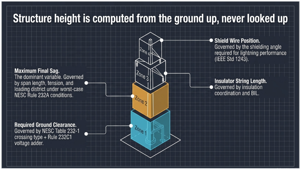
Height is a stack. Build it from the ground up.
- Required ground clearance — from NESC Table 232-1 for the crossing type, plus the Rule 232C1 voltage adder, plus altitude correction where it applies, plus whatever margin the utility's own standard adds on top.
- Maximum final sag at the governing condition — usually the single largest term, and set by span length, conductor type and tension, and the loading district.
- Insulator string length — the conductor attaches at the bottom of the string; the crossarm sits at the top of it.
- Shield wire position — set by the shielding angle needed for lightning performance, which puts the overhead ground wire above and usually inboard of the outer phases.
- Terrain and profile — the controlling point is wherever the ground rises under the span, not necessarily midspan.
Of these, span length is the dominant variable, and it interacts with terrain in a way that surprises people.
AEP's flat-terrain structures are taller than its hilly-terrain structures — 150 ft vs 135 ft at 765 kV. That looks backwards until you see the mechanism. Flat ground permits longer spans; longer spans mean more sag; more sag means more height. Terrain does not act on height directly. It acts through span, and it can act in either direction.
The condition the clearance is checked at
NESC Rule 232A specifies that the vertical clearances of Rule 232B1 apply under the following conductor temperature and loading conditions, whichever produces the largest final sag:
- 50 °C (120 °F), no wind displacement
- The maximum conductor temperature for which the line is designed to operate, if greater than 50 °C, with no wind displacement
- 0 °C (32 °F), no wind displacement, with the radial thickness of ice for the loading district
Three things to take from that.
It is final sag — long-term, after creep and after the conductor has taken its permanent set. Not initial sag, and emphatically not stringing sag.
It is the largest of three conditions, not a single design case. A line in a Heavy loading district may be governed by the iced condition; a line operating at 100 °C may be governed by the high-temperature condition. You check all three.
And it is at
maximum operating temperature, not at the temperature the line happened to be at when someone surveyed it. This is the single most common way an as-built line turns out to be non-compliant while every field measurement looked fine — see Case Study 1.
5. Worked example A — 115 kV single-circuit, road crossing
Design case. 115 kV single-circuit tangent structure, effectively grounded, crossing a two-lane road subject to truck traffic. Cross-country alignment, 800 ft ruling span, Medium loading district.
Step 1 — Required ground clearance
Table 232-1 base for open supply conductors over a road subject to truck traffic: 18.5 ft
Rule 232C1 adder: phase-to-ground = 115 / √3 = 66.4 kV; (66.4 − 22) × 0.4 in = 17.8 in = 1.48 ft
Required clearance = 20.0 ft. Utility standards commonly add a design buffer for survey tolerance, future road grading and conductor creep beyond the design assumption; carry 2 ft, giving a 22.0 ft design clearance at the controlling point.
Step 2 — Maximum final sag
From the sag-tension calculation for the actual conductor, ruling span, tension limits and loading district, checked against all three Rule 232A conditions. For this example, take the governing final sag at maximum operating temperature as 22 ft.
This number is not a lookup. It is the output of a sag-tension run, and it will move by several feet for the same span if you change conductor, tension limit, or loading district.
Step 3 — Build the stack
| Term | Value |
|---|---|
| Design ground clearance at controlling point | 22.0 ft |
| Maximum final sag (governing Rule 232A condition) | 22.0 ft |
| Conductor attachment elevation | 44.0 ft |
| Insulator string length (suspension) | ~5 ft |
| Crossarm elevation | ~49 ft |
| Shield wire above arm (shielding angle) | ~10 ft |
| Structure height above ground | ~59 ft |
Sanity check against published data. Georgia Transmission gives 115 kV single
poles 60–80 ft cross-country and 80–120 ft roadside. Our 59 ft lands right at the bottom of the cross-country band, which is what you would expect for a level crossing with no distribution underbuild and no roadside constraints. Roadside structures run taller because they carry underbuild, cross the road at unfavourable angles, and are set for future widening.
6. Worked example B — 500 kV single-circuit, same road crossing
Same crossing. Same terrain. Different voltage, and — critically — a different span.
Step 1 — Required ground clearance
Table 232-1 base: 18.5 ft. Rule 232C1 adder: phase-to-ground = 500 / √3 = 288.7 kV; (288.7 − 22) × 0.4 in = 106.7 in = 8.89 ft
Required clearance = 27.4 ft, plus a 3 ft buffer = 30.4 ft design clearance.
A note on method at EHV. Rule 232C1's linear adder is available for voltages between 22 and 470 kV, applied phase-to-ground — so it remains nominally available even at 765 kV, where phase-to-ground is 441.7 kV. But NESC Rule 232D, "Alternate clearances for voltages exceeding 98 kV ac to ground or 139 kV dc to ground," offers a switching-surge-based method that EHV designers normally use instead, because the linear adder is conservative at these voltages. Rule 232D requires the maximum switching-surge factor — the switching-surge level for circuit breakers corresponding to 98% probability, or the maximum anticipated level from other means, whichever is greater — and reference heights from Table 232-3. Above 470 kV, Rule 232D is mandatory, not optional. Work the actual numbers from the printed code.
Step 2 — Maximum final sag
500 kV lines run long spans. Take a 1,400 ft ruling span with a three-conductor bundle, governing final sag 45 ft.
Step 3 — Build the stack
| Term | Value |
|---|---|
| Design ground clearance at controlling point | 30.4 ft |
| Maximum final sag | 45.0 ft |
| Conductor attachment elevation | 75.4 ft |
| Insulator string length (suspension, 500 kV) | ~15 ft |
| Crossarm elevation | ~90 ft |
| Shield wire above arm | ~20 ft |
| Structure height above ground | ~110 ft |
AEP publishes 500 kV single-circuit at 120 ft hilly / 135 ft flat; CPUC gives 80–200 ft. Our 110 ft sits inside both.
Step 4 — Now compare the two examples
| Parameter | 115 kV | 500 kV | Difference |
|---|---|---|---|
| Rule 232C1 voltage adder | 1.5 ft | 8.9 ft | +7.4 ft |
| Maximum final sag | 22 ft | 45 ft | +23 ft |
| Insulator string | 5 ft | 15 ft | +10 ft |
| Shield wire offset | 10 ft | 20 ft | +10 ft |
| Total structure height | 59 ft | 110 ft | +51 ft |
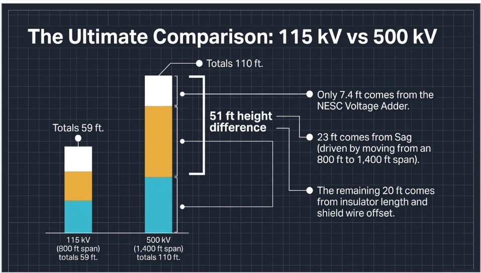
The structure is 51 ft taller. The voltage adder accounts for 7.4 ft of that — about 15%. The largest single contributor is sag, and sag came from choosing a 1,400 ft span instead of an 800 ft span.
Hold the voltage constant and change the span, and you move the height more than changing the voltage does. That is the finding, and it is why the lookup table on the poster cannot be used as a design tool.
Figure 1, on the following page, summarizes the whole argument: the height stack for both examples, the Rule 232C1 adder by voltage class, the published height ranges, and the capacity question addressed next.
FIGURE 1 — Where transmission structure height actually comes from: the height stack, the NESC Rule 232C1 voltage adder, published height ranges, and the capacity question

Illustrative design guidance — sag, insulator and shield-wire values are example inputs, not lookup values.
7. "Wider arms = more capacity" is backwards
The second claim in the key-points box is not a simplification. It is wrong, and it is wrong in a direction that can be demonstrated.
What actually sets phase spacing
Four things, none of which is capacity.
- Electrical clearance between phases under NESC Rule 235, "Clearance for wires, conductors, or cables carried on the same supporting structure."
- Insulator swing. Suspension strings blow out under transverse wind, carrying the conductor toward the structure. The arm must be long enough that the conductor maintains clearance to the steel at the design swing angle — RUS 1724E-200 tabulates swing angle values for exactly this purpose.
- Galloping. Conductors with asymmetric ice accretion oscillate in large low-frequency ellipses. Phase spacing must keep those ellipses from intersecting. The standard treatment is the Lissajous-ellipse method — CIGRE Technical Brochure 322, State of the Art of Conductor Galloping (WG B2.11, 2007).
- Switching surge withstand at EHV, which is the same physics driving Rule 232D.
Every one of those is a clearance requirement. None of them is a current-carrying or power-transfer requirement.
What actually sets capacity
Thermal rating — the current at which the conductor reaches its maximum allowable temperature, calculated per IEEE Std 738-2023, IEEE Standard for Calculating the Current-Temperature Relationship of Bare Overhead Conductors. It is a function of conductor size, material, surface condition, and the ambient conditions assumed — wind speed, air temperature, solar radiation. Phase spacing does not appear in it.
Surge impedance loading (SIL) — the natural loading of the line:
SIL = V(L-L)² / Zc where Zc = √(L / C)
SIL depends on line voltage and the distributed inductance and capacitance per unit length — and, as ERCOT puts it, "not the length of the line." Typical overhead surge impedance runs roughly 200–400 Ω.
And now the part that makes the claim backwards
Move the phases further apart and the loop area increases, so distributed inductance L rises. At the same time the conductors are further from each other and from ground, so distributed capacitance C falls. Both changes push Zc = √(L/C) up — and SIL = V²/Zc therefore goes down.
Wider arms slightly reduce surge impedance loading. They do not increase it. The claim is not merely unsupported; it has the sign wrong.
What does raise capacity: bundling
Here is the clean proof, from published ERCOT/MISO data:
| Configuration | SIL | Thermal rating |
|---|---|---|
| 345 kV single-circuit, 2-conductor bundle | 429 MW | 1,793 MVA |
| 345 kV double-circuit, 2-conductor bundle | 851 MW | 3,585 MVA |
| 345 kV double-circuit, 3-conductor bundle | 1,162 MW | — |
| 500 kV single-circuit, 3-conductor bundle | 936 MW | 2,744 MVA |
| 765 kV single-circuit, 6-conductor bundle | 2,435 MW | 6,625 MVA |
Compare rows two and three. Same voltage. Same number of circuits. Same structure geometry. Going from a two-conductor bundle to a three-conductor bundle raises SIL by 37% — because a larger bundle behaves like a larger effective conductor radius, which lowers Zc and raises both SIL and thermal rating at once. That is what buys capacity. Not arm width.
The line-length dimension
One more piece, because it determines which limit you are actually against. The St. Clair curve — H. P. St. Clair, Practical Concepts in Capability and Performance of Transmission Lines, AIEE 1953, given its analytical basis by Dunlop, Gutman and Marchenko in IEEE Trans. PAS, 1979 — divides lines into three regimes:
- Short lines: thermally limited. The conductor's temperature rating governs.
- Medium lines: voltage-drop limited. Typically a 5% drop criterion.
- Long lines: stability limited. MISO uses an angular displacement criterion of 44.5°; the stability regime typically begins around 300–500 km.
A short 345 kV line and a long 345 kV line have very different usable capacities with identical structures. Capacity is a system property, not a tower property.
8. Loading, strength and structure type
The graphic says nothing about what the structure has to survive, which is where most of the steel actually goes.
NESC Section 25 — loading districts
Rule 250B, combined ice and wind district loading, defines three districts:
| District | Radial ice | Wind pressure | Temperature | K |
|---|---|---|---|---|
| Heavy | 0.50 in (12.5 mm) | 4 lb/ft² (190 Pa) | 0 °F | 0.30 lb/ft |
| Medium | 0.25 in (6.5 mm) | 4 lb/ft² (190 Pa) | 15 °F | 0.20 lb/ft |
| Light | none | 9 lb/ft² (430 Pa) | 30 °F | 0.05 lb/ft |
The constant K is added to the resultant of the per-linear-foot weight, wind and ice loads.
Beyond the district case, Rule 250C covers extreme wind loading and Rule 250D covers extreme ice with concurrent wind. Rule 250C carries an exclusion for structures under 60 ft — an exclusion that several utilities and RTOs explicitly override in their own criteria. PJM, for one, states that the provision permitting exclusion of structures less than 60 ft from Rule 250C shall not apply. If you are designing to a transmission owner's criteria, read their overrides before you read the code.
The 2023 NESC replaced the extreme-wind speed maps in Figures 250-2(a) and 250-2(b) and reformatted Rule 250C1b. If you are carrying wind speeds forward from a 2017-edition design, check them.
Grades of construction and strength
Section 24 covers grades of construction — Grade B at crossings of limited-access highways, railroads and navigable waterways; Grade C elsewhere. Rule 261 carries the strength requirements, and Table 261-1 gives the strength factors: the permitted load is the designated strength of the structure multiplied by the applicable NESC strength factor.
Structure types and the ASCE layer
US practice uses lattice steel towers, tubular steel poles (single-circuit, double-circuit and H-frame), wood H-frames, concrete poles and guyed structures. The NESC sets the safety floor; the structural design comes from ASCE:
- ASCE Manual of Practice 74 (2020, 4th ed.) — Guidelines for Electrical Transmission Line Structural Loading
- ASCE/SEI 10-15 — Design of Latticed Steel Transmission Structures
- ASCE/SEI 48-19 — Design of Steel Transmission Pole Structures
- ASCE 7 wind and ice mapping, which utility practice commonly pairs with MOP 74 for construction and maintenance load cases alongside NESC 250C/250D
And RUS Bulletin 1724E-200, Design Manual for High Voltage Transmission Lines, remains the most complete free US reference for the whole chain — clearances in Chapter 4, ROW in Chapter 5, conductor-to-conductor and galloping in Chapter 6, insulator swing in Chapter 7, insulation in Chapter 8, loadings in Chapter 11, structures in Chapter 13, guyed structures in Chapter 14.
Right-of-way
Height's companion variable, and also not a voltage lookup — though it correlates more strongly. AEP publishes 200 ft for 765 kV single-circuit, 175–200 ft for 500 kV, and 150 ft for 345 kV single- or double-circuit. Georgia Transmission publishes roughly 100 ft for 115 kV, about 100 ft for 230 kV single pole and 125 ft for 230 kV H-frame, and 150–180 ft for 500 kV lattice. RUS 1724E-200 Table 5-3 is the canonical citable table.
9. Eight things worth correcting
1. Structure height is computed, not looked up. Ground clearance plus final sag plus insulator length plus shield wire position, driven mainly by span and terrain.
2. The voltage contribution is small and quantifiable. NESC Rule 232C1: 0.4 in per kV above 22 kV, applied phase-to-ground. From 115 kV to 500 kV that is 7.4 ft, against within-class published height ranges of 130 ft.
3. "Wider arms = more capacity" is backwards. Wider spacing raises Zc and therefore lowers SIL. Capacity comes from conductor size and bundling.
4. A height quoted without a span is not a design value. Span, conductor, tension and loading district all have to travel with the number.
5. One height does not apply to a whole line. The controlling ground point moves with the profile, and so does the required structure height.
6. 230 kV is HV, not EHV. ANSI C84.1 puts the EHV boundary above 230 kV.
7. Clearance is checked at final sag under the worst of three Rule 232A conditions — including maximum operating temperature — not at the sag you can measure on a mild day.
8. Circuit configuration outranks voltage. AEP's 345 kV double-circuit structures are taller than its 765 kV single-circuit structures.
10. Anonymized case studies
The following are anonymized and composited from typical engagements. Figures are representative of the scenarios described and have been rounded and adjusted; they do not identify any specific client or facility.
Case Study 1 — 138 kV rebuild: the survey that proved nothing
Situation. A utility completed a 12-mile 138 kV rebuild. The construction survey confirmed ground clearance at every road crossing with margin. Two summers later, during a regional heat event with the line loaded near its rating, a contractor working under the line reported clearance that looked visibly short at one crossing.
What the analysis found
The as-built survey had been performed in October at an ambient of about 55 °F, with the line lightly loaded. Measured conductor temperature was on the order of 60 °F. At that condition the clearance at the crossing was 24 ft — comfortably above the 20.4 ft required for 138 kV over a road subject to truck traffic.
The line's design maximum operating temperature was 212 °F. Under NESC Rule 232A, clearance must be verified at whichever of the three specified conditions produces the largest final sag — and for this line that was condition 2, the maximum operating temperature. Modelling the conductor at 212 °F final sag put clearance at the crossing at 19.1 ft, about 1.3 ft below the requirement.
Nothing had changed in the field. The survey had simply never been converted to the code condition.
What was done
The survey data was reprocessed properly: conductor positions were used to back-calculate tension at the measured temperature, and sag was then modelled at all three Rule 232A conditions across the whole rebuild. Four crossings were found short at maximum operating temperature; a fifth was short under the iced condition, which the utility had not been checking at all because the line was in a Light loading district and the team had assumed ice was not a case. It is a case — Light district specifies no radial ice, but the 0 °C condition still applies and can govern on short spans with high tension.
Two structures were raised, one span was re-tensioned, and the utility's survey procedure was rewritten to require the conversion to Rule 232A conditions as a deliverable rather than a subsequent analysis someone might or might not run.
Outcome
No incident. Four crossings corrected. The procedural change is the durable part — the utility now cannot close out a line survey without the clearance-at-governing-condition calculation attached.
Engineering takeaway
A clearance survey is a measurement of where the conductor was, not a demonstration that the line is compliant. Compliance lives at the Rule 232A governing condition, and getting from one to the other is a calculation that has to be somebody's named deliverable.
Case Study 2 — 230 kV greenfield: the height table that came from a poster
Situation. A developer's preliminary design for a 230 kV single-circuit line set a uniform 115 ft structure height across a 20-mile alignment, citing an internal "typical heights by voltage" table. Structure count, foundation quantities and the cost estimate were all built on that number, and the estimate went into a bid.
What the analysis found
The 115 ft figure had no derivation behind it. Traced back, it originated from a general-reference table of the same kind as the poster this article is about — a plausible midpoint presented as a design value.
Running the actual profile told a different story. On the flat southern third of the alignment, the terrain permitted 1,100 ft spans, and at that span the governing final sag required attachment heights that put structures at 130 to 140 ft. On the rolling northern section, ridge-to-ridge geometry gave shorter effective spans and the controlling ground points fell away under the conductor, so 90 to 100 ft structures were sufficient — and in three locations, 85 ft.
The uniform 115 ft assumption was simultaneously too short over a third of the line and too tall over another third. The too-short third was the expensive problem: it would have surfaced during detailed design, after the bid.
What was done
The alignment was resegmented into four span-and-height regimes driven by the ground profile rather than the voltage. Structure heights were derived from the clearance-plus-sag stack in each regime. Total steel tonnage rose about 6% against the original estimate; structure count fell, because the taller structures in the flat section carried longer spans. The developer's internal typical-heights table was retired and replaced with a one-page procedure that starts from the profile.
Outcome
The corrected quantities went into the bid. The 6% steel increase was a known number before award rather than a change order after it.
Engineering takeaway
A typical-heights-by-voltage table is a communication aid, not an estimating basis. The moment it enters a cost model it stops being a simplification and starts being a liability — and the error is not symmetric, because the too-short segments cost far more to fix than the too-tall segments save.
Case Study 3 — 345 kV uprate: the request for wider arms
Situation. A transmission owner facing a congested 345 kV corridor asked for a study on increasing transfer capability. The initiating request, written by a planner working from a general reference, proposed "widening the crossarms to increase the line's power transfer capacity" as one of the options to be evaluated.
What the analysis found
The option was evaluated, and it does not work — in fact it moves the wrong way.
Widening phase spacing increases the distributed inductance of the line and decreases its distributed capacitance. Surge impedance Zc = √(L/C) therefore rises, and since SIL = V²/Zc, surge impedance loading falls. The modelled effect of the proposed spacing increase was a reduction in SIL of a little under 2%. Thermal rating was unchanged, because conductor thermal rating under IEEE Std 738 is a function of the conductor and the ambient conditions, not of the geometry of the structure holding it.
The study also established which limit the line was actually against. At its length, the corridor sat in the voltage-drop-limited regime of the St. Clair curve — not the thermal regime — so a pure thermal uprate would not have delivered the transfer capability the planner wanted either.
What was done
Three options were carried forward: adding a third sub-conductor to the existing two-conductor bundle; reconductoring to a high-temperature low-sag conductor; and series compensation to address the voltage-drop limit directly.
Bundling came out ahead on capability per dollar. Published comparisons of 345 kV double-circuit configurations show the move from a two-conductor to a three-conductor bundle raising SIL by roughly 37% at identical voltage and circuit count — the mechanism being a larger effective conductor radius, which lowers Zc and raises both SIL and thermal rating together.
The catch, and the reason this was a structural study and not only an electrical one: a third sub-conductor adds weight and wind area, which changes sag, which changes clearance, and changes structure and foundation loading. The uprate was feasible, but it was a transmission line design problem, not a conductor swap.
Outcome
The corridor was uprated by bundling with structure reinforcement at 40% of the structures and clearance correction at eleven crossings. Arm width was never touched.
Engineering takeaway
Capacity lives in the conductor and the system; clearance lives in the geometry. When someone proposes a geometric change to solve a capacity problem, the first question is which of the two they have actually confused — and the second is which limit the line is really against, because a thermal fix does nothing for a stability-limited or voltage-drop-limited corridor.
11. Frequently asked questions
There is no answer to that question without a span, a conductor, a loading district, a ground profile and a crossing type. What the NESC gives you is the clearance floor: 18.5 ft base over roads subject to truck traffic plus a 3.7 ft voltage adder at 230 kV, so 22.2 ft. Everything above that comes from sag, insulator length and shield wire position. Published US ranges for 230 kV single poles run from about 70 ft to 200 ft depending on all of the above.
That for voltages between 22 and 470 kV, the Table 232-1 clearance is increased at 0.4 in (10 mm) per kV in excess of 22 kV, applied to the phase-to-ground voltage for effectively grounded circuits. Above 470 kV the clearance must instead be determined by Rule 232D.
Rule 232D — Alternate clearances for voltages exceeding 98 kV ac to ground or 139 kV dc to ground — is optional above 98 kV to ground and mandatory above 470 kV. In practice EHV designers use it well below the mandatory threshold because the linear adder is conservative at those voltages. It requires the maximum switching-surge factor (the 98%-probability breaker switching-surge level, or the maximum anticipated level from other means, whichever is greater) and reference heights from Table 232-3, with an altitude correction. Work it from the printed rule.
Per Rule 232A, at whichever of three conditions produces the largest final sag: 50 °C with no wind displacement; the maximum design operating temperature if above 50 °C, no wind; or 0 °C with the district radial ice thickness, no wind. Final sag, not initial and not stringing.
Not necessarily, and this is the most common false positive in the business. A survey captures the conductor at the temperature and tension it happened to have that day. Compliance is judged at the Rule 232A governing condition — commonly maximum operating temperature, after creep. The correct method is to survey the conductor position, back-calculate the tension at the measured temperature, and then model the sag at the governing condition. See Case Study 1.
No, and it slightly reduces surge impedance loading. Wider phase spacing increases distributed inductance and decreases distributed capacitance, which raises Zc = √(L/C); since SIL = V²/Zc, SIL falls. Thermal rating is unaffected — IEEE Std 738-2023 does not include phase spacing as a variable. Capacity comes from conductor size, bundle configuration, and the operating temperature limit.
Electrical clearance between phases under NESC Rule 235; insulator swing under transverse wind; galloping ellipse separation (CIGRE TB 322 and the Lissajous method); and switching surge withstand at EHV. All clearance criteria.
In rough order of cost: raise the operating temperature limit if the conductor and clearances permit it (which usually means re-checking Rule 232A clearance at the new temperature — the two are coupled); reconductor to a larger or higher-temperature conductor such as ACSS or an ACCC/ACCR type; add a sub-conductor to the bundle; rebuild at a higher voltage. Dynamic line rating can also unlock existing headroom without touching the steel. Each one interacts with clearance and structure loading, so none of them is purely an electrical decision.
Heavy, Medium or Light per the NESC Section 25 map, giving radial ice of 0.50 in, 0.25 in and none respectively, with wind pressures of 4, 4 and 9 lb/ft² and temperatures of 0 °F, 15 °F and 30 °F. But the district case is only the starting point — Rule 250C extreme wind and Rule 250D extreme ice with concurrent wind also apply, and many transmission owners override the NESC exclusions in their own criteria.
No. IEEE Std 998-2012 is Guide for Direct Lightning Stroke Shielding of Substations. For transmission lines, the applicable IEEE document is IEEE Std 1243, Guide for Improving the Lightning Performance of Transmission Lines, which covers overhead lines above 69 kV phase-to-phase with average conductor height over 10 m.
Rule 233 — clearances between wires, conductors and cables carried on different supporting structures. Rule 234 — clearance of wires, conductors, cables and equipment from buildings, bridges, rail cars, swimming pools, supporting structures and other installations. Rule 235 — clearance for wires, conductors or cables carried on the same supporting structure. Three different geometries, three different rules, routinely confused.
The edition adopted by the jurisdiction, which is not automatically the newest. NESC 2023 (IEEE C2-2023) was published 1 August 2022 and became effective 1 February 2023, on the standard five-year cycle. Note that it replaced the extreme-wind maps in Figures 250-2(a) and 250-2(b), and that an errata was issued 15 November 2023. If you are carrying loading assumptions forward from an earlier edition, verify them against the current maps.
Driven by right-of-way width, terrain access, foundation conditions, span length, circuit count, and increasingly by public acceptance and outage constraints during construction. Lattice remains common at EHV; tubular steel poles are widely used at HV where ROW is narrow. The structural design in each case follows ASCE 10-15 for lattice and ASCE 48-19 for steel poles, with loading from ASCE MOP 74 and the NESC.
Because flat ground permits longer spans, longer spans produce more sag, and more sag requires more height at the attachment point to preserve the same ground clearance. AEP's published figures show exactly this — 150 ft in flat terrain versus 135 ft in hilly at 765 kV. Terrain acts on height through span, and the sign can go either way.
More reliably than it means a taller structure, but still not by a fixed rule. AEP publishes 150 ft ROW for both 345 kV single-circuit and 345 kV double-circuit; Georgia Transmission publishes about 100 ft for both 115 kV and 230 kV single poles, but 125 ft for a 230 kV H-frame. ROW is set by horizontal clearance to objects and structures plus the circuit arrangement — configuration again, not just voltage.
12. Standards reference
| Standard | Scope |
|---|---|
| NESC — IEEE C2-2023 | National Electrical Safety Code; published Aug 2022, effective Feb 2023 |
| NESC Rule 232 / Table 232-1 | Vertical clearances of wires above ground, roadway and water surfaces |
| NESC Rule 232A | Conductor temperature and loading conditions for clearance verification |
| NESC Rule 232C1 | Voltage adder — 0.4 in per kV above 22 kV, 22 to 470 kV, phase-to-ground |
| NESC Rule 232D | Alternate clearances above 98 kV ac to ground; mandatory above 470 kV |
| NESC Rule 233 | Clearances between conductors on different supporting structures |
| NESC Rule 234 | Clearance from buildings, bridges, rail cars, swimming pools and other installations |
| NESC Rule 235 | Clearance between conductors on the same supporting structure |
| NESC Section 24 / Rule 261 | Grades of construction; strength requirements and Table 261-1 strength factors |
| NESC Section 25 / 250B, 250C, 250D | District ice and wind loading; extreme wind; extreme ice with concurrent wind |
| ANSI C84.1-2020 | Nominal and maximum system voltages; HV / EHV definitions |
| IEEE Std 738-2023 | Current-temperature relationship of bare overhead conductors |
| IEEE Std 1243-1997 | Improving the lightning performance of transmission lines (>69 kV) |
| IEEE Std 998-2012 | Direct lightning stroke shielding of substations |
| IEEE Std 524-2016 | Installation of overhead transmission line conductors |
| IEEE Std 691-2001 (R2007) | Transmission structure foundation design and testing |
| IEEE Std 1724-2011 | Preparation of a transmission line design criteria document |
| ASCE MOP 74 (2020) | Guidelines for electrical transmission line structural loading |
| ASCE/SEI 10-15 | Design of latticed steel transmission structures |
| ASCE/SEI 48-19 | Design of steel transmission pole structures |
| RUS Bulletin 1724E-200 | Design manual for high voltage transmission lines |
| CIGRE TB 322 (2007) | State of the art of conductor galloping (WG B2.11) |
| St. Clair (1953); Dunlop et al. (1979) | Transmission line loadability characteristics |
Closing
The poster is a teaching aid, and as a teaching aid it is defensible. Higher voltage really does mean lower current, lower loss and — on average — bigger structures. Someone seeing a transmission line for the first time is better off with that mental model than with none.
The trouble starts when it leaves the classroom. A height-by-voltage table looks exactly like a design table, and it is not one. It contains no span, no conductor, no loading district, no ground profile and no crossing type — which is to say it contains none of the variables that actually set the number it reports. Put it in a cost model and it becomes a liability, as Case Study 2 shows. Put its second claim into an uprate study and it points the work in the wrong direction entirely, as Case Study 3 shows.
The honest version is less quotable and more useful: structure height is the sum of a required clearance, a computed sag, an insulator string and a shield wire offset — and span and terrain move it more than voltage does.
At Keentel Engineering, transmission line design, NESC clearance and sag-tension analysis, structure loading, and power system studies are delivered together, because the questions above do not stay in one discipline — a capacity study becomes a clearance study becomes a foundation study. If you have a line to route, a clearance survey to reconcile against Rule 232A, a corridor to uprate, or a typical-heights table you are not sure about, we would be glad to look at it.
KEENTEL ENGINEERING
Tampa, FL · Austin, TX · Sacramento, CA · Baltimore, MD
keentelengineering.com · contact@keentelengineering.com · 813-389-7871
Engineering note: NESC rule numbers and values are given for the 2023 edition (IEEE C2-2023) and were verified against published sources at time of writing; confirm against the edition adopted in your jurisdiction and against the printed code, particularly for Table 232-1 rows and the Rule 232D method, which should be worked from the code text rather than any secondary source. Sag values, insulator string lengths and shield wire offsets in the worked examples are illustrative design inputs, not lookup values. Nothing here substitutes for a project-specific engineering design.

About the Author:
Sandip "Sonny" R. Patel, P.E.
IEEE Senior Member · Founder & CEO, Keentel Engineering
In 1995, Sonny Patel earned his Electrical Engineering degree from the University of Illinois. But degrees don't build legacies — action does.
For three decades, he has worked the power industry from every side of the table: 16 years as a utility engineer at Exelon/Commonwealth Edison; generation leadership across hydroelectric, industrial steam turbine, and a 9 GW renewable fleet; NERC Regional Entity Senior Compliance Engineer and Audit Team Lead, auditing some of the nation's largest utilities; and testing and commissioning lead on equipment up to 765 kV — the very top of the North American grid.Utility. Generator. Regulator. Consultant. Few engineers have seen all four seats. Fewer still have sat in them.
His experience spans nuclear, hydro, conventional generation, renewables, oil and gas, mining — and today's data centers, where he is authoring a three-book series on data center design. He is a Licensed Professional Engineer in six states and a Licensed Electrical Contractor in Florida (Unlimited EC) — he doesn't just design the work; he's qualified to stand behind its execution.Today, as Founder and CEO of Keentel Engineering, Sonny leads a nationwide team of engineers delivering substation design, power system studies, NERC compliance, and commissioning — done right, coast to coast.Three decades. Every side of the table. One standard: accountable engineering.
Services

Let's Discuss Your Project
Let's book a call to discuss your electrical engineering project that we can help you with.
About the Author:
Sandip "Sonny" R. Patel, P.E.
IEEE Senior Member · Founder & CEO, Keentel Engineering
In 1995, Sonny Patel earned his Electrical Engineering degree from the University of Illinois. But degrees don't build legacies — action does.
For three decades, he has worked the power industry from every side of the table: 16 years as a utility engineer at Exelon/Commonwealth Edison; generation leadership across hydroelectric, industrial steam turbine, and a 9 GW renewable fleet; NERC Regional Entity Senior Compliance Engineer and Audit Team Lead, auditing some of the nation's largest utilities; and testing and commissioning lead on equipment up to 765 kV — the very top of the North American grid.
Utility. Generator. Regulator. Consultant. Few engineers have seen all four seats. Fewer still have sat in them.
His experience spans nuclear, hydro, conventional generation, renewables, oil and gas, mining — and today's data centers, where he is authoring a three-book series on data center design. He is a Licensed Professional Engineer in six states and a Licensed Electrical Contractor in Florida (Unlimited EC) — he doesn't just design the work; he's qualified to stand behind its execution.
Today, as Founder and CEO of Keentel Engineering, Sonny leads a nationwide team of engineers delivering substation design, power system studies, NERC compliance, and commissioning — done right, coast to coast.Three decades. Every side of the table. One standard: accountable engineering.
Leave a Comment
Thank you for contacting us.
We will get back to you as soon as possible.
We will get back to you as soon as possible.
Oops, there was an error sending your message.
Please try again later.
Please try again later.
Related Posts

By SANDIP R PATEL
•
October 3, 2026
Engineering guide to PRC-028 disturbance recording, PRC-029 ride-through and PRC-030 event detection for inverter-based resources.

By SANDIP R PATEL
•
October 3, 2026
A practical guide to SSO classification, SSR, PEDI, Wind-SSCI, EMT analysis, mitigation and protection based on CIGRE TB 909.

By SANDIP R PATEL
•
October 3, 2026
Learn ERCOT generator testing for PFR, MOD-025 and MOD-026/027, including staged tests, capability verification, dynamic models and field testing.

By SANDIP R PATEL
•
October 3, 2026
Learn how PV string I-V curve testing identifies hidden solar performance losses, including soiling, shading, mismatch, degradation, and wiring faults.

By SANDIP R PATEL
•
October 3, 2026
Learn how active harmonic filters work, how to size AHF systems, reduce VFD harmonics, calculate losses, and meet IEEE 519 TDD limits at the PCC.
By SANDIP R PATEL
•
October 3, 2026
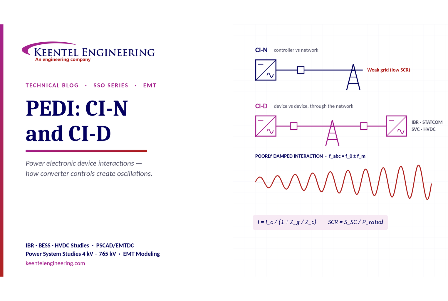
Learn power electronic device interactions (PEDI), including CI-N and CI-D, weak-grid stability, SCR, EMT studies, impedance analysis and mitigation for IBRs.
By SANDIP R PATEL
•
October 3, 2026
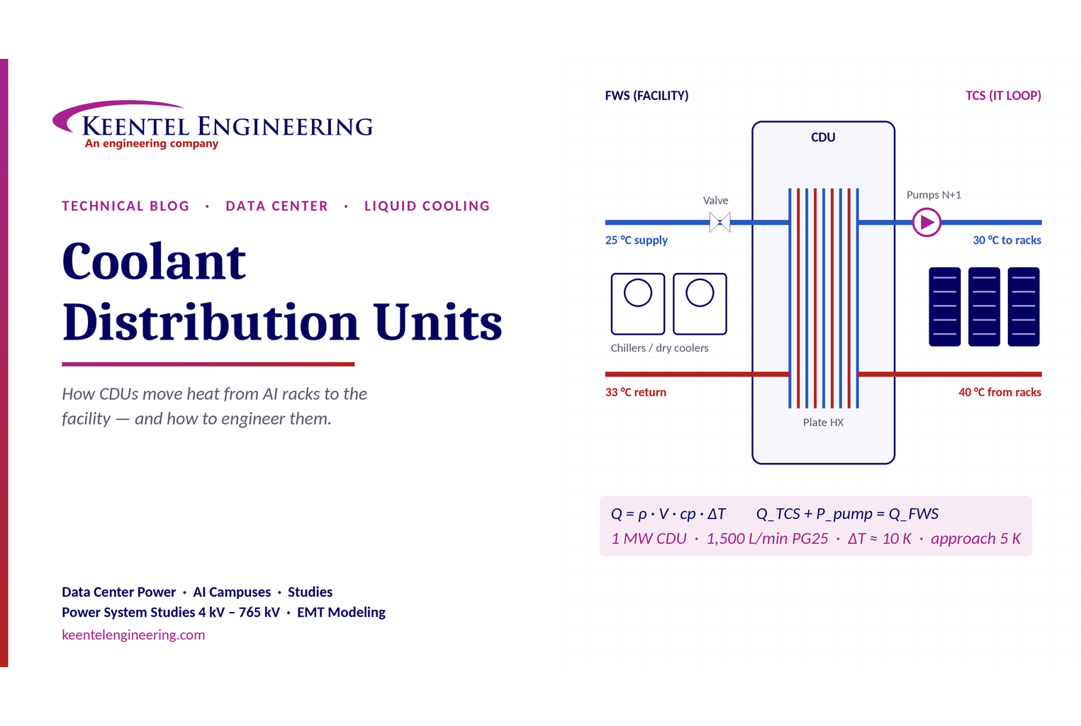
Learn how data center coolant distribution units (CDUs) work, including FWS and TCS loops, heat transfer, sizing, redundancy and liquid cooling for AI data centers.
By SANDIP R PATEL
•
October 3, 2026
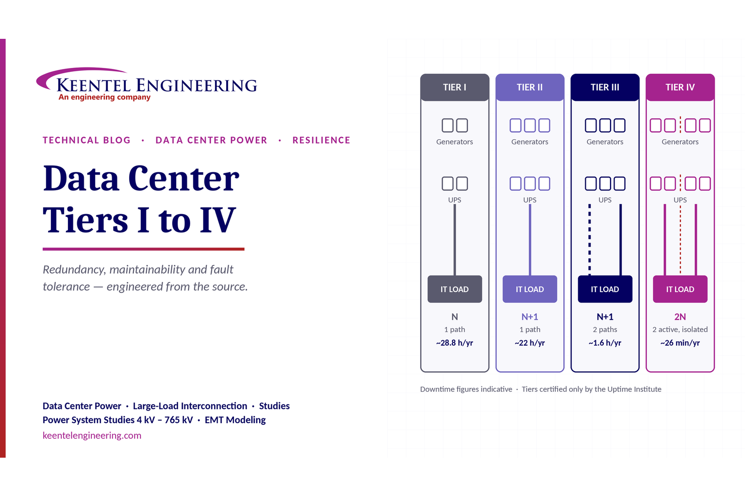
Compare Data Center Tiers I–IV, including redundancy, uptime, Tier III concurrent maintainability, Tier IV fault tolerance, UPS, generators and power design.

By SANDIP R PATEL
•
October 3, 2026
Learn how BESS supports grid stability through fast frequency response, voltage support, oscillation damping, black start, grid-forming controls and EMT studies.





