A Coordinated Electric System Interconnection Review—the utility’s deep-dive on technical and cost impacts of your project.
Challenge: Frequent false tripping using conventional electromechanical relays
Solution: SEL-487E integration with multi-terminal differential protection and dynamic inrush restraint
Result: 90% reduction in false trips, saving over $250,000 in downtime
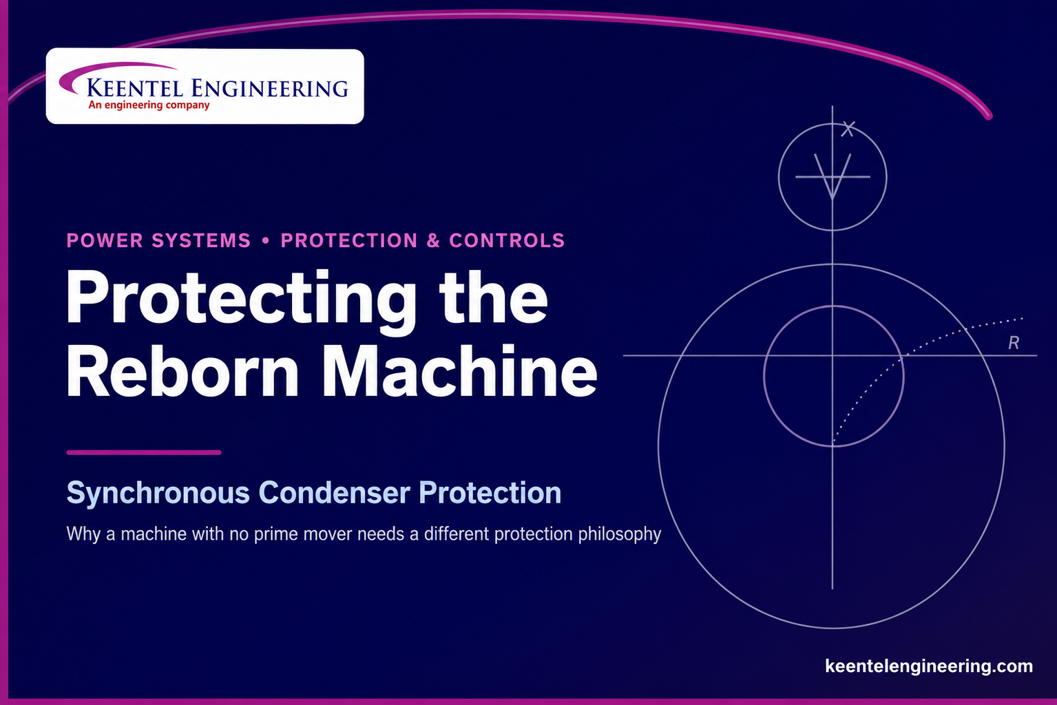
The Synchronous Condenser Is Back — and Its Protection Is Not Just “Generator Protection”
May 11, 2026 | Blog
For most of the last half-century, the synchronous condenser was treated as a relic. As static reactive devices such as SVCs and STATCOMs matured, many utilities retired their spinning condensers and never looked back. That decision is being reversed across North America right now, and the reason is structural: the grid is losing the very machines that quietly held it together.
As coal and older gas plants retire and inverter-based resources (IBR) — utility-scale solar, wind, and battery storage — take their place, two physical quantities decline that no inverter fully replaces: short-circuit strength and rotational inertia. Inverters follow the grid; they do not, on their own, anchor it. Where penetration is high and the network is electrically weak, the symptoms are familiar to anyone who has run an interconnection study lately: low short-circuit ratio (SCR) at the point of interconnection, control interactions and sub-synchronous oscillations, sluggish voltage recovery after faults, and ride-through performance that is difficult to certify.
Layered on top of that is the largest load-growth event in a generation. Hyperscale data centers and AI campuses are arriving as hundreds of megawatts of fast, concentrated, power-electronic demand — and they want to interconnect into precisely the weak pockets where system strength is already thin. Equipment vendors have noticed; several have recently launched synchronous condenser packages aimed squarely at stabilizing the grid around large data-center loads. The condenser is no longer a museum piece. It is a strategic asset.
A synchronous condenser delivers three things an inverter cannot replicate on demand: a robust, fault-current source that raises local system strength; genuine rotational inertia from a spinning mass that slows the rate-of-change-of-frequency during disturbances; and smooth, continuous dynamic voltage support whose reactive output does not collapse with terminal voltage the way some static devices do. Add a flywheel and the inertia contribution grows further.
Where the condensers are coming from
Two supply paths dominate. The first is the purpose-built machine: a new synchronous condenser, often with a flywheel, specified explicitly for grid strength. The second — frequently the more economical — is conversion. A retired steam turbogenerator, an idle combustion turbine, or a hydro unit with surplus capability can be repurposed into a condenser by decoupling the prime mover. The generator that used to make megawatts becomes a machine that makes vars and fault current instead.
Conversion approaches vary with how often the unit will switch modes. A hydro machine can simply close its wicket gates and spin in air (with a blowdown/air-evacuation system if the runner sits below tailwater). A combustion turbine can declutch its engine after synchronizing. A steam unit is typically decoupled by a clutch for frequent switching, or by a bolted shaft flange when the change is effectively permanent, with the turbine blades sometimes removed entirely to avoid windage losses. Auxiliary systems — lube oil, turning gear, stator cooling — often must be retained, and the unit needs a starting means (static starter or pony motor) because there is no longer a prime mover to bring it up to speed.
So why isn’t the protection just “copy the generator settings”?
Because one physical fact changes the dynamics of the whole machine: a synchronous condenser has no source of mechanical input power. It does not export real power. In steady state it actually draws a small amount of real power from the system to overcome friction and windage — it lives almost entirely on the reactive (vertical) axis of the capability curve, slightly into the motoring region. Electrically, the stator winding, rotor, field winding, and excitation system look just like a generator’s, so many protection functions carry over unchanged. But the functions that depend on mechanical input power — and there are several — behave very differently, and a few generator protections become unnecessary or even counterproductive.
The one-sentence version
Treat the stator, rotor, field, and ground-fault protection like a generator—but rethink loss of field, loss of synchronism, inadvertent motoring, and frequency protection from first principles, because a machine with no accelerating power source cannot misbehave the way a generator does.
The headline example is loss of field. On a generator, the apparent-impedance trajectory after a loss-of-excitation event depends on how much real power the unit was carrying, which is why conventional schemes often use two mho zones to stay both secure and dependable across loading conditions. A condenser carries no real power, so its loss-of-field signature is a single, predictable impedance swing — and a single mho element, set from the machine’s own reactances, is sufficient. Simpler, and more secure.
The mirror-image example is pole slipping. A generator slips a pole when a fault traps mechanical energy in the rotor and the rotor angle runs past 180 degrees. A synchronous condenser has no prime mover pushing the shaft, so there is no accelerating energy to store. It can lose voltage synchronism, but transient and EMT studies consistently show the rotor angle oscillating within a bounded window — nowhere near a pole slip — so dedicated out-of-step protection is usually unnecessary for the condenser itself.
Get these distinctions right and you end up with a protection package that is leaner, more secure against misoperation, and fully defensible in a NERC PRC review. Get them wrong — by porting a generator template wholesale — and you risk nuisance trips of an asset whose entire job is to stay connected and hold the grid up during the exact disturbances that would trip it. The sections that follow lay out the engineering in detail, walk through three anonymized projects, and answer the questions we hear most often.
Technical Deep-Dive: A Protection Philosophy for Synchronous Condensers
This section is written for the protection engineer who has to specify relays, calculate settings, and defend them. It maps each function against synchronous-condenser physics and flags where the condenser departs from IEEE C37.102 generator practice. The governing references throughout are IEEE C37.102 (AC generator protection), C37.101 (generator ground protection), C37.106 (abnormal frequency), C37.119 (breaker-failure), C37.2 (device function numbers), and C50.12/C50.13 (machine ratings), together with NERC PRC-019-2 and PRC-024-4 for compliance.
1. The machine, in three properties
- No mechanical input power. There is no prime mover delivering torque to the shaft, so there is no accelerating-power source. The condenser absorbs a small real power (friction and windage) and otherwise operates on the reactive axis — overexcited to supply vars, underexcited to absorb them.
- Electrically identical to a generator. Same stator winding, same rotor and field winding, same excitation system and limits. Stator, field, and ground-fault protection transfer over directly.
- A strong fault-current source. Behind subtransient, then transient, then synchronous reactance, the machine delivers substantial short-circuit current independent of whether anything is coupled to the shaft. This is a feature — it is much of the reason the condenser was installed — but it must be respected in backup and breaker-failure design.
2. Functions that transfer over from generator practice
These follow C37.102/C37.101 essentially unchanged. Dual (redundant) protection systems are recommended for dependability, typically two independent multifunction generator/motor relays. Relay manufacturers have not historically built a dedicated condenser relay, but standard generator or synchronous-motor multifunction relays implement everything needed.
| Function (device) | Condenser treatment |
|---|---|
| Field winding overcurrent | Same field thermal limits as a generator; apply overload protection per C37.102. |
| Stator differential (87) | Standard percentage-differential zone protects the stator winding for internal faults. |
| Stator ground fault (59G / 64S / 27TH / 59THD) | Neutral-derived schemes per C37.101/C37.102; selection depends on the grounding method (distribution-transformer or directly connected resistor). |
| Field-circuit ground (64F) | No difference from other synchronous machines. |
| Backup distance / voltage-restrained OC (21, 51V) | Required: the condenser is a strong source into grid faults. Coordinate with the upstream transmission scheme (use distance backup where the lines use distance). |
| Breaker-failure (50BF) | Generator breaker-failure logic per C37.102 / C37.119 applies. |
| Stator overflux V/Hz (24) | Still needed — see Section 4. Field forcing can overexcite the core even at synchronous speed. |
| Negative-sequence / unbalance (46) | Still needed — see Section 4. Same rotor I₂²t limit as a generator. |
3. Loss of field (40): the defining difference
On a synchronous generator, the post-event apparent impedance depends on pre-fault MW loading, which spreads the trajectory across the R-X plane and motivates dual-zone mho schemes. A condenser carries no MW, so its behavior is singular and predictable.
Map P-Q to R-X. The terminal apparent impedance relates to output by R = V²P/(P²+Q²) and X = V²Q/(P²+Q²). Producing vars places the impedance in the second quadrant; absorbing vars places it in the third. At zero var and a small incoming MW, the impedance sits far out along the negative-R axis — for a 20 kV machine drawing roughly 1 MW at zero var, on the order of –400 Ω.
The swing. When excitation is lost, var output decays and the machine drifts toward induction-motor behavior. Flux collapses, the machine transitions through a purely-resistive point, then begins absorbing vars and the locus migrates toward the third quadrant. Plotted on the loss-of-field scale, the trajectory traces a large, single circular swing — there is no second family of trajectories to guard against.
Recommended single-mho setting (negative-offset method, C37.102 Method 1)
- Diameter = Xₑ (synchronous reactance), scaled to secondary ohms by CTR/VTR.
- Offset = X′ₑ / 2 (half the transient reactance), the same negative offset used for generators.
- Time delay = 0.5 to 0.6 s, which initiates shutdown well inside the rotor and end-iron withstand times for a condenser-scale slip.
A second zone is unnecessary for a dedicated condenser because the final trajectory approaches Xₑ. Coordinate the circle against the underexcited edge of the capability curve, the steady-state stability limit (SSSL), and the underexcitation limiter (UEL).
Worked illustration: for a 13.8 kV, 330 MVA class machine with Xₑ ≈ 1.71 pu and X′ₑ ≈ 0.43 pu (Z-base ≈ 0.577 Ω, CTR 3000:1, VTR 120:1), the diameter works out near 25 Ω secondary and the offset near 3 Ω secondary — a clean, single circle. The calculation method is identical to a generator; only the second zone is dropped.
4. Functions that still matter — and need extra care
Negative-sequence / unbalance (46)
The condenser has the same rotor thermal vulnerability to negative-sequence current (the I₂²t limit) as a generator, even though it carries no balanced MW load. The watch item is the grid trend: as IBR penetration rises, some networks adopt slower fault-clearing schemes. Longer clearing times mean longer negative-sequence exposure for the condenser rotor during unbalanced grid faults, so coordinate the relay’s short-time capability against the actual (possibly extended) clearing times rather than legacy assumptions.
Stator overflux / V/Hz (24)
Flux is proportional to voltage and inversely proportional to frequency. A condenser’s excitation system can push terminal voltage above 1.0 pu through field forcing, overexciting the core even at synchronous speed on a stable-frequency system. Apply a V/Hz or phase-overvoltage scheme per C37.102/C37.106, and coordinate it with the excitation V/Hz limiter for PRC-019 compliance.
Inadvertent energization (50/27) and out-of-phase synchronization
Inadvertent energization (closing onto a de-excited, stationary machine) drives the unit as an induction motor. A condenser’s unloaded rotor demands less starting torque and current than a loaded motor, but the machine may still not tolerate an across-the-line start unless it was designed for one. Default to applying the scheme unless the OEM confirms the machine can withstand an unexpected across-the-line start; for machines that are intentionally induction-started, the scheme can instead be implemented as a supervisory control interlock that is disabled during a deliberate start. For out-of-phase synchronizing, the condenser is subject to the same electromagnetic/torque constraints as a generator because it has an internal voltage source — full sync-check supervision (magnitude, angle, slip) is warranted unless an across-the-line start sequence is used.
Sub-synchronous oscillations (SSO)
A multi-mass shaft near series capacitor compensation, an HVDC converter, or dense IBR can exchange energy at sub-synchronous frequencies with the shaft’s torsional modes. The risk is small for a compact condenser with a pony motor and brushless exciter, but rises for larger machines carrying a flywheel’s additional inertia. Where EMT studies of the IBR/HVDC controls flag interaction, add torsional monitoring and protection alongside any mitigation. Conventional generator schemes will not detect SSO.
5. Functions that are typically not needed — and why
Loss of synchronism / out-of-step (78)
A condenser cannot slip a pole. With no prime mover there is no accelerating power, and a flywheel is only a passive load. It can lose voltage synchronism if its internal voltage magnitude or angle drifts past the system, but transient and EMT simulations show bounded rotor-angle oscillation (on the order of tens of degrees for nearby three-phase faults), with the impedance locus oscillating near the X-axis and never reaching the electrical center. If an application still warrants the function, use a security-biased single-blinder scheme.
Inadvertent motoring / reverse power (32)
The condenser is designed to motor — it absorbs a little real power by definition, and there is no prime mover to protect from motoring. The function is therefore not required to protect the machine. One useful exception: on a hydro unit that naturally motors, a reverse-power element can still serve as a breaker-failure detector if power keeps flowing in after a shutdown command.
Abnormal frequency (81) and stator overcurrent (51)
Frequency protection guards prime-mover blades against resonance and supports load-rejection / anti-islanding logic that hinges on real-power balance. A condenser has no blades and no real-power role, so neither rationale applies. Stator overcurrent is generally unnecessary too:
condensers are built with large overload capability per C50.12/C50.13 and, lacking a prime mover, will not carry sustained balanced three-phase overload.
6. Special case: a single interconnecting line, or a weak system
The “condenser can’t slip a pole” conclusion is about the condenser in isolation. When a much larger synchronous generator shares the bus and slips poles, the condenser’s voltages, currents, and impedance locus get badly perturbed — it simply follows the dominant machine. The sharper risk is a facility tied to the transmission system through a single line, or into a weak system: once islanded, the condenser tracks whatever else is in the island. The mitigation is not more condenser protection but anti-islanding / out-of-step logic at the line terminal that detects separation and trips every unit in the facility.
7. NERC compliance: yes, the PRC standards apply
PRC-019-2 applies to individual synchronous condensers above 20 MVA directly connected to the Bulk Electric System. It requires coordination, reviewed at least every five years, of the voltage-regulating controls and in-service limiters (UEL, OEL, V/Hz limiter) with the machine’s capability and the protection settings — most visibly the loss-of-field mho against the UEL and SSSL, and the V/Hz relay against the excitation V/Hz limiter. PRC-024-4 — updated in 2024 — now explicitly names synchronous condensers: frequency and voltage protection settings must sit outside the no-trip ride-through envelopes, because the condenser is expected to ride through exactly the excursions it was installed to help damp. PRC-025-2 (relay loadability) and PRC-026 (relay performance during stable power swings) round out the review.
Keentel’s
protection settings and NERC O&P compliance teams build the LOF / UEL / SSSL / V/Hz coordination package and the PRC-024-4 ride-through documentation as part of the same
Case Studies
Project identities are confidential
The following studies are drawn from representative Keentel engagements. Client names, exact locations, one-line identifiers, and proprietary equipment data have been removed or generalized. Machine ratings and findings are illustrative of the engineering approach and do not disclose any specific client asset.
Case Study 1 — Retired Steam Turbogenerator Converted to a Dedicated Synchronous Condenser
| Client | Vertically integrated utility (confidential) |
|---|---|
| Location | Confidential — U.S. interior interconnection |
| Asset | Former coal-fired steam turbogenerator, ~300 MVA class, 13.8 kV, repurposed as a dedicated condenser |
| Keentel scope | Protection philosophy, relay specification, settings & coordination, PRC-019-2 / PRC-024-4 package, owner’s engineer support |
Challenge
A unit nearing the end of its life as a generator was structurally sound electrically. The utility wanted to retain its fault-current and inertia contribution in a corner of the system where retirements had eroded short-circuit strength. The turbine was to be permanently decoupled by a bolted shaft flange, with a static starting system bringing the machine to synchronous speed. The legacy generator protection — including dual-zone loss of field, reverse power, and frequency elements — could not simply be carried forward.
Approach
- Re-scoped the protection from first principles: retained stator differential (87), stator and field ground-fault, field overcurrent, negative-sequence (46), V/Hz (24), backup distance (21) and voltage-restrained overcurrent (51V), and breaker-failure — implemented across two independent multifunction relays for redundancy.
- Replaced the dual-zone loss-of-field scheme with a single negative-offset mho element (diameter = Xₑ, offset = X′ₑ/2, ~0.5 s delay), verified against the underexcited capability edge, the SSSL, and the underexcitation limiter.
- Removed inadvertent-motoring (32) and abnormal-frequency (81) protection as inapplicable; documented the engineering basis for each removal to support the compliance file and future audits.
- Retained an inadvertent-energization scheme because the decoupled machine was not rated for an across-the-line induction start, with interlocks disabled during the static-start sequence.
- Built the PRC-019-2 coordination plots (LOF vs UEL/SSSL, V/Hz relay vs excitation limiter) and PRC-024-4 ride-through documentation in the same pass.
Outcome
A leaner, more secure protection package with two fewer trip paths than the ported generator template, a single defensible loss-of-field circle, and a complete NERC PRC evidence file delivered with the settings — reducing nuisance-trip exposure on an asset whose value is measured by how reliably it stays connected during disturbances.
Case Study 2 — Dual-Mode Hydro Unit Operating as Generator and Condenser
| Client | Hydro generation owner (confidential) |
|---|---|
| Location | Confidential — hydroelectric facility |
| Asset | Salient-pole hydro machine, ~45 MVA class, 13.8 kV, switching between generate and condense modes |
| Keentel scope | Loss-of-field study (two operating modes), negative-sequence coordination, reverse-power application review, settings |
Challenge
The owner operated a hydro unit that needed to provide active power when water was available and reactive support / system strength when it was not (low water, or off-peak). Closing the wicket gates lets the runner spin in air; an air-evacuation system holds water below the runner. Because the same machine operates in both modes, the protection had to be valid across two very different capability footprints — a generator carrying MW, and a condenser on the reactive axis — without compromising security in either.
Approach
- Specified a two-zone loss-of-field scheme: the unit genuinely needs both zones because it loads up as a generator in one mode, while a single larger zone would suffice if it were condense-only. We sized both zones and verified the condense-mode trajectory against the smaller zone.
- Ran a dynamic loss-of-field simulation in condense mode (machine supplying vars, field breaker opened) and confirmed the rotor, stator-winding, and stator end-iron withstand times all exceeded the mho-plus-delay trip time — i.e., the negative-offset mho protects without exposing the machine to asynchronous-operation damage.
- Coordinated negative-sequence (46) protection against the rotor I₂²t capability, explicitly accounting for the longer fault-clearing times trending into the surrounding IBR-rich network so the rotor is protected during extended unbalanced grid faults.
- Applied a reverse-power element not as anti-motoring protection (the hydro unit naturally motors a few tenths of a percent in condense mode) but as a breaker-failure detector — flagging real power still flowing into the machine after a shutdown command.
Outcome
A single relay configuration valid in both operating modes, with simulation-backed evidence that the loss-of-field scheme trips inside the machine’s thermal withstand and that negative-sequence settings hold up under the grid’s evolving (slower) clearing times — protection that follows the machine rather than fighting its mode changes.
Case Study 3 — New-Build Condensers for Grid Strength at a Large-Load / Renewable Hub
| Client | Developer / load-serving entity (confidential) |
|---|---|
| Location | Confidential — low-inertia, IBR-rich pocket |
| Asset | Purpose-built synchronous condensers (flywheel-equipped) supporting a co-located renewable + large-load campus |
| Keentel scope | POI system strength & SCR study, EMT/SSO screening, protection philosophy, inadvertent-energization & anti-islanding design |
Challenge
A large concentrated load (data-center class) was interconnecting alongside utility-scale renewables into an electrically weak pocket with low short-circuit ratio. The developer needed condensers to lift system strength enough to certify IBR ride-through and stabilize voltage — but the same weak network, with nearby series compensation and dense inverters, raised sub-synchronous interaction concerns, and a portion of the facility tapped the transmission system through effectively a single path.
Approach
- Quantified the system-strength deficit at the point of interconnection (SCR / effective SCR) and sized the condenser fault-current contribution to meet the minimum strength needed for IBR stability and ride-through certification.
- Screened sub-synchronous oscillation risk with EMT models of the IBR and series-compensation controls; because the machines carry flywheels (added inertia, larger effective mass), specified torsional monitoring and protection where the study flagged interaction — conventional generator schemes do not detect SSO.
- Built the condenser protection on the lean baseline (single-mho LOF, 87, 46, 24, ground-fault, backup, breaker-failure), explicitly omitting 78 / 32 / 81 with documented justification.
- Applied inadvertent-energization protection as a control interlock for machines intended to be started in a controlled sequence, preventing human-error across-the-line starts.
- Addressed the single-line / weak-system case with anti-islanding and out-of-step logic at the transmission-line terminal — not on the condenser — to trip the whole facility cleanly on separation, since an islanded condenser merely follows the dominant machine.
Outcome
A condenser fleet sized to the measured strength deficit, an SSO screening that turned a latent torsional risk into a monitored-and-protected one, and a protection architecture that places stability/anti-islanding logic where it actually belongs — at the interconnection — giving the developer a defensible interconnection package for a weak-grid, large-load site.
About Keentel Engineering
Keentel Engineering is a power systems and grid-interconnection firm serving utilities, developers, and large-load customers from offices in Tampa, Florida and Austin, Texas. Our work spans power system studies across EHV, HV, and MV networks; point-of-interconnection engineering for utility-scale renewables, storage, and large loads; substation and transmission-line design; protection and controls; owner’s engineer services; and NERC operations & planning compliance.
On synchronous condenser projects we cover the full electrical scope: feasibility and conversion engineering, system-strength and short-circuit studies, protection philosophy and settings, EMT / sub-synchronous screening, and the PRC-019-2 / PRC-024-4 compliance package — whether the machine is a purpose-built condenser or a retired generator being given a second life as grid-strength infrastructure.
Disclaimers
Independence and non-affiliation.
Keentel Engineering is an independent engineering firm and is not affiliated with, sponsored by, or endorsed by IEEE, NERC, any regional transmission organization or independent system operator, or any equipment manufacturer. References to IEEE standards (including C37.102, C37.101, C37.106, C37.119, C37.2, and C50.12/C50.13) and to NERC Reliability Standards (including PRC-019-2, PRC-024-4, PRC-025-2, and PRC-026) are made solely to identify the governing technical framework. All trademarks and standard designations are the property of their respective owners.
Confidentiality.
All project examples in this paper are anonymized. No client names, project identifiers, exact locations, or proprietary equipment data are disclosed. Machine ratings and outcomes are illustrative of engineering approach only.
No engineering advice.
This paper is general technical information, not project-specific engineering advice. Protection settings must be developed for the specific machine, grounding, and interconnection by a qualified engineer, in coordination with the equipment manufacturer and the interconnecting entity, and verified against the applicable standards and the original-equipment-manufacturer documentation.
Frequently Asked Questions
Q. What exactly is a synchronous condenser, and how is it different from a generator?
It is a rotating synchronous machine connected to the grid with no prime mover — no turbine driving the shaft. It does not produce real power (it draws a little to cover friction and windage). Instead it generates or absorbs reactive power by modulating its DC field, supplies short-circuit current, and contributes rotational inertia. Electrically it looks like a generator; mechanically, the megawatt-producing half is gone.
Q. Why are synchronous condensers being installed again after decades of decline?
Retiring synchronous generation and rising inverter-based resources reduce two things inverters don’t fully replace: short-circuit strength and inertia. Add fast, concentrated data-center loads arriving in weak parts of the grid, and the condenser’s combination of fault current, inertia, and continuous dynamic voltage support becomes valuable again — which is why vendors are now packaging condensers specifically for data-center and renewable-hub stability.
Q. Can I just protect a condenser with a standard generator relay and the old settings?
Use a standard generator or synchronous-motor multifunction relay — yes; there is no dedicated “condenser relay.” But do not port the settings wholesale. Stator, field, and ground-fault functions transfer over, but loss-of-field, out-of-step, inadvertent-motoring, and frequency protection must be reconsidered because the machine has no mechanical input power.
Q. Why is loss-of-field protection different for a condenser?
When the interconnecting bus already hosts power-factor banks, tuned harmonic filters, or static VAR compensation, adding inverter-based resources can shift resonant points toward characteristic harmonics. A frequency-scan and harmonic load-flow study screens for that and confirms IEEE 519 compliance at the POI. It's a gating analysis, not a formality — far cheaper to resolve on paper than in the field.
Q. How do I set that single mho element?
The negative-offset method (C37.102 Method 1): diameter equal to the synchronous reactance Xₑ, offset equal to half the transient reactance X′ₑ/2, with about a 0.5–0.6 second delay. Then coordinate it against the underexcited capability edge, the steady-state stability limit, and the underexcitation limiter.
Q. Can a synchronous condenser slip a pole?
No. Pole slipping needs accelerating energy stored in the rotor from a prime mover. A condenser has none, and a flywheel is just a passive load. It can lose voltage synchronism, but its rotor angle stays bounded — it doesn’t run past 180 degrees.
Q. So do I need out-of-step (78) protection?
Usually not, for the condenser itself. Transient and EMT studies show the impedance locus oscillating near the X-axis and never reaching the electrical center. If you apply it anyway — for example on a weak or single-line interconnection — use a security-biased single-blinder scheme, and put anti-islanding/out-of-step logic at the line terminal rather than on the machine.
Q. Is inadvertent-motoring / reverse-power (32) protection required?
No — the condenser is designed to motor (it absorbs a little real power), and there’s no prime mover to protect. One useful exception: on a naturally-motoring hydro unit, a reverse-power element can act as a breaker-failure detector.
Q. What about frequency (81) and stator-overcurrent protection?
Both are generally unnecessary. Frequency protection guards prime-mover blades and supports real-power-based load-rejection logic — neither applies. And condensers have large overload capability with no prime mover to drive sustained balanced overload, so stator overcurrent is typically not needed.
Q. Which functions still need real attention?
Negative-sequence (46) — the rotor has the same I₂²t limit, and slower IBR-era fault clearing extends the exposure; V/Hz (24) — field forcing can overexcite the core even at synchronous speed; inadvertent energization and out-of-phase synchronizing — unless the machine is built for an across-the-line start; and sub-synchronous oscillations — especially for larger, flywheel-equipped machines near series compensation, HVDC, or dense IBR.
Q. Do NERC PRC standards apply to synchronous condensers?
Yes. PRC-019-2 applies to condensers above 20 MVA on the Bulk Electric System and requires coordinating voltage-regulating controls and limiters with capability and protection. PRC-024-4 (updated in 2024) now explicitly covers condensers, requiring frequency and voltage protection to sit outside the ride-through no-trip zones. PRC-025-2 and PRC-026 are also relevant.
Q. What’s involved in converting a retired generator into a condenser?
Decouple the prime mover (declutch a CT, spin a hydro runner in air, or bolt-flange/remove a steam turbine), retain needed auxiliaries (lube oil, turning gear, cooling), add a starting means (static starter or pony motor), and — critically — re-engineer the protection for a machine that now lives on the reactive axis. Keentel handles the full electrical scope, from feasibility through settings and NERC compliance.
Q. What baseline protection does Keentel recommend for a dedicated condenser?
Across two redundant relays: stator differential (87), stator and field ground-fault, field overcurrent, single-mho loss of field (40), negative-sequence (46), V/Hz (24), backup distance/voltage-restrained overcurrent (21/51V), and breaker-failure — with inadvertent-energization applied per the start method, and 78/32/81 omitted with documented justification.
Q. How does Keentel protect client confidentiality in published work?
Every public deliverable is written in our own voice with client names, locations, one-line identifiers, and proprietary equipment data removed or generalized. The case studies in this paper are representative and anonymized; they describe our engineering approach, not any identifiable client asset.

About the Author:
Sonny Patel P.E. EC
IEEE Senior Member
In 1995, Sandip (Sonny) R. Patel earned his Electrical Engineering degree from the University of Illinois, specializing in Electrical Engineering . But degrees don’t build legacies—action does. For three decades, he’s been shaping the future of engineering, not just as a licensed Professional Engineer across multiple states (Florida, California, New York, West Virginia, and Minnesota), but as a doer. A builder. A leader. Not just an engineer. A Licensed Electrical Contractor in Florida with an Unlimited EC license. Not just an executive. The founder and CEO of KEENTEL LLC—where expertise meets execution. Three decades. Multiple states. Endless impact.
Services

Let's Discuss Your Project
Let's book a call to discuss your electrical engineering project that we can help you with.
About the Author:
Sonny Patel P.E. EC
IEEE Senior Member
In 1995, Sandip (Sonny) R. Patel earned his Electrical Engineering degree from the University of Illinois, specializing in Electrical Engineering . But degrees don’t build legacies—action does. For three decades, he’s been shaping the future of engineering, not just as a licensed Professional Engineer across multiple states (Florida, California, New York, West Virginia, and Minnesota), but as a doer. A builder. A leader. Not just an engineer. A Licensed Electrical Contractor in Florida with an Unlimited EC license. Not just an executive. The founder and CEO of KEENTEL LLC—where expertise meets execution. Three decades. Multiple states. Endless impact.
Leave a Comment
We will get back to you as soon as possible.
Please try again later.
Related Posts