
A Coordinated Electric System Interconnection Review—the utility’s deep-dive on technical and cost impacts of your project.
Challenge: Frequent false tripping using conventional electromechanical relays
Solution: SEL-487E integration with multi-terminal differential protection and dynamic inrush restraint
Result: 90% reduction in false trips, saving over $250,000 in downtime
ERCOT enforces all of the above through simulation, which means your model is your compliance case. The bar is now high:
- Whole-facility scope. The model must represent everything the IT load, the UPS and power conversion, the cooling plant, the protection and control systems in formats compatible with ERCOT's study platforms (PSS/E, PSCAD, TSAT).
- Real control loops, not approximations. Generic textbook representations are unacceptable. The model must capture the actual inner control behavior of your power electronics.
- Hardware-validated converter models. For electronic loads, the PSCAD model must be benchmarked against actual hardware testing including voltage ride-through and subsynchronous response. A model assembled from standard PSCAD library blocks fails by definition, because a generic block has never been tested against your vendor's hardware. The good news: validation is a hardware-type test, so results for a given converter product are reusable across every facility that uses it.
- Format migration. Facilities that previously submitted the older composite load model (CMLD) format must transition to EPRI's PERC1 format.
- Three checkpoints. Models are reviewed before the stability study begins (no model, no study), before each quarterly stability assessment, and for electronic loads one final time before energization, when you must submit as-built models with a documented comparison against the previously studied data and a sworn attestation that the model matches actual field settings. ERCOT's review takes 10 business days, extendable by 20 put it on your critical path.
- A living obligation. Change your technology, controls, or relay settings in a way that affects ride-through including converting a crypto mining site to an AI data center — and you've triggered a new interconnection study, even if your megawatts don't change.
| Parameter | Detail |
|---|---|
| System | 230 kV / 138 kV transmission corridors, wind and wet-snow icing exposure |
| Data basis | 15 years of minute-resolution forced-outage records + regional weather observations |
| Core methods | Event grouping, MVA performance curves, time-to-95%-restore, area outage rate curves, fragility modeling, rerun-history benefits, exceedance and log-domain risk metrics |
| Headline result | ≈85% of maximum resilience benefit at 60% of original capital; worst-event restoration window cut from 11 days to 5 in rerun-history terms |
| Decision supported | Capital portfolio selection; resilience plan filing; post-investment verification framework |
| System / Topic | Governing Standard(s) | What It Controls |
|---|---|---|
| Overall plant electrical distribution | IEEE 141 (Red Book); IEEE 666 | Distribution architecture, voltage selection, design of generating station auxiliary service systems |
| Power system studies | IEEE 399 (Brown Book); IEEE 551 | Load flow, symmetrical/asymmetrical short circuit, motor starting methodologies down to the lowest LV panelboard |
| Protection & coordination | IEEE 242 (Buff Book); IEEE 3004.5; IEEE C37 series | Generator relaying (21, 59N, 87G), time-current coordination, selective clearing between LV and MV tiers |
| GSU / UAT / SST transformers | IEEE C57.12.00 and C57 family | Transformer ratings, impedance, testing, loading |
| HV switchyard breakers | IEEE C37.06 | AC high-voltage circuit breaker preferred ratings |
| MV switchgear (13.8 kV) | IEEE C37.20.2; IEEE C37.20.7 | Metal-clad construction, compartmentalization, vacuum breakers; arc-resistant design with plenum venting |
| MV cable | UL 1072; ICEA S-93-639 (NEMA WC 74) | Type MV-105 shielded cable, 133% insulation level for HRG systems |
| LV switchgear (480 V) | IEEE C37.13; UL 1558 | Metal-enclosed LV power circuit breaker switchgear to 635 V, draw-out ACBs with electronic trip units |
| Motor control centers | UL 845; NEMA ICS 18 | LV-MCC construction, MCCB/MCP protection for motors under ~200 HP |
| Motors | NEMA MG-1 | Motor performance, starting characteristics, service factors |
| DC & battery systems | IEEE 485; IEEE 946 | Lead-acid battery sizing (125/250 VDC), DC auxiliary system design |
| Grounding | IEEE 80; IEEE 142 (Green Book) | Ground grid step/touch potential limits; system grounding including high-resistance grounding |
| Lightning protection | IEEE 998 | Direct-stroke shielding of switchyard and outdoor generator structures |
| Arc flash & electrical safety | IEEE 1584; NFPA 70E | Incident energy calculation; worker safety boundaries and PPE |
| Fire protection | NFPA 850 | Fire protection and risk management for combustion turbine generating plants |
| Installation code | NEC (NFPA 70); NESC | Wiring methods inside the plant fence; overhead/outdoor clearances at the switchyard |
| Interconnection & compliance | FERC LGIP; NERC MOD-025/026/027, PRC-019/024/029, FAC-008 | Interconnection process, model validation, protection/ride-through coordination, facility ratings |
| IFC / Construction Deliverable | Purpose |
|---|---|
| Stamped IFC packages | Legal basis for construction; P.E. responsible charge |
| Final relay settings & TCCs | Protection as-installed matches the coordination study |
| Calculation archive | Owner records; NERC audit evidence trail |
| Commissioning procedures | Safe, sequenced energization; MOD field testing |
| Construction support | RFIs, field changes, FAT/SAT witness |
| As-builts & model handoff | Operating baseline; future study currency |
| Metric | Outcome |
|---|---|
| Defects found pre-occupancy | Three topology defects and one settings-mismatch family corrected before load migration; the shared-switchboard defect alone would have invalidated the concurrently-maintainable claim on day one |
| IST findings | Fourteen additional discrepancies surfaced under scenario testing (control logic, alarm mapping, one generator sequencing fault) — all closed before handover instead of during operations |
| Black-building test | Passed on second execution; the first attempt exposed the generator sequencing fault under true block load, exactly the failure the compressed plan would never have found |
| Handover quality | Operations team certified on the actual failure scenarios; corrected EOPs and settings documentation delivered as controlled documents |
| Business outcome | Occupancy proceeded three weeks behind the original date — against an independent estimate that the uncorrected sequencing fault carried a high probability of a full facility outage within the first year |
Part 2 — Frequently Asked Questions: Large Load Interconnection
| Contact | Details |
|---|---|
| Headquarters | 400 N Ashley Dr STE 2600, Tampa, FL 33602 |
| Phone | (813) 389-7871 |
| contact@keentelengineering.com | |
| Florida Firm Registration | No. 36853 |
| Additional Offices | Austin, TX • Sacramento, CA • Baltimore, MD |
| Who | Acronym | Plain-English Role |
|---|---|---|
| ERCOT | — | The grid's air traffic controller. It doesn't own power lines or plants; it directs the flow of electricity across most of Texas and referees the admission process for new generators. |
| Interconnecting Entity | IE | You — the developer or owner trying to connect a new plant (or significantly modify an existing one). You file the application and drive the process. |
| Resource Entity | RE | The registered owner/operator of the generator once it becomes an official market participant. Often the same company as the IE, wearing a different hat. |
| Qualified Scheduling Entity | QSE | Your plant's voice on the grid. The QSE handles round-the-clock communications with ERCOT — telemetry, schedules, dispatch instructions. Every generator must have one. |
| Transmission Service Provider | TSP | The utility that owns the wires and substation you'll connect to. The TSP runs your detailed study, builds the connection facilities, and signs your interconnection contract. |
| RIOO-IS | — | ERCOT's online portal where the whole process lives — applications, documents, status tracking, and checklists all flow through it. |
| Who | Acronym | Plain-English Role |
|---|---|---|
| ERCOT | — | The grid's air traffic controller. It doesn't own power lines or plants; it directs the flow of electricity across most of Texas and referees the admission process for new generators. |
| Interconnecting Entity | IE | You — the developer or owner trying to connect a new plant (or significantly modify an existing one). You file the application and drive the process. |
| Resource Entity | RE | The registered owner/operator of the generator once it becomes an official market participant. Often the same company as the IE, wearing a different hat. |
| Qualified Scheduling Entity | QSE | Your plant's voice on the grid. The QSE handles round-the-clock communications with ERCOT — telemetry, schedules, dispatch instructions. Every generator must have one. |
| Transmission Service Provider | TSP | The utility that owns the wires and substation you'll connect to. The TSP runs your detailed study, builds the connection facilities, and signs your interconnection contract. |
| RIOO-IS | — | ERCOT's online portal where the whole process lives — applications, documents, status tracking, and checklists all flow through it. |
| Who | Acronym | Plain-English Role |
|---|---|---|
| ERCOT | — | The grid's air traffic controller. It doesn't own power lines or plants; it directs the flow of electricity across most of Texas and referees the admission process for new generators. |
| Interconnecting Entity | IE | You — the developer or owner trying to connect a new plant (or significantly modify an existing one). You file the application and drive the process. |
| Resource Entity | RE | The registered owner/operator of the generator once it becomes an official market participant. Often the same company as the IE, wearing a different hat. |
| Qualified Scheduling Entity | QSE | Your plant's voice on the grid. The QSE handles round-the-clock communications with ERCOT — telemetry, schedules, dispatch instructions. Every generator must have one. |
| Transmission Service Provider | TSP | The utility that owns the wires and substation you'll connect to. The TSP runs your detailed study, builds the connection facilities, and signs your interconnection contract. |
| RIOO-IS | — | ERCOT's online portal where the whole process lives — applications, documents, status tracking, and checklists all flow through it. |
| Who | Acronym | Plain-English Role |
|---|---|---|
| ERCOT | — | The grid's air traffic controller. It doesn't own power lines or plants; it directs the flow of electricity across most of Texas and referees the admission process for new generators. |
| Interconnecting Entity | IE | You — the developer or owner trying to connect a new plant (or significantly modify an existing one). You file the application and drive the process. |
| Resource Entity | RE | The registered owner/operator of the generator once it becomes an official market participant. Often the same company as the IE, wearing a different hat. |
| Qualified Scheduling Entity | QSE | Your plant's voice on the grid. The QSE handles round-the-clock communications with ERCOT — telemetry, schedules, dispatch instructions. Every generator must have one. |
| Transmission Service Provider | TSP | The utility that owns the wires and substation you'll connect to. The TSP runs your detailed study, builds the connection facilities, and signs your interconnection contract. |
| RIOO-IS | — | ERCOT's online portal where the whole process lives — applications, documents, status tracking, and checklists all flow through it. |
| Who | Acronym | Plain-English Role |
|---|---|---|
| ERCOT | — | The grid's air traffic controller. It doesn't own power lines or plants; it directs the flow of electricity across most of Texas and referees the admission process for new generators. |
| Interconnecting Entity | IE | You — the developer or owner trying to connect a new plant (or significantly modify an existing one). You file the application and drive the process. |
| Resource Entity | RE | The registered owner/operator of the generator once it becomes an official market participant. Often the same company as the IE, wearing a different hat. |
| Qualified Scheduling Entity | QSE | Your plant's voice on the grid. The QSE handles round-the-clock communications with ERCOT — telemetry, schedules, dispatch instructions. Every generator must have one. |
| Transmission Service Provider | TSP | The utility that owns the wires and substation you'll connect to. The TSP runs your detailed study, builds the connection facilities, and signs your interconnection contract. |
| RIOO-IS | — | ERCOT's online portal where the whole process lives — applications, documents, status tracking, and checklists all flow through it. |
| Who | Acronym | Plain-English Role |
|---|---|---|
| ERCOT | — | The grid's air traffic controller. It doesn't own power lines or plants; it directs the flow of electricity across most of Texas and referees the admission process for new generators. |
| Interconnecting Entity | IE | You — the developer or owner trying to connect a new plant (or significantly modify an existing one). You file the application and drive the process. |
| Resource Entity | RE | The registered owner/operator of the generator once it becomes an official market participant. Often the same company as the IE, wearing a different hat. |
| Qualified Scheduling Entity | QSE | Your plant's voice on the grid. The QSE handles round-the-clock communications with ERCOT — telemetry, schedules, dispatch instructions. Every generator must have one. |
| Transmission Service Provider | TSP | The utility that owns the wires and substation you'll connect to. The TSP runs your detailed study, builds the connection facilities, and signs your interconnection contract. |
| RIOO-IS | — | ERCOT's online portal where the whole process lives — applications, documents, status tracking, and checklists all flow through it. |
| Who | Acronym | Plain-English Role |
|---|---|---|
| ERCOT | — | The grid's air traffic controller. It doesn't own power lines or plants; it directs the flow of electricity across most of Texas and referees the admission process for new generators. |
| Interconnecting Entity | IE | You — the developer or owner trying to connect a new plant (or significantly modify an existing one). You file the application and drive the process. |
| Resource Entity | RE | The registered owner/operator of the generator once it becomes an official market participant. Often the same company as the IE, wearing a different hat. |
| Qualified Scheduling Entity | QSE | Your plant's voice on the grid. The QSE handles round-the-clock communications with ERCOT — telemetry, schedules, dispatch instructions. Every generator must have one. |
| Transmission Service Provider | TSP | The utility that owns the wires and substation you'll connect to. The TSP runs your detailed study, builds the connection facilities, and signs your interconnection contract. |
| RIOO-IS | — | ERCOT's online portal where the whole process lives — applications, documents, status tracking, and checklists all flow through it. |
Protection Design
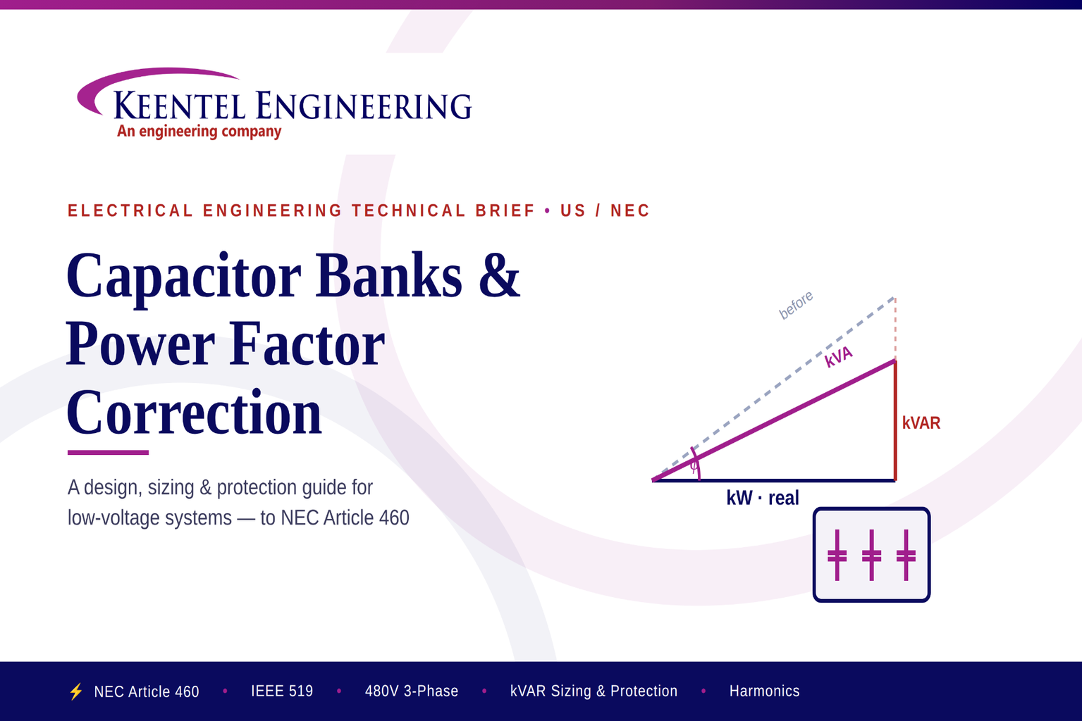
Capacitor Banks & Power Factor Correction A Design, Sizing & Protection Guide for Low-Voltage Systems (US / NEC)
Jul 29, 2026 | Blog
Power factor correction is one of the highest-return, lowest-risk upgrades available on an industrial or commercial electrical system. Correctly sized and protected capacitor banks cut utility demand and reactive-energy charges, free up transformer and feeder capacity, reduce I²R losses, and firm up voltage at the load. This brief walks through the engineering: the reactive-power math, a fully worked 480 V example, conductor and overcurrent sizing to NEC Article 460, harmonic considerations, installation practice, an FAQ, and three anonymized field case studies.
1. Why Power Factor Matters
Every inductive load — motors, transformers, fluorescent and LED driver ballasts, induction furnaces, welders, variable-frequency drives — draws two kinds of current. Real (working) power, measured in kW, does the useful work. Reactive power, measured in kVAR, magnetizes iron and establishes the fields those loads need but performs no net work. The vector sum is apparent power in kVA. Power factor (PF) is simply the ratio of real to apparent power, PF = kW ÷ kVA = cos φ.
A facility running at 0.80 PF is drawing 25% more current than the same real load would require at unity. That surplus current is carried by every conductor, breaker, and transformer between the load and the utility service — and much of it shows up on the bill. A shunt capacitor bank supplies the reactive current locally, so it never has to travel the distribution system.
The four returns on correction
- Lower utility charges. Most commercial/industrial tariffs bill demand in kW or kVA and add a power-factor penalty (or a reactive-energy / kVARh charge) when PF falls below a threshold — commonly 0.90 or 0.95. Correcting PF removes the penalty and can reduce billed kVA demand.
- Released system capacity. Lower current frees headroom in transformers and feeders. Raising PF from 0.80 to 0.95 releases roughly 15–20% of transformer kVA — often deferring a service upgrade.
- Reduced losses. Conductor and transformer losses scale with I². Cutting current cuts I²R heating in cables, bus, and windings, improving efficiency and thermal margin.
- Improved voltage profile. Reactive current causes voltage drop along feeders. Local compensation lifts voltage at the load, which helps motor torque and reduces nuisance dropout.
Engineer's note — what correction does NOT fix
Shunt capacitors correct
displacement power factor (the fundamental-frequency phase shift). They do not correct
distortion power factor caused by harmonic current from nonlinear loads. On a harmonic-rich system, bare capacitors can actually make things worse by resonating with source inductance — which is why detuned reactors and harmonic studies enter the picture (Section 6).
2. What a Capacitor Bank Is
A capacitor bank is a group of power capacitors connected in parallel with the load to supply leading reactive power (kVAR), offsetting the lagging reactive power of inductive equipment. Banks are built as fixed or switched (automatic) assemblies and typically installed at the main distribution board (MDB), a sub-distribution board (SDB / MCC), or directly at a large motor.
Compensation strategies
| Type | Where applied | Best for | Trade-off |
|---|---|---|---|
| Fixed (individual) | At the motor / load terminals | Large, steady loads run near-continuously | Over-correction if the load is switched off; risk of self-excitation on motors |
| Fixed (group) | At a bus or MCC | Several loads with a stable aggregate demand | No response to load variation |
| Automatic (APFC) | At the MDB / SDB | Variable loads; keeps PF in a target band | More hardware — controller, contactors/thyristors, steps |
| Detuned (reactor-connected) | MDB / SDB with nonlinear loads | Systems with VFDs, rectifiers, UPS | Larger footprint; slightly higher cost |
| Active / hybrid | MDB, harmonic-heavy plants | Fast-changing loads + harmonic mitigation | Highest cost; power-electronics based |
3. The Core Calculation
The required capacitor rating to move a load from an initial power factor to a target is:
QC = P × ( tan φ1 − tan φ2 )
where:
- QC = required capacitor rating (kVAR)
- P = real (active) power of the load (kW)
- φ1 = initial power-factor angle, φ1 = cos⁻¹(PFinitial)
- φ2 = target power-factor angle, φ2 = cos⁻¹(PFtarget)
Reference: angle and tangent by power factor
| Power factor (cos φ) | Angle φ | tan φ |
|---|---|---|
| 0.70 | 45.6° | 1.020 |
| 0.80 | 36.9° | 0.750 |
| 0.85 | 31.8° | 0.620 |
| 0.90 | 25.8° | 0.484 |
| 0.95 | 18.2° | 0.329 |
| 0.98 | 11.5° | 0.203 |
| 1.00 | 0.0° | 0.000 |
Read the tangent for the initial and target PF straight from the table, subtract, and multiply by the real load in kW. Two cautions: never target unity (1.0) on an automatic system — it risks over-correction and a leading power factor that can raise voltage and trip protection; 0.95–0.98 is the practical aim. And size against the real measured kW and PF (from a power-quality logger), not nameplate — nameplate almost always overstates demand.
4. Worked Example — 480 V, 3-Phase System
This mirrors a typical US low-voltage industrial service. All protection sizing follows NEC Article 460.
Given
| Parameter | Value |
|---|---|
| Real load, P | 200 kW |
| Existing power factor | 0.80 (lagging) |
| Target power factor | 0.95 |
| System | 480 V, 3-phase, 60 Hz |
Step 1 — Required kVAR
φ1 = cos⁻¹(0.80) = 36.9° → tan φ1 = 0.750
φ2 = cos⁻¹(0.95) = 18.2° → tan φ2 = 0.329
QC = 200 × (0.750 − 0.329) = 200 × 0.421 = 84.3 kVAR
Select the next standard bank size: 90 kVAR. Sizing protection to the selected (installed) rating rather than the raw calculated value is the conservative, correct approach — the capacitors, and everything protecting them, must handle the full installed kVAR.
Step 2 — Rated capacitor current
IC = ( QC × 1000 ) ÷ ( √3 × V )
IC = (90 × 1000) ÷ (1.732 × 480) = 90,000 ÷ 831.4 = 108.3 A
Step 3 — Conductor sizing [NEC 460.8(A)]
Capacitor-circuit conductor ampacity must be at least 135% of the rated capacitor current:
Minimum ampacity = 1.35 × 108.3 A = 146.2 A
From NEC Table 310.16 (75 °C copper), 2/0 AWG Cu is rated 175 A — it satisfies the 135% rule and coordinates with the 175 A overcurrent device selected in Step 4. (1/0 AWG at 150 A meets 135% alone but does not coordinate with a 175 A device.) Apply ambient and conduit-fill correction/adjustment factors per 310.15 before finalizing, and check voltage drop on long runs.
Selected conductor
2/0 AWG copper (75 °C), ~146 A minimum requirement met at 175 A rating.
Step 4 — Overcurrent device [NEC 460.8(B)]
The NEC requires an overcurrent device in each ungrounded conductor, rated “as low as practicable.” Manufacturer practice for dual-element, current-limiting fuses is 150–175% of rated capacitor current to ride through energization inrush without nuisance operation:
Range = 1.50 to 1.75 × 108.3 A = 162 A to 190 A
Select standard device: 175 A (fused disconnect or 3-pole circuit breaker)
Step 5 — Disconnecting means [NEC 460.8(C)]
A disconnecting means is required in each ungrounded conductor, rated at least 135% of the rated capacitor current (146 A) → a 175 A disconnect satisfies this and matches the OCPD.
Summary of the design
| Quantity | Result | Basis |
|---|---|---|
| Required kVAR | 84.3 → select 90 kVAR | Qc = P(tan φ1 − tan φ2) |
| Rated capacitor current | 108.3 A | Qc / (√3 · V) |
| Conductor | 2/0 AWG Cu (75 °C) | 2/0 AWG Cu (75 °C) |
| Overcurrent device | 175 A | 150–175% Ic — NEC 460.8(B) |
| Disconnecting means | 175 A | ≥135% Ic — NEC 460.8(C) |
Verify before you build
These figures are a design starting point. Confirm conductor ampacity against the governing NEC cycle and the actual installation conditions (ambient, grouping, termination temperature rating), verify device interrupting rating (AIC) against the available fault current, and confirm the selected capacitor step ratings, discharge resistors, and enclosure listing. On any system with appreciable nonlinear load, complete a harmonic study before committing to a bare (undetuned) bank.
5. Conductor, Overcurrent & Disconnect Rules — NEC Article 460
Article 460 governs capacitors rated 1000 V nominal and below (Part I). The essentials every capacitor-bank design must satisfy:
| Code | Requirement |
|---|---|
| 460.6 | Stored charge must drain to ≤50 V within 1 minute of de-energization. A manual means of connecting the discharge circuit is prohibited — discharge must be automatic. |
| 460.8(A) | Conductor ampacity ≥135% of rated capacitor current (and ≥1/3 the motor-circuit ampacity where tapped to a motor circuit). |
| 460.8(B) | An overcurrent device in each ungrounded conductor, rating/setting “as low as practicable.” (Common practice: dual-element fuses 150–175%; fast-acting non-time-delay 250–300% of Ic.) |
| 460.8(C) | A disconnecting means in each ungrounded conductor, rated ≥135% of rated capacitor current. May be the OCPD itself. |
| 460.9 | Where connected to a motor, the capacitor kVAR must not exceed the value needed to raise the no-load PF to unity (limits over-excitation). |
| 460.10 | Capacitor cases must be bonded to the equipment grounding conductor. |
Beyond the NEC, IEEE Std 18 defines capacitor ratings and durability (capacitors must withstand 135% of rated kVAR and defined over-voltage/over-current limits), and IEEE Std 1036 gives application guidance for shunt banks. UL 810 lists the capacitors themselves; UL 508A covers the assembled panel.
6. Harmonics, Resonance & Detuned Reactors
Capacitive reactance falls with frequency while the source (transformer) inductive reactance rises with frequency. At some frequency they are equal — parallel resonance. If that resonant frequency lands near a harmonic the plant produces (the 5th at 300 Hz and 7th at 420 Hz are the usual offenders from 6-pulse drives and rectifiers), harmonic currents are amplified, capacitors overheat and fail early, fuses blow, and voltage distortion climbs.
- Screen first. If nonlinear load (VFDs, rectifiers, UPS, induction heating) exceeds roughly 15–20% of the bank/transformer rating, treat the system as harmonic-rich and study it before applying bare capacitors.
- Detune the bank. A series reactor tuned below the lowest significant harmonic (commonly 7% reactor → ~189 Hz, or 14% → ~134 Hz for the 3rd) shifts the resonant point below the 5th harmonic so the branch is inductive at all harmonic frequencies — no amplification, and the branch provides mild filtering.
- Filter or go active where needed. Tuned passive filters or active harmonic filters address distortion directly where limits in IEEE Std 519 must be met at the point of common coupling.
Rule of thumb
Bare capacitors + significant drive load = a resonance question waiting to be answered. When in doubt, log the current spectrum and model the bank against the source impedance before energizing. Retrofitting reactors after a failure is far costlier than specifying them up front.
7. Installation & Good-Practice Checklist
- Locate close to the load center. Install at the MDB, MCC, or large-motor terminals so the corrected current path is as short as possible and losses are minimized.
- Size protection ≥135% of capacitor current per NEC 460.8, and coordinate conductor, OCPD, and disconnect ratings with one another.
- Confirm discharge provisions. Automatic discharge to ≤50 V within one minute (NEC 460.6); verify resistors/reactors are integral to each step.
- Provide ventilation and thermal margin. Capacitors are temperature-sensitive; respect the enclosure ambient rating and provide airflow.
- Bond and ground. Bond all cases to the EGC (NEC 460.10); follow the grounding scheme of the serving board.
- Add detuned reactors where harmonics are significant and verify against IEEE 519 at the point of common coupling.
- Verify interrupting rating (AIC). The disconnect/OCPD must exceed available fault current at the point of installation.
- Label and provide access. Clear identification, step ratings, and working clearance for operation and maintenance.
- Commission with data. Measure PF before and after, verify step switching, and log for the O&M record.
Common mistakes we see
| Mistake | Consequence | Fix |
|---|---|---|
| Sizing from nameplate, not measured load | Over- or under-correction; wasted kVAR | Log real kW / PF with a PQ meter first |
| Targeting unity (1.0) PF automatically | Leading PF, over-voltage, relay trips | Target 0.95–0.98 band |
| Bare bank on a drive-heavy plant | Resonance, capacitor/fuse failures | Harmonic study + detuned reactors |
| Undersized conductors / OCPD | Nuisance trips, overheating, code violation | Apply the 135% rule (NEC 460.8) |
| No/weak discharge path | Shock hazard, switching transients | Automatic discharge per 460.6 |
| AIC below available fault current | Device fails to clear a fault safely | Confirm short-circuit study |
8. Field Case Studies
Three representative projects, anonymized. Client names and locations are withheld; figures are rounded and illustrative of the engineering approach and typical outcomes.
CASE STUDY 1 — Metal Fabrication Plant — Utility Penalty Elimination
| Parameter | Detail |
|---|---|
| Facility type | Heavy metal fabrication, multi-shift |
| Service | 480 V, 3-phase |
| Problem | Measured PF 0.79 lagging; monthly utility power-factor penalty and high billed kVA demand |
| Dominant loads | Induction motors, welders, overhead cranes |
| Solution | Automatic (APFC) capacitor bank at the MDB, contactor-switched steps |
| Installed rating | Sized from a 30-day PQ log; multi-step bank targeting 0.96–0.97 |
| Protection | Conductors and devices per NEC 460.8 (135% rule) |
A 30-day power-quality log established a real average load and a lagging PF of 0.79 — well under the utility's 0.90 threshold, generating a recurring penalty and inflated kVA demand charges. Sizing from the logged data (not nameplate) produced a multi-step automatic bank targeting a 0.96–0.97 band, installed at the main distribution board with steps switched by a PF controller.
Outcome: the power-factor penalty was eliminated and billed demand dropped, with a simple payback well inside the range typical for penalty-removal projects (roughly 1–2 years). Freed transformer headroom also deferred a planned service upgrade. Because welders and cranes cycle hard, contactor step timing and a small hysteresis band were tuned during commissioning to avoid hunting.
CASE STUDY 2 — Water / Wastewater Pumping Station — Resonance Remediation
| Parameter | Detail |
|---|---|
| Facility type | Municipal-style pumping station |
| Service | 480 V, 3-phase, VFD-driven pumps |
| Problem | An existing bare capacitor bank suffered repeated capacitor and fuse failures |
| Dominant loads | 6-pulse VFDs on large pumps (high 5th/7th harmonic content) |
| Solution | Replace bare bank with a detuned (7% reactor) bank after a harmonic study |
| Standards | NEC 460 · IEEE 519 verification at the PCC |
| Protection | Re-rated conductors/OCPD to NEC 460.8 |
The station had installed a conventional (undetuned) capacitor bank to correct PF on VFD-driven pumps. Within months it was failing capacitors and clearing fuses repeatedly. A harmonic survey found the bank resonating near the 5th harmonic against the source impedance, amplifying harmonic current through the capacitors.
The remedy was a detuned bank with 7% series reactors, shifting the branch resonance below the 5th harmonic so the branch is inductive at every harmonic frequency. Post-installation measurements confirmed harmonic current amplification was gone and voltage distortion sat within IEEE 519 guidance at the point of common coupling.
Outcome: capacitor and fuse failures stopped, power factor was corrected reliably, and the plant retained the loss and capacity benefits without the resonance risk. The lesson — screen for nonlinear load and study before applying bare capacitors on drive-heavy systems.
CASE STUDY 3 Commercial Campus / Data-Adjacent Facility Capacity Release
| Parameter | Detail |
|---|---|
| Facility type | Mixed commercial campus with mechanical plant |
| Service | 480 V, 3-phase, multiple sub-boards |
| Problem | Chillers, AHUs, pumps, lighting |
| Solution | Distributed automatic banks at the sub-boards feeding mechanical loads |
| Installed rating | Sized to lift PF to ~0.97 across metered feeders Sized to lift PF to ~0.97 across metered feeders |
| Protection | NEC 460.8 sizing; bonded and discharge-verified NEC 460.8 sizing; bonded and discharge-verified |
A growing campus was nearing the thermal limit of its service transformer, and a straight capacity upgrade carried a heavy cost and outage. Metering showed an aggregate PF around 0.84 across the mechanical feeders, meaning roughly a fifth of the transformer's current was reactive.
Rather than upsize the transformer, automatic capacitor banks were placed at the sub-boards feeding the chiller and pump loads, correcting PF to about 0.97 at the source of the reactive demand. Lowering the reactive component cut the current the transformer had to carry and released enough capacity to accommodate near-term growth.
Outcome: the transformer upgrade was deferred, feeder losses dropped, and the voltage profile at the mechanical rooms improved. Distributing the correction (rather than one central bank) captured more of the loss benefit and kept each bank close to the loads it served.
9. Standards & Reference Checklist
| Standard | Scope |
|---|---|
| NFPA 70 (NEC) Article 460 | Installation of capacitors: conductors, overcurrent, disconnect, discharge, grounding |
| IEEE Std 18 | Shunt power capacitors — ratings and durability requirements |
| IEEE Std 1036 | Guide for application of shunt power capacitors |
| IEEE Std 519 | Recommended practice for harmonic control in electric power systems |
| UL 810 | Listing standard for capacitors |
| UL 508A | Industrial control panels (assembled APFC/capacitor panels) |
| NEMA / utility tariff | Enclosure ratings; governing power-factor / demand rate schedule |
Design Smarter. Build Better.
Correctly sized and protected capacitor banks are among the most cost-effective upgrades on an electrical system — provided the reactive-power math, NEC Article 460 protection, and harmonic behavior are handled together rather than in isolation. The worked example and case studies above show the same discipline every time: measure the real load, size to the installed kVAR, protect to the 135% rule, and study for harmonics before energizing.
Work with Keentel Engineering
Keentel Engineering provides electrical and power engineering across MEP, distribution, and renewable/transmission projects. Our team can measure your system, model harmonics, size and specify capacitor banks to NEC Article 460 and IEEE guidance, and coordinate protection end to end — so the correction you install performs and lasts.
Frequently asked questions
Q1. What power factor should I target?
For automatic systems, aim for a 0.95–0.98 band. It clears virtually all utility penalties and releases most of the available capacity without risking a leading power factor. Avoid targeting unity (1.0): a small load swing then pushes the system capacitive, which raises voltage and can trip protection.
Q2. How much can power factor correction save?
It depends on the tariff. If the utility applies a PF penalty or bills on kVA demand, removing a 0.80 PF penalty can trim a meaningful percentage off the demand portion of the bill, and payback is frequently under 1–3 years. The only way to size the saving is to read the actual rate schedule and a month of interval data.
Q3. Fixed or automatic bank — which do I need?
Fixed banks suit large, steady loads that run continuously (a single big motor or a base transformer load). Automatic (APFC) banks suit variable loads because they switch kVAR steps in and out to hold PF in a target band. Most commercial/industrial facilities with changing load use automatic panels.
Q4. Can I connect capacitors directly at a motor?
Yes, for individual correction — but keep the kVAR at or below the motor's no-load magnetizing kVAR (the intent of NEC 460.9) to avoid self-excitation and over-voltage when the motor coasts down. Never switch the capacitor with the motor if it can leave the capacitor energized by a spinning motor. For VFD-fed motors, do not connect capacitors on the drive output.
Q5. Why did my capacitors fail early?
The most common cause is harmonic resonance. Capacitors present a low impedance to harmonic currents; if the bank resonates with the source near the 5th or 7th harmonic, the resulting over-current cooks the units. Over-voltage, high ambient temperature, and frequent switching transients also shorten life. A harmonic study and detuned reactors usually solve it.
Q6. What is a detuned reactor and when do I need one?
It's a series inductor ahead of each capacitor step, sized (commonly 7%) so the LC branch resonates below the lowest significant harmonic. This makes the branch inductive at all harmonic frequencies, preventing amplification and providing light filtering. Specify detuned banks when nonlinear load exceeds ~15–20% of the bank or transformer rating.
Q7. How do I size the cable and breaker?
Per NEC 460.8: conductor ampacity at least 135% of rated capacitor current [460.8(A)]; an overcurrent device in each ungrounded conductor sized as low as practicable — typically 150–175% of capacitor current for dual-element fuses [460.8(B)]; and a disconnecting means rated at least 135% [460.8(C)]. Section 4 works a full 480 V example.
Q8. Does correction help with harmonics?
Not by itself. Shunt capacitors correct displacement (fundamental) power factor, not the distortion caused by harmonics. To improve true power factor on a distorted system you need detuned banks, tuned passive filters, or active harmonic filters — sized to meet IEEE 519 at the point of common coupling.
Q9. Where should the bank be installed?
As close to the reactive load as practical — the MDB, an MCC/sub-board feeding the inductive loads, or the motor. Closer placement shortens the path carrying the corrected current and captures more of the loss and capacity benefit.
Q10. What standards govern capacitor banks in the US?
NFPA 70 (NEC) Article 460 for installation, conductors, overcurrent, disconnect, discharge, and grounding; IEEE Std 18 for capacitor ratings and durability; IEEE Std 1036 for application; IEEE Std 519 for harmonic limits; UL 810 for the capacitors and UL 508A for the assembled panel. Always design to the code cycle actually adopted in the jurisdiction.
Q11. How often should a bank be maintained?
Periodically inspect for bulged cans, check step switching and controller setpoints, verify contactor/fuse condition, confirm discharge function, and thermally scan connections. Capacitance drift and failed steps quietly erode correction, so an annual PF check against the commissioning baseline is worthwhile.
Closing thoughts
The choice between an on-load and an off-circuit tap changer looks binary, but the engineering behind it is a genuine optimization: matching the device's capability, cost, and maintenance burden to the duty it will actually see over a forty-year life. Get it right and voltage stays in band, assets age gracefully, and outages stay planned. Get it wrong — an OCTC where regulation was needed, an OLTC left unmonitored until it fails, a de-energized changer operated live — and the transformer becomes the weak link in the system. The device is small relative to the transformer; the consequences of specifying, operating, or maintaining it poorly are not.
Keentel Engineering helps utilities and industrial operators make that call with confidence — from selection and specification through condition assessment, monitoring strategy, and failure investigation — always as an independent adviser working from the standards and your own data. If you are specifying a new transformer, worried about an aging tap changer, or facing new voltage volatility on your network, we would welcome the conversation.
Keentel Engineering
Independent electrical engineering consultancy — transformer, tap-changer, and power-system advisory.
Selected standards and references
IEEE C57.131 — Standard Requirements and Test Methods for Tap-Changers.
IEC/IEEE 60214-1 — Tap-changers, Part 1: Performance requirements and test methods.
IEC/IEEE 60214-2 — Tap-changers, Part 2: Application guidelines.
IEEE C57.12.00 and IEC 60076 series — Power transformer standards (parent context).

About the Author:
Sandip "Sonny" R. Patel, P.E.
IEEE Senior Member · Founder & CEO, Keentel Engineering
In 1995, Sonny Patel earned his Electrical Engineering degree from the University of Illinois. But degrees don't build legacies — action does.
For three decades, he has worked the power industry from every side of the table: 16 years as a utility engineer at Exelon/Commonwealth Edison; generation leadership across hydroelectric, industrial steam turbine, and a 9 GW renewable fleet; NERC Regional Entity Senior Compliance Engineer and Audit Team Lead, auditing some of the nation's largest utilities; and testing and commissioning lead on equipment up to 765 kV — the very top of the North American grid.Utility. Generator. Regulator. Consultant. Few engineers have seen all four seats. Fewer still have sat in them.
His experience spans nuclear, hydro, conventional generation, renewables, oil and gas, mining — and today's data centers, where he is authoring a three-book series on data center design. He is a Licensed Professional Engineer in six states and a Licensed Electrical Contractor in Florida (Unlimited EC) — he doesn't just design the work; he's qualified to stand behind its execution.Today, as Founder and CEO of Keentel Engineering, Sonny leads a nationwide team of engineers delivering substation design, power system studies, NERC compliance, and commissioning — done right, coast to coast.Three decades. Every side of the table. One standard: accountable engineering.
Services

Let's Discuss Your Project
Let's book a call to discuss your electrical engineering project that we can help you with.
About the Author:
Sandip "Sonny" R. Patel, P.E.
IEEE Senior Member · Founder & CEO, Keentel Engineering
In 1995, Sonny Patel earned his Electrical Engineering degree from the University of Illinois. But degrees don't build legacies — action does.
For three decades, he has worked the power industry from every side of the table: 16 years as a utility engineer at Exelon/Commonwealth Edison; generation leadership across hydroelectric, industrial steam turbine, and a 9 GW renewable fleet; NERC Regional Entity Senior Compliance Engineer and Audit Team Lead, auditing some of the nation's largest utilities; and testing and commissioning lead on equipment up to 765 kV — the very top of the North American grid.
Utility. Generator. Regulator. Consultant. Few engineers have seen all four seats. Fewer still have sat in them.
His experience spans nuclear, hydro, conventional generation, renewables, oil and gas, mining — and today's data centers, where he is authoring a three-book series on data center design. He is a Licensed Professional Engineer in six states and a Licensed Electrical Contractor in Florida (Unlimited EC) — he doesn't just design the work; he's qualified to stand behind its execution.
Today, as Founder and CEO of Keentel Engineering, Sonny leads a nationwide team of engineers delivering substation design, power system studies, NERC compliance, and commissioning — done right, coast to coast.Three decades. Every side of the table. One standard: accountable engineering.
Leave a Comment
Thank you for contacting us.
We will get back to you as soon as possible.
We will get back to you as soon as possible.
Oops, there was an error sending your message.
Please try again later.
Please try again later.
Related Posts
By SANDIP R PATEL
•
September 9, 2026
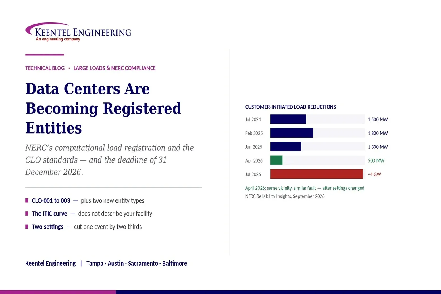
Learn how NERC computational load registration impacts data centers, CLO standards, ride-through requirements, modeling, and grid reliability compliance.
By SANDIP R PATEL
•
September 7, 2026
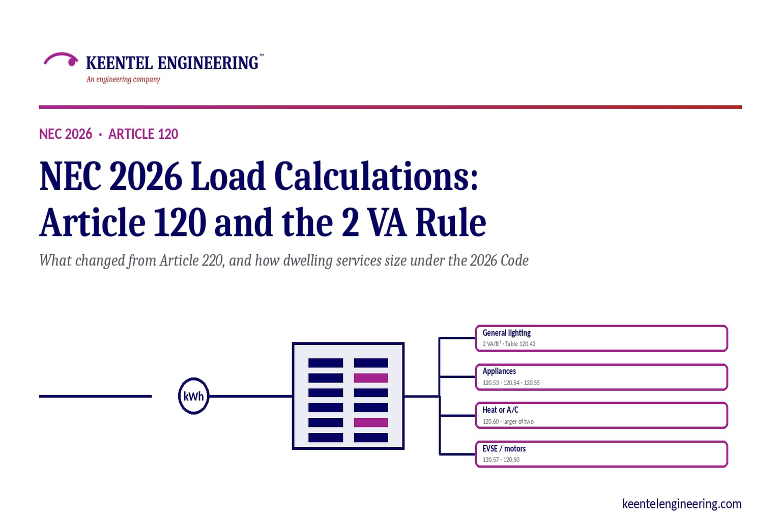
Learn NEC 2026 load calculations, Article 120 changes, the 2 VA rule, EV charging requirements, service sizing, and dwelling calculation methods.
By SANDIP R PATEL
•
September 7, 2026
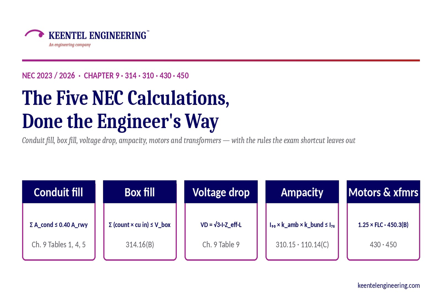
Learn five essential NEC calculations covering conduit fill, voltage drop, ampacity, motor circuits, and transformer protection with engineering examples.
By SANDIP R PATEL
•
September 7, 2026
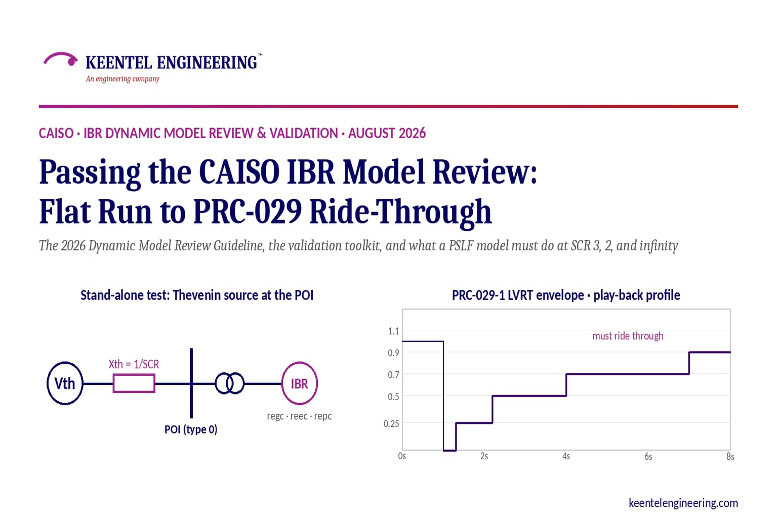
Learn how CAISO reviews IBR models using PSLF validation, PRC-029-1 ride-through requirements, WECC models, and inverter resource compliance testing.
By SANDIP R PATEL
•
September 7, 2026
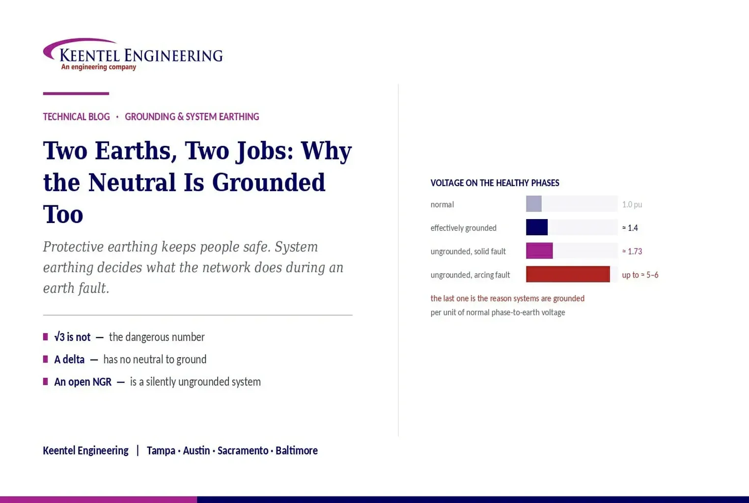
Understand system earthing and protective earthing, neutral grounding methods, effective grounding, ground grids, and insulation coordination for power systems
By SANDIP R PATEL
•
September 6, 2026
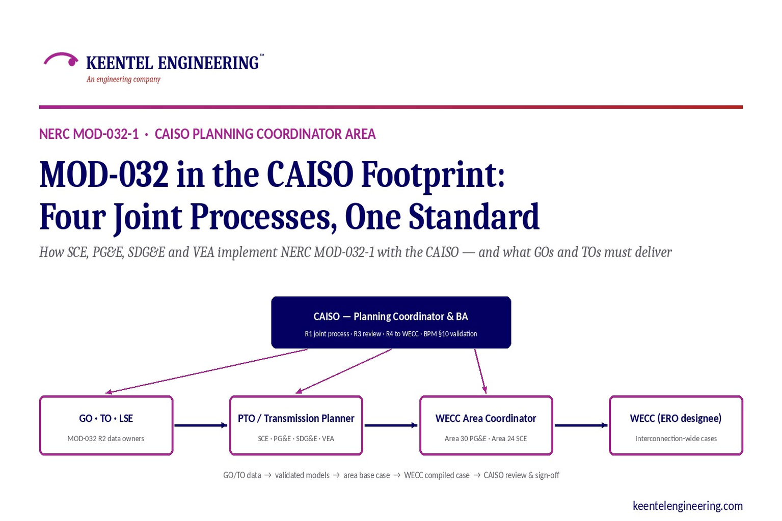
Learn how NERC MOD-032-1 applies across CAISO, SCE, PG&E, VEA and SDG&E, including generator data, PSLF models, EMT requirements and WECC submissions.
By SANDIP R PATEL
•
September 6, 2026
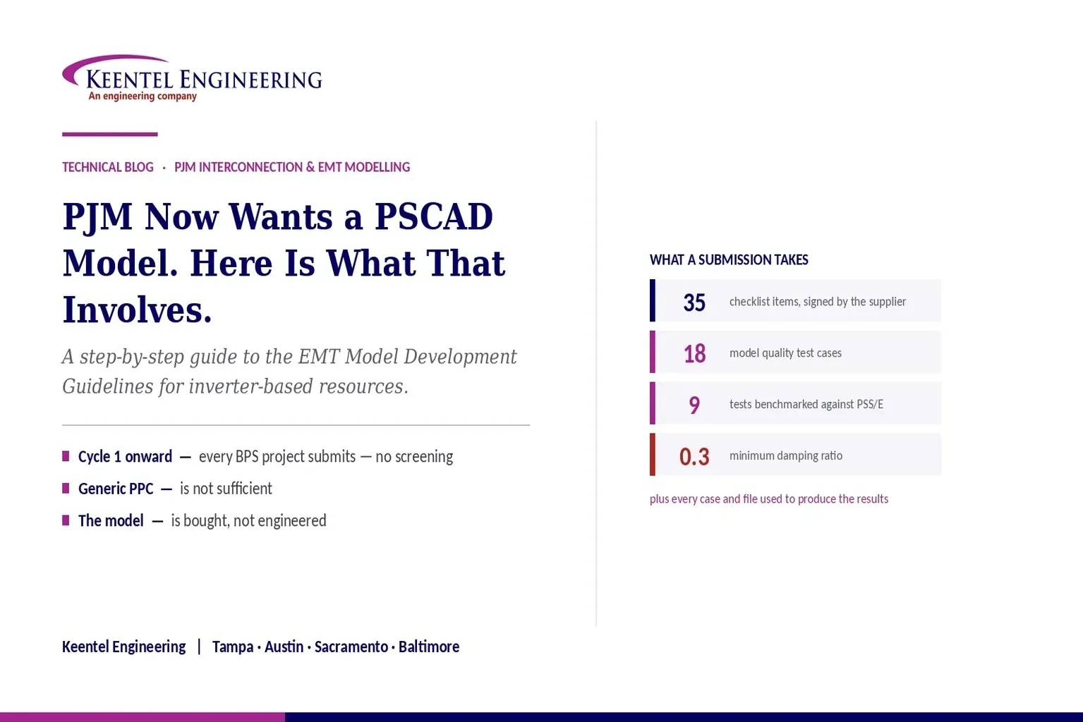
Learn PJM PSCAD model requirements for inverter-based resources, EMT testing, PSS/E benchmarking, ride-through studies, and compliance submissions
By SANDIP R PATEL
•
September 6, 2026
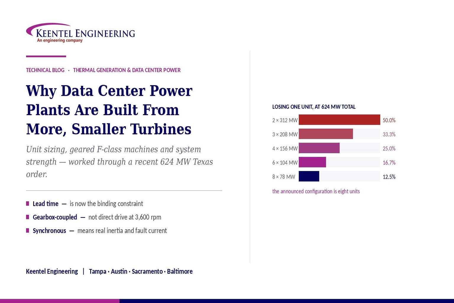
Learn why data center power plants use multiple smaller gas turbines, covering 624 MW capacity, redundancy, grid connection, system strength, and engineering.
By SANDIP R PATEL
•
September 5, 2026
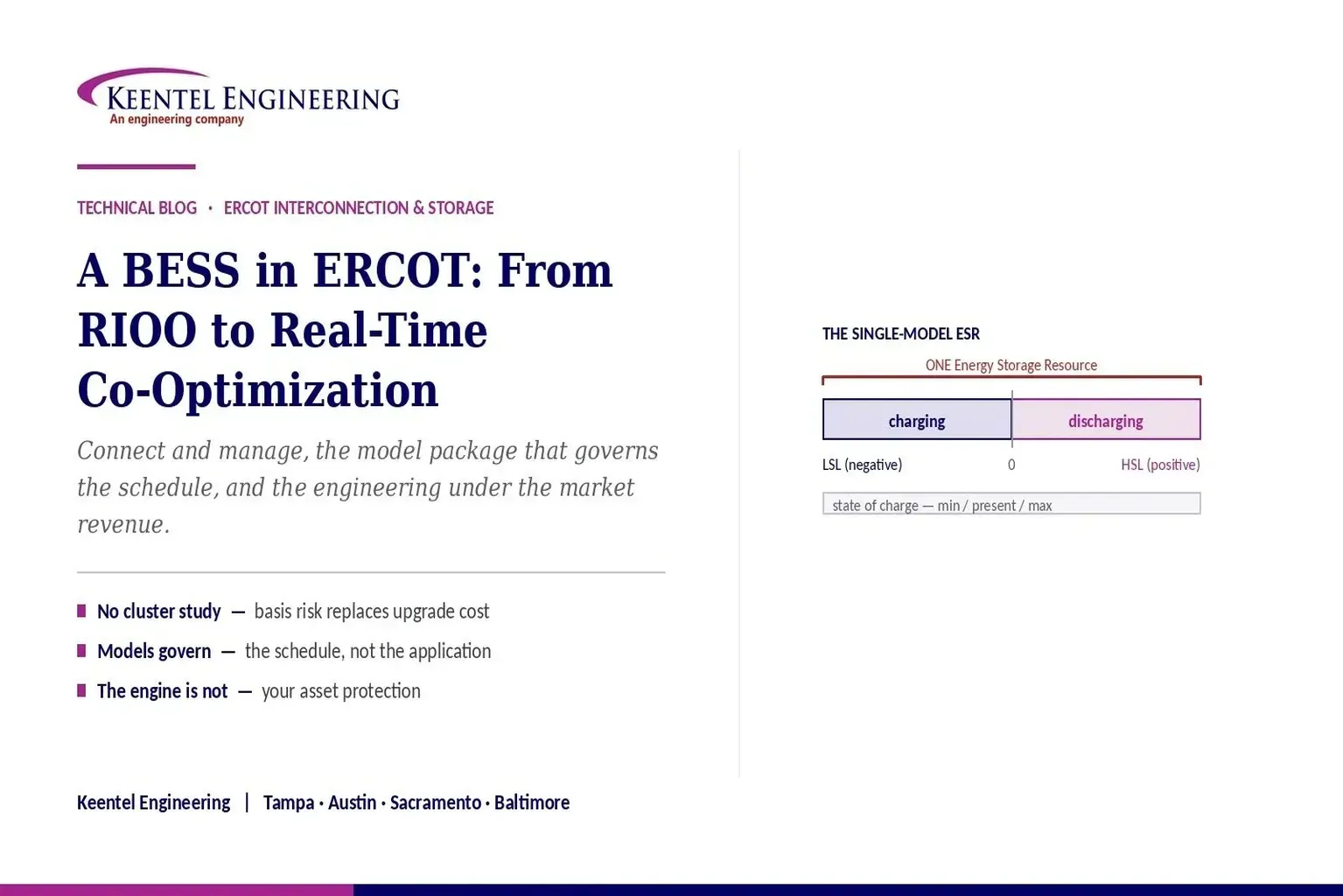
Understand ERCOT BESS interconnection requirements, including model packages, EMT studies, ride-through compliance, telemetry, and real-time co-optimization.





