A Coordinated Electric System Interconnection Review—the utility’s deep-dive on technical and cost impacts of your project.
Challenge: Frequent false tripping using conventional electromechanical relays
Solution: SEL-487E integration with multi-terminal differential protection and dynamic inrush restraint
Result: 90% reduction in false trips, saving over $250,000 in downtime
ERCOT enforces all of the above through simulation, which means your model is your compliance case. The bar is now high:
- Whole-facility scope. The model must represent everything the IT load, the UPS and power conversion, the cooling plant, the protection and control systems in formats compatible with ERCOT's study platforms (PSS/E, PSCAD, TSAT).
- Real control loops, not approximations. Generic textbook representations are unacceptable. The model must capture the actual inner control behavior of your power electronics.
- Hardware-validated converter models. For electronic loads, the PSCAD model must be benchmarked against actual hardware testing including voltage ride-through and subsynchronous response. A model assembled from standard PSCAD library blocks fails by definition, because a generic block has never been tested against your vendor's hardware. The good news: validation is a hardware-type test, so results for a given converter product are reusable across every facility that uses it.
- Format migration. Facilities that previously submitted the older composite load model (CMLD) format must transition to EPRI's PERC1 format.
- Three checkpoints. Models are reviewed before the stability study begins (no model, no study), before each quarterly stability assessment, and for electronic loads one final time before energization, when you must submit as-built models with a documented comparison against the previously studied data and a sworn attestation that the model matches actual field settings. ERCOT's review takes 10 business days, extendable by 20 put it on your critical path.
- A living obligation. Change your technology, controls, or relay settings in a way that affects ride-through including converting a crypto mining site to an AI data center — and you've triggered a new interconnection study, even if your megawatts don't change.
| Parameter | Detail |
|---|---|
| System | 230 kV / 138 kV transmission corridors, wind and wet-snow icing exposure |
| Data basis | 15 years of minute-resolution forced-outage records + regional weather observations |
| Core methods | Event grouping, MVA performance curves, time-to-95%-restore, area outage rate curves, fragility modeling, rerun-history benefits, exceedance and log-domain risk metrics |
| Headline result | ≈85% of maximum resilience benefit at 60% of original capital; worst-event restoration window cut from 11 days to 5 in rerun-history terms |
| Decision supported | Capital portfolio selection; resilience plan filing; post-investment verification framework |
| System / Topic | Governing Standard(s) | What It Controls |
|---|---|---|
| Overall plant electrical distribution | IEEE 141 (Red Book); IEEE 666 | Distribution architecture, voltage selection, design of generating station auxiliary service systems |
| Power system studies | IEEE 399 (Brown Book); IEEE 551 | Load flow, symmetrical/asymmetrical short circuit, motor starting methodologies down to the lowest LV panelboard |
| Protection & coordination | IEEE 242 (Buff Book); IEEE 3004.5; IEEE C37 series | Generator relaying (21, 59N, 87G), time-current coordination, selective clearing between LV and MV tiers |
| GSU / UAT / SST transformers | IEEE C57.12.00 and C57 family | Transformer ratings, impedance, testing, loading |
| HV switchyard breakers | IEEE C37.06 | AC high-voltage circuit breaker preferred ratings |
| MV switchgear (13.8 kV) | IEEE C37.20.2; IEEE C37.20.7 | Metal-clad construction, compartmentalization, vacuum breakers; arc-resistant design with plenum venting |
| MV cable | UL 1072; ICEA S-93-639 (NEMA WC 74) | Type MV-105 shielded cable, 133% insulation level for HRG systems |
| LV switchgear (480 V) | IEEE C37.13; UL 1558 | Metal-enclosed LV power circuit breaker switchgear to 635 V, draw-out ACBs with electronic trip units |
| Motor control centers | UL 845; NEMA ICS 18 | LV-MCC construction, MCCB/MCP protection for motors under ~200 HP |
| Motors | NEMA MG-1 | Motor performance, starting characteristics, service factors |
| DC & battery systems | IEEE 485; IEEE 946 | Lead-acid battery sizing (125/250 VDC), DC auxiliary system design |
| Grounding | IEEE 80; IEEE 142 (Green Book) | Ground grid step/touch potential limits; system grounding including high-resistance grounding |
| Lightning protection | IEEE 998 | Direct-stroke shielding of switchyard and outdoor generator structures |
| Arc flash & electrical safety | IEEE 1584; NFPA 70E | Incident energy calculation; worker safety boundaries and PPE |
| Fire protection | NFPA 850 | Fire protection and risk management for combustion turbine generating plants |
| Installation code | NEC (NFPA 70); NESC | Wiring methods inside the plant fence; overhead/outdoor clearances at the switchyard |
| Interconnection & compliance | FERC LGIP; NERC MOD-025/026/027, PRC-019/024/029, FAC-008 | Interconnection process, model validation, protection/ride-through coordination, facility ratings |
| IFC / Construction Deliverable | Purpose |
|---|---|
| Stamped IFC packages | Legal basis for construction; P.E. responsible charge |
| Final relay settings & TCCs | Protection as-installed matches the coordination study |
| Calculation archive | Owner records; NERC audit evidence trail |
| Commissioning procedures | Safe, sequenced energization; MOD field testing |
| Construction support | RFIs, field changes, FAT/SAT witness |
| As-builts & model handoff | Operating baseline; future study currency |
| Metric | Outcome |
|---|---|
| Defects found pre-occupancy | Three topology defects and one settings-mismatch family corrected before load migration; the shared-switchboard defect alone would have invalidated the concurrently-maintainable claim on day one |
| IST findings | Fourteen additional discrepancies surfaced under scenario testing (control logic, alarm mapping, one generator sequencing fault) — all closed before handover instead of during operations |
| Black-building test | Passed on second execution; the first attempt exposed the generator sequencing fault under true block load, exactly the failure the compressed plan would never have found |
| Handover quality | Operations team certified on the actual failure scenarios; corrected EOPs and settings documentation delivered as controlled documents |
| Business outcome | Occupancy proceeded three weeks behind the original date — against an independent estimate that the uncorrected sequencing fault carried a high probability of a full facility outage within the first year |
Part 2 — Frequently Asked Questions: Large Load Interconnection
| Contact | Details |
|---|---|
| Headquarters | 400 N Ashley Dr STE 2600, Tampa, FL 33602 |
| Phone | (813) 389-7871 |
| contact@keentelengineering.com | |
| Florida Firm Registration | No. 36853 |
| Additional Offices | Austin, TX • Sacramento, CA • Baltimore, MD |
| Who | Acronym | Plain-English Role |
|---|---|---|
| ERCOT | — | The grid's air traffic controller. It doesn't own power lines or plants; it directs the flow of electricity across most of Texas and referees the admission process for new generators. |
| Interconnecting Entity | IE | You — the developer or owner trying to connect a new plant (or significantly modify an existing one). You file the application and drive the process. |
| Resource Entity | RE | The registered owner/operator of the generator once it becomes an official market participant. Often the same company as the IE, wearing a different hat. |
| Qualified Scheduling Entity | QSE | Your plant's voice on the grid. The QSE handles round-the-clock communications with ERCOT — telemetry, schedules, dispatch instructions. Every generator must have one. |
| Transmission Service Provider | TSP | The utility that owns the wires and substation you'll connect to. The TSP runs your detailed study, builds the connection facilities, and signs your interconnection contract. |
| RIOO-IS | — | ERCOT's online portal where the whole process lives — applications, documents, status tracking, and checklists all flow through it. |
| Who | Acronym | Plain-English Role |
|---|---|---|
| ERCOT | — | The grid's air traffic controller. It doesn't own power lines or plants; it directs the flow of electricity across most of Texas and referees the admission process for new generators. |
| Interconnecting Entity | IE | You — the developer or owner trying to connect a new plant (or significantly modify an existing one). You file the application and drive the process. |
| Resource Entity | RE | The registered owner/operator of the generator once it becomes an official market participant. Often the same company as the IE, wearing a different hat. |
| Qualified Scheduling Entity | QSE | Your plant's voice on the grid. The QSE handles round-the-clock communications with ERCOT — telemetry, schedules, dispatch instructions. Every generator must have one. |
| Transmission Service Provider | TSP | The utility that owns the wires and substation you'll connect to. The TSP runs your detailed study, builds the connection facilities, and signs your interconnection contract. |
| RIOO-IS | — | ERCOT's online portal where the whole process lives — applications, documents, status tracking, and checklists all flow through it. |
| Who | Acronym | Plain-English Role |
|---|---|---|
| ERCOT | — | The grid's air traffic controller. It doesn't own power lines or plants; it directs the flow of electricity across most of Texas and referees the admission process for new generators. |
| Interconnecting Entity | IE | You — the developer or owner trying to connect a new plant (or significantly modify an existing one). You file the application and drive the process. |
| Resource Entity | RE | The registered owner/operator of the generator once it becomes an official market participant. Often the same company as the IE, wearing a different hat. |
| Qualified Scheduling Entity | QSE | Your plant's voice on the grid. The QSE handles round-the-clock communications with ERCOT — telemetry, schedules, dispatch instructions. Every generator must have one. |
| Transmission Service Provider | TSP | The utility that owns the wires and substation you'll connect to. The TSP runs your detailed study, builds the connection facilities, and signs your interconnection contract. |
| RIOO-IS | — | ERCOT's online portal where the whole process lives — applications, documents, status tracking, and checklists all flow through it. |
| Who | Acronym | Plain-English Role |
|---|---|---|
| ERCOT | — | The grid's air traffic controller. It doesn't own power lines or plants; it directs the flow of electricity across most of Texas and referees the admission process for new generators. |
| Interconnecting Entity | IE | You — the developer or owner trying to connect a new plant (or significantly modify an existing one). You file the application and drive the process. |
| Resource Entity | RE | The registered owner/operator of the generator once it becomes an official market participant. Often the same company as the IE, wearing a different hat. |
| Qualified Scheduling Entity | QSE | Your plant's voice on the grid. The QSE handles round-the-clock communications with ERCOT — telemetry, schedules, dispatch instructions. Every generator must have one. |
| Transmission Service Provider | TSP | The utility that owns the wires and substation you'll connect to. The TSP runs your detailed study, builds the connection facilities, and signs your interconnection contract. |
| RIOO-IS | — | ERCOT's online portal where the whole process lives — applications, documents, status tracking, and checklists all flow through it. |
| Who | Acronym | Plain-English Role |
|---|---|---|
| ERCOT | — | The grid's air traffic controller. It doesn't own power lines or plants; it directs the flow of electricity across most of Texas and referees the admission process for new generators. |
| Interconnecting Entity | IE | You — the developer or owner trying to connect a new plant (or significantly modify an existing one). You file the application and drive the process. |
| Resource Entity | RE | The registered owner/operator of the generator once it becomes an official market participant. Often the same company as the IE, wearing a different hat. |
| Qualified Scheduling Entity | QSE | Your plant's voice on the grid. The QSE handles round-the-clock communications with ERCOT — telemetry, schedules, dispatch instructions. Every generator must have one. |
| Transmission Service Provider | TSP | The utility that owns the wires and substation you'll connect to. The TSP runs your detailed study, builds the connection facilities, and signs your interconnection contract. |
| RIOO-IS | — | ERCOT's online portal where the whole process lives — applications, documents, status tracking, and checklists all flow through it. |
| Who | Acronym | Plain-English Role |
|---|---|---|
| ERCOT | — | The grid's air traffic controller. It doesn't own power lines or plants; it directs the flow of electricity across most of Texas and referees the admission process for new generators. |
| Interconnecting Entity | IE | You — the developer or owner trying to connect a new plant (or significantly modify an existing one). You file the application and drive the process. |
| Resource Entity | RE | The registered owner/operator of the generator once it becomes an official market participant. Often the same company as the IE, wearing a different hat. |
| Qualified Scheduling Entity | QSE | Your plant's voice on the grid. The QSE handles round-the-clock communications with ERCOT — telemetry, schedules, dispatch instructions. Every generator must have one. |
| Transmission Service Provider | TSP | The utility that owns the wires and substation you'll connect to. The TSP runs your detailed study, builds the connection facilities, and signs your interconnection contract. |
| RIOO-IS | — | ERCOT's online portal where the whole process lives — applications, documents, status tracking, and checklists all flow through it. |
| Who | Acronym | Plain-English Role |
|---|---|---|
| ERCOT | — | The grid's air traffic controller. It doesn't own power lines or plants; it directs the flow of electricity across most of Texas and referees the admission process for new generators. |
| Interconnecting Entity | IE | You — the developer or owner trying to connect a new plant (or significantly modify an existing one). You file the application and drive the process. |
| Resource Entity | RE | The registered owner/operator of the generator once it becomes an official market participant. Often the same company as the IE, wearing a different hat. |
| Qualified Scheduling Entity | QSE | Your plant's voice on the grid. The QSE handles round-the-clock communications with ERCOT — telemetry, schedules, dispatch instructions. Every generator must have one. |
| Transmission Service Provider | TSP | The utility that owns the wires and substation you'll connect to. The TSP runs your detailed study, builds the connection facilities, and signs your interconnection contract. |
| RIOO-IS | — | ERCOT's online portal where the whole process lives — applications, documents, status tracking, and checklists all flow through it. |
Why LV Earth Fault Current Doesn't Cross to the HV Side: The Engineering Reality Behind Delta-Star Transformers
Jul 27, 2026 | Blog
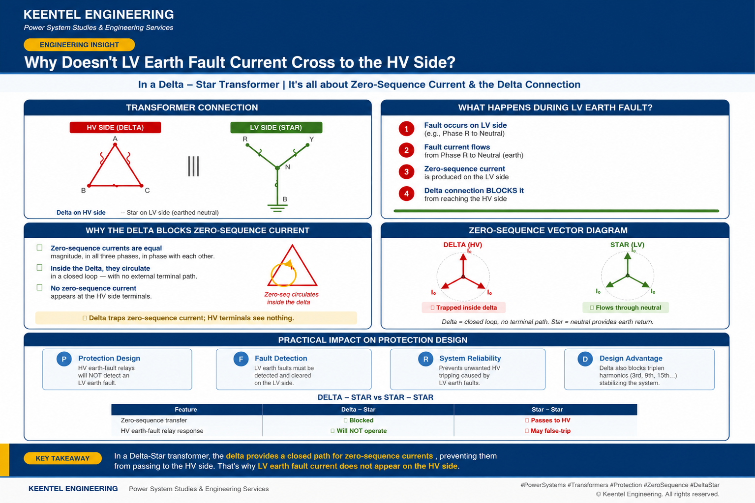
Every day, thousands of Delta-Star transformers across distribution networks silently perform a function that most system operators take for granted: they contain low-voltage earth faults on the LV side, preventing zero-sequence disturbances from propagating upstream to the high-voltage grid. This behaviour is not accidental; it is the direct consequence of a specific winding configuration choice made when the transformer was specified — a choice that has profound implications for protection scheme design, fault detection reliability, and overall system stability.
For asset owners, EPC contractors, and utility planners, understanding this behaviour is not academic. Getting it wrong means specifying protection relays that will never operate, or worse, expecting fault detection that the physics of the transformer will never allow. This article — part of the Keentel Engineering Power System Studies technical series — examines why Delta-Star transformers block zero-sequence current from crossing to the HV side, what this means practically for protection design, and how Keentel Engineering brings this understanding into every substation, industrial plant, and distribution study we deliver.
The Configuration in Question
A Delta-Star (also written Dyn11, Dyn1, or similar depending on vector group) transformer has its high-voltage winding connected in delta and its low-voltage winding connected in star (wye) with the star point brought out and typically earthed. This is by far the most common configuration for distribution transformers worldwide — it appears in HV/MV distribution substations, MV/LV package substations, industrial plant service transformers, and grid-connection transformers for renewable energy plants.
The reason it dominates is not coincidental. The Delta-Star configuration provides four practical benefits simultaneously: it makes a solidly earthed LV neutral available for single-phase loads and earth-fault protection, it blocks triplen harmonic currents (3rd, 9th, 15th) from reaching the HV network, it isolates the HV and LV zero-sequence systems electromagnetically, and it maintains balanced HV line currents even when the LV loads are severely unbalanced. Each of these is a story in itself; the second and third are the focus of this article.
What Actually Happens During an LV Earth Fault
Consider a phase-to-earth fault on the LV side — say, a cable insulation failure on the R phase, or a broken conductor falling to ground. The resulting fault current path is straightforward: fault current flows from the LV R phase, through the fault to earth, back through the earth or the earth return conductor, and returns to the transformer through the earthed star point on the LV neutral. This is a fault confined to the LV side, and it produces a specific type of current known as zero-sequence current.
Zero-Sequence Current The Missing Symmetry
In three-phase system analysis using symmetrical components, any set of unbalanced three-phase currents can be decomposed into three balanced sets: positive-sequence (normal rotation), negative-sequence (reverse rotation), and zero-sequence (three currents equal in magnitude, all in phase, no rotation). Zero-sequence currents are the mathematical fingerprint of any fault involving earth: they cannot exist in a system with no earth connection, and their magnitude directly measures how much current is flowing through the earth path.
During an LV single-phase-to-earth fault on a Delta-Star transformer, the LV star winding carries a substantial zero-sequence current in the faulted phase. The star point provides the neutral path back to the source. So far, everything obeys standard fault current physics.
The Point of No Passage
Now the interesting question: what happens on the HV delta side? A zero-sequence current on the LV star winding attempts to induce a corresponding zero-sequence current on the coupled HV winding — but zero-sequence current in a delta cannot flow into or out of the transformer terminals. It can only circulate around the closed delta loop. This is a topological fact: the delta is a closed triangle with no external neutral, so any set of three equal, in-phase currents at the terminals would violate Kirchhoff's current law (they would have to sum to zero at each node, but they are all equal and in phase, which means they would have to be zero to sum to zero at the delta apex nodes).
The result: the zero-sequence MMF induced on the HV delta winding is balanced by a circulating current inside the delta loop, and no zero-sequence current appears at the HV line terminals. From the perspective of the HV network, the LV earth fault is electromagnetically invisible in the zero-sequence domain.
Engineering interpretation
The Delta connection acts as a zero-sequence trap. Zero-sequence flux is required to link both windings (they share the same core), but the delta topology permits an internal circulating current to absorb this flux without any external terminal current. This is fundamentally different from a Star-Star or Star-Delta transformer, where zero-sequence current can propagate from one winding to the other.
The Practical Consequences for Protection
This physical reality drives four consequences that any protection engineer must respect:
1. HV Earth Fault Relays Are Blind to LV Earth Faults
A HV-side residual overcurrent relay, or a HV neutral CT residual connection, or any protection element that measures zero-sequence current at the HV terminals, will register zero response to an LV earth fault on a Delta-Star transformer. This is not a limitation of the relay — it is a limitation of the physics. No amount of relay sensitivity will detect a current that is not there.
The design implication is that LV earth fault protection must be provided on the LV side. This is usually straightforward — an LV neutral CT measures the star-point current directly, or a residual connection on the three LV phase CTs measures the zero-sequence component.
The trap that catches inexperienced engineers is assuming that HV-side overcurrent protection provides backup for LV earth faults; it does not.
2. HV-Side Protection Discrimination Is Enhanced
The flip side of the same physics: an LV earth fault does not appear as a disturbance at the HV bus. This means HV-side protection does not need to be desensitized to accommodate LV earth faults.
HV overcurrent settings can be optimized purely for HV faults and HV-side load pickup, and coordination between HV overcurrent stages is not confused by LV zero-sequence events. This is a positive attribute — the transformer provides selectivity by design.
3. Ground-Fault Current Contribution to the HV Network Is Zero
A Delta-Star transformer with the star point earthed contributes zero-sequence current to LV earth faults through its own LV winding, but it does not contribute to earth faults on the HV network.
This affects earth fault current calculations protection grading studies, and touch/step voltage analysis on the HV side. The transformer is a zero-sequence source for the LV network only.
4. Triplen Harmonics Are Contained
Third-harmonic and other triplen currents produced by the transformer's own magnetization (or by triplen-rich loads on the LV side) are zero-sequence in nature.
They circulate within the HV delta and never appear on the HV line, protecting the upstream network from harmonic pollution. In a Star-Star transformer without a delta tertiary, these currents either flow through the neutral into the ground or distort the phase voltages significantly — neither outcome is desirable.
Delta-Star vs. Star-Star: Why the Choice Matters
The comparison is instructive. A Star-Star transformer (with both neutrals earthed) does allow zero-sequence current to pass through from one side to the other, subject to the transformer's zero-sequence impedance. This has both advantages and disadvantages depending on the application:
| Aspect | Delta-Star (Dyn) | Star-Star (YNyn) |
|---|---|---|
| Zero-sequence transfer between windings | Blocked at HV terminals; circulates in delta | Passes through; magnitude set by Z0 of transformer |
| HV earth-fault relay response to LV earth fault | Will NOT operate — no measurable current | May operate — potential unwanted tripping |
| Triplen harmonic containment | Excellent — trapped in delta | Poor — passes through, distorts voltages |
| Neutral shift under LV unbalance | Minimal — delta stabilizes voltages | Significant — can cause overvoltage on unfaulted phases |
| Typical application | Most distribution and MV/LV service | Systems requiring zero-sequence coupling (specific transmission or grounding-bank applications) |
| Availability of stable LV neutral | Yes — solidly earthed star point | Yes, but voltage stability depends on core design and Z0 |
The vast majority of distribution networks use Delta-Star for precisely the reasons captured above. Star-Star configurations exist and have legitimate uses — particularly where zero-sequence current transfer is a design requirement, or where a delta tertiary is present to provide the containment function separately — but they demand more careful protection design and system analysis.
What This Means for a Power System Study
When Keentel Engineering performs a fault current, protection coordination, or earthing study on a network that includes Delta-Star transformers, the analysis explicitly accounts for the zero-sequence isolation. Three specific tasks are affected:
- Fault current calculations — the zero-sequence equivalent circuit for the network stops at every Delta winding. HV earth-fault current sources feeding LV earth faults are zero (through the transformer); LV neutral current for an LV earth fault is computed using only the LV star winding, the local earthing impedance, and any parallel LV neutrals or generators.
- Protection grading and coordination — LV earth-fault protection is designed as an independent scheme on the LV side, coordinated internally with downstream feeders. HV overcurrent protection is set for HV faults and transformer inrush, not desensitized for LV earth faults.
- Earth potential rise and touch/step voltage studies — the earth-fault current used to size the earthing conductor and check safety limits at the LV substation is the LV-side fault current, drawn from the transformer's LV star point. At the HV substation, the earth-fault current is calculated from HV sources only, with the Delta-Star transformer contributing nothing to HV zero-sequence.
Common Design Pitfalls
Over years of reviewing protection schemes, three recurring errors show up on projects where the Delta-Star zero-sequence behaviour has not been fully internalized:
Pitfall 1: Assuming HV-Side Backup for LV Earth Faults
This is the classic error. A protection engineer, reviewing a scheme, sees HV-side overcurrent protection and mentally assumes it will operate as backup for any LV fault. For LV phase-to-phase faults, this is roughly correct — the HV side sees a proportional current. For LV earth faults on Delta-Star transformers, it is completely wrong. LV earth-fault protection must be self-sufficient because there is no HV backup by physical principle.
Pitfall 2: Mis-Setting HV Residual Relays
Some designs include a residual overcurrent element on the HV side of a Delta-Star transformer, expecting it to see LV earth faults. It will not. It will only see HV earth faults (which the delta does not block for HV-side events) and CT saturation residuals. Setting this element sensitive enough to detect the imaginary LV signal risks operating on CT errors and load unbalance; setting it insensitive is a null exercise. Either way, the design intent is not achieved.
Pitfall 3: Overlooking the Zero-Sequence Source Function
A Delta-Star transformer with an earthed LV neutral acts as a zero-sequence source for the LV network. If the LV network otherwise lacks a solid earth reference (e.g., a downstream Star-Star transformer with only its LV neutral earthed), the Delta-Star transformer's neutral is often the primary earth-fault current source for the entire downstream network. Removing or fusing that neutral has protection consequences that are not always appreciated in operational scenarios.
Why Keentel Engineering Emphasizes This
The Delta-Star zero-sequence question surfaces in nearly every fault study, protection review, and earthing analysis we perform. It is not exotic engineering; it is bread-and-butter power system fundamentals. But the frequency with which it is misunderstood — in operational protection schemes, in EPC design submissions, and in incident investigations — is remarkable. Our role, whether we are commissioned for a full protection study or a targeted design review, is to make sure the physics is correctly represented from the outset.
This means we build zero-sequence networks explicitly, we mark every Delta winding as a zero-sequence break, we verify that LV earth-fault protection is independently viable, and we quantify the earth-fault current at every relay location with the correct source model. When we deliver a report, the client can trust that the results are grounded in the actual behaviour of the transformers on their network — not in a simplified assumption that treats every transformer as a transparent conductor.
The rest of this document — an FAQ and two case studies — puts this principle to work on real engineering problems.
Case Study
Case Study 1: Protection Coordination Redesign for a 33/11 kV Industrial Substation
Client and Project Profile
Client: Confidential heavy-industry operator, mineral processing sector. Asset: 33/11 kV Delta-Star (Dyn11) primary substation, 25 MVA transformer, serving mill motors and auxiliaries. Scope: Fault-current recalculation, protection coordination redesign, LV earth-fault scheme verification following installation of additional in-house generation. Standards framework: IEC 60255, IEC 60909, IEEE Std 242 (Buff Book).
Background
The client operated a mineral processing plant supplied by a single 33/11 kV Delta-Star primary substation. To improve energy security during utility outages and to allow selective load shedding, the site had recently installed two 4 MVA gas-turbine generators on the 11 kV bus, each with its own Star-earthed neutral through a 20 Ω resistor. Following commissioning of the generators, an internal review by the site's electrical maintenance team raised a concern that the existing protection settings — designed for a utility-only fault contribution — might no longer be adequate. Two subsequent nuisance trips of the 11 kV incoming feeder during motor starts suggested the concern was well-founded.
Keentel Engineering was engaged to perform a complete fault-current recalculation and protection coordination redesign, with specific emphasis on earth-fault protection given the new distributed neutral earthing arrangement.
Engineering Challenge
The technical problems were interrelated:
- The 11 kV bus now had three sources of earth-fault current: the utility-supplied Delta-Star primary transformer (via its 11 kV star neutral), and the two generators (via their resistance-earthed neutrals). Each source contributed differently to any earth fault, and any protection scheme had to reflect the correct mix.
- The primary transformer's 11 kV neutral was solidly earthed, meaning it could supply very high earth-fault current — but the two generators, resistance-earthed, contributed only limited earth-fault current. The relative contribution depended on which sources were connected and where the fault was.
- The 33 kV side (delta) provided zero contribution to any 11 kV earth fault by design — a fact the site's electrical team correctly understood but wanted to verify quantitatively for regulatory documentation.
- Motor-start inrush on the largest connected motor (a 2.5 MW mill drive) was causing the 11 kV incomer overcurrent element to pick up momentarily, suggesting either the pickup was too sensitive or the time-delay characteristic was too fast.
Approach
Step 1: Source Modelling and Zero-Sequence Network Construction
Each source was modelled with its complete positive-, negative-, and zero-sequence impedance data, obtained from utility fault-level letters (for the incoming 33 kV supply) and factory test reports (for the primary transformer and the two generators). The zero-sequence network was explicitly built with the correct topology: an open circuit at the 33 kV terminals of the primary transformer (delta break), the primary transformer's 11 kV winding zero-sequence impedance to the 11 kV bus, and each generator's zero-sequence impedance plus its 3 × 20 Ω neutral earthing resistance in series to the bus.
Why the 3× multiplier on the neutral resistor
In symmetrical component analysis, a neutral earthing impedance appears in the zero-sequence network as three times its physical value. This is because all three phases of zero-sequence current flow through the single neutral impedance simultaneously, so the neutral impedance drops three times the zero-sequence current × its physical impedance. A 20 Ω physical neutral resistor therefore appears as 60 Ω in the zero-sequence network. Missing this factor is one of the most common errors in earth-fault studies.
Step 2: Fault-Current Recalculation
Symmetrical fault currents (three-phase, phase-to-phase, phase-to-earth, and phase-to-earth-to-phase) were calculated at every 11 kV bus and every 11 kV feeder end using the complete sequence network. The results confirmed several important quantitative facts:
| Fault Type | Location | Utility Only (kA) | Utility + 2 Gens (kA) |
|---|---|---|---|
| Three-phase fault | 11 kV main bus | 13.4 | 16.8 |
| Phase-to-earth fault | 11 kV main bus | 12.8 | 13.1 |
| Phase-to-earth fault | 11 kV feeder end (900 m) | 6.2 | 6.3 |
| Three-phase fault | 11 kV feeder end (900 m) | 8.1 | 9.6 |
Two observations were significant. First, the addition of two 4 MVA generators increased three-phase fault current by approximately 25% at the bus but earth-fault current by only 2–3%. This is because the generators' resistance-earthed neutrals limit their zero-sequence contribution far more than their positive-sequence contribution. Second, at the feeder ends, the difference between utility-only and utility-plus-generators was minor because the feeder impedance dominated the current-limiting behaviour.
Step 3: LV Earth-Fault Contribution from the Primary Transformer
An important sub-question: for a phase-to-earth fault on the 11 kV bus, how much current comes from the primary transformer's neutral versus from the generators' neutrals? The zero-sequence current divider gave: primary transformer 88.4%, Generator 1 5.8%, Generator 2 5.8%. In other words, the primary transformer's solidly earthed neutral dominates the earth-fault current under all normal operating configurations, even with both generators running. The primary transformer's LV neutral CT and the associated earth-fault relay therefore remained the primary earth-fault protection element.
Step 4: Coordination and Setting Redesign
With verified fault levels, protection coordination was redesigned across all 11 kV protection zones:
- 11 kV incomer overcurrent (from primary transformer) — pickup raised from 1.2× rated current to 1.6× rated current to accommodate motor-starting inrush. Very-inverse curve characteristic retained; time multiplier adjusted to maintain grading margin above downstream elements.
- 11 kV incomer earth-fault (residual) — pickup set at 15% of rated current, time-delayed at 0.6 s to grade over feeder earth-fault protection. Given the dominant contribution from the primary transformer's neutral, this element is the effective backup for downstream earth-fault detection.
- Primary transformer LV neutral REF (restricted earth fault) — instantaneous, pickup at 10% of transformer rated current. Provides high-speed clearance for earth faults within the transformer LV winding and immediate 11 kV bus zone.
- Feeder overcurrent and earth-fault — settings verified against motor-starting profiles for the largest connected motors on each feeder. Two feeder overcurrent settings were reduced modestly to improve sensitivity for phase-to-phase faults at feeder ends, where fault-level analysis showed that the utility-plus-generator combination barely exceeded the previous pickup.
- Generator protection — each generator's stator earth-fault protection was verified for coordination with the 11 kV bus protection. The generator's zero-sequence current contribution to any bus earth fault was quantified to confirm that the generator's own earth-fault protection would not maloperate during external faults.
Step 5: Nuisance-Trip Root Cause Analysis
The two reported nuisance trips of the 11 kV incoming feeder during motor starts were traced to the combination of an aggressively low overcurrent pickup (1.2× rated) and the 2.5 MW mill drive's starting current profile, which reached 6× nominal for approximately 400 ms. The revised 1.6× pickup, combined with the very-inverse curve, was demonstrated by simulation to allow starting without pickup while maintaining full sensitivity to real fault conditions. The client's operations team confirmed the change after 90 days of trouble-free operation.
Outcome
The redesigned protection scheme addressed the nuisance-trip issue, incorporated the new generator sources into a defensible protection philosophy, and provided the client with complete documentation for regulatory audit. Two additional benefits emerged from the study: the client's electrical team now has a validated fault-current dataset for future maintenance and equipment specification, and the coordination time-current diagrams (delivered as part of the report) serve as living documents for any future protection changes.
Key technical lessons
1. The Delta-Star primary transformer's zero-sequence break at 33 kV was explicit in the study — no HV earth-fault current source contributed to any 11 kV earth fault. This confirmed the site's understanding but was made quantitative for the record. 2. Adding two generators changed three-phase fault current substantially but changed earth-fault current only marginally, because the generators' resistance-earthed neutrals limit their zero-sequence contribution. 3. The primary transformer's solidly earthed 11 kV neutral remained the dominant zero-sequence source for the entire downstream network — a reminder that the LV neutral of a Delta-Star transformer is a critical asset whose loss (through, e.g., a broken neutral conductor) would compromise the entire earth-fault protection philosophy.
Case Study 2: Distribution Feeder Earth-Fault Investigation and Protection Upgrade
Client and Project Profile
Client: Confidential distribution utility, medium-voltage network operator. Asset: 22 kV overhead distribution network with 47 feeders supplied from three 66/22 kV Delta-Star (Dyn11) primary transformers, each rated 40 MVA. Scope: Investigation of a persistent single-phase-to-earth fault detection failure on rural feeder circuits; recommendation of a revised earth-fault protection philosophy. Standards framework: IEEE Std C37.230, IEEE Std 142 (Green Book), local jurisdictional distribution code.
Background
The utility operated a 22 kV distribution network in a mixed urban-rural service area. Over the preceding 18 months, the operations department had logged 14 incidents on rural feeder circuits where broken conductors — evidenced later by patrol inspection — had fallen to ground but had not triggered feeder protection. In most cases the fault was discovered only after customer complaint calls of extended outage, or by chance patrol observation. In three cases, the downed conductor remained energized on the ground for a period exceeding 40 minutes, creating a public safety hazard that had fortunately not resulted in injury.
An internal review by the utility's protection engineering group had inspected relay settings and hardware, finding no obvious deficiency; the settings were within accepted industry practice and had operated correctly on other reported faults. The utility commissioned Keentel Engineering to perform an independent investigation of the earth-fault protection philosophy for the rural feeder segments, with a mandate to recommend improvements.
Engineering Challenge
The problem had a specific technical character. Feeder overcurrent and residual earth-fault relays were set with pickups typical of Australian and North American utility practice — 40% of rated feeder current for overcurrent, 20% for residual earth-fault, with definite-time or IDMT curves for grading against downstream fuses. These settings were adequate for solid, bolted phase-to-earth faults but appeared insufficient for two categories of fault:
- High-impedance faults on downed conductors resting on dry soil, gravel, or vegetation, where the fault impedance limited current to as little as 10–30 A.
- Broken-conductor faults where the conductor had fallen but the loading current was low (rural feeders at night), producing an unbalance signal below the residual pickup threshold.
Both categories share a characteristic: the zero-sequence current at the feeder relay location is small — sometimes indistinguishable from normal load unbalance and CT residual errors. Traditional residual overcurrent protection, tuned to be immune to normal unbalance, becomes inherently insensitive to these fault types.
Approach
Step 1: Data Collection and Fault Reconstruction
Keentel Engineering obtained event records for the 14 undetected fault incidents (where available), feeder configuration and length data, load-profile data for the affected feeders, and soil-resistivity data for representative rural locations. Where fault records existed (four of the 14 incidents), the recorded currents at the substation were reviewed and compared with the pickup thresholds.
In one representative case, a broken 22 kV conductor had fallen onto dry soil approximately 6 km from the substation. Reconstruction using CDEGS MALT with the local soil model (measured at 850 Ω·m surface layer over deeper conducting strata) estimated the fault resistance at approximately 480 Ω. The resulting fault current at the substation was 26 A — well below the 20% residual pickup threshold (which corresponded to 80 A on that feeder) and even below the load unbalance level typical of the feeder during night hours.
Step 2: Zero-Sequence Network Analysis
The zero-sequence network for the 22 kV system was constructed. Each of the three 66/22 kV Delta-Star primary transformers presented a solidly earthed 22 kV neutral and terminated the zero-sequence network at its 66 kV delta terminals. The utility's practice of paralleling all three primary transformers on the 22 kV bus during normal operation meant that all three neutrals contributed to any 22 kV earth fault — a total zero-sequence source impedance of approximately 0.85 Ω on the 22 kV base.
This established the key quantitative fact: with such low zero-sequence source impedance, the 22 kV bus is a very stiff zero-sequence source, meaning fault current for a bolted earth fault at any point on the network is dominated by the fault impedance and the feeder impedance to the fault point, not by the source. For high-impedance faults, the fault impedance is the entire limiting factor. The Delta-Star zero-sequence break at 66 kV is total — no contribution from the 66 kV network to any 22 kV earth fault — but this was not the source of the problem; the problem was fault impedance dominance.
Step 3: Protection Philosophy Review
The existing residual earth-fault protection was reviewed against three candidate improvements:
- Sensitive earth-fault (SEF) protection — an additional residual element with a much lower pickup (typically 1–5% of rated feeder current, or an absolute value such as 3–5 A), and a longer time delay (10–30 seconds) to allow discrimination against transient unbalance. This is well-established in Australian, UK, and Commonwealth distribution practice for exactly the high-impedance fault detection problem the utility faced.
- Directional earth-fault protection — adds phase-angle discrimination to residual current measurement, allowing the relay to distinguish between forward faults (on the protected feeder) and reverse residual currents (from other feeders' load unbalance flowing through the bus). Useful in meshed or parallel-feeder configurations.
- Broken-conductor detection — a negative-sequence overcurrent element that responds to the phase-current unbalance created by an open conductor, independent of whether the conductor contacts ground. Useful because a broken conductor is a hazard even before it produces a ground fault.
Step 4: Recommended Scheme
Keentel Engineering recommended a combined approach for all rural feeders:
- Retain existing residual earth-fault protection at 20% pickup, 0.6 s definite time — for bolted and moderate-impedance earth-fault clearance with fast operating time.
- Add sensitive earth-fault protection at 4 A pickup, 15 s definite time — for high-impedance and downed-conductor detection. The 15 s delay is well within acceptable public-safety exposure times while providing security against transient unbalance and CT saturation events.
- Add negative-sequence overcurrent for broken-conductor detection at 20% pickup, 4 s definite time — this element responds to open-conductor conditions before they produce ground faults, and provides an additional detection layer for the specific hazard scenario.
- Implement supervisory alarming to the utility's SCADA on any SEF or negative-sequence pickup — allowing operations to investigate borderline events even if the pickup does not persist long enough to trip.
Step 5: Sensitivity Verification
Each recommended element was verified against the fault-reconstruction cases. For the representative 480 Ω fault at 6 km:
- Fault current: 26 A.
- Existing residual earth-fault: pickup 80 A, response = no operation.
- New SEF: pickup 4 A, response = pickup exceeded, operates after 15 s definite time.
- New negative-sequence overcurrent: depending on loading conditions, may or may not pick up (fault current on a single phase is 26 A, so negative-sequence current is approximately 8.7 A; on a feeder with 200 A rated current, this is 4.3% — below the recommended 20% pickup for this element).
The SEF element was demonstrated as the primary detection mechanism for high-impedance faults. Coordination checks confirmed that the 15-second time delay was compatible with downstream fuses (which either operate quickly on high current or not at all on the low currents seen by SEF) and did not risk unwanted operation on transient events. Sample verification against 60 days of feeder residual current data showed no false pickups on any of the affected feeders during the review period.
Outcome
The recommended protection scheme was implemented on all 22 rural feeders over a six-month rollout. During the subsequent 12 months of operation, four incidents occurred that would have historically fallen into the undetected category:
- Two broken-conductor events on lightly loaded feeders (both at night) — detected by SEF within 15 seconds, feeder tripped, public patrol dispatched, no safety incidents.
- One high-impedance fault (tree-branch contact on dry insulator) — detected by SEF, feeder tripped and reclosed successfully after the branch cleared.
- One insulator flashover with high arc-resistance path — detected by residual earth-fault (adequately sensitive for this event), operated as designed.
The utility formally adopted the revised protection philosophy as its standard for rural feeder segments and initiated a review of urban-feeder settings under the same framework. The Keentel Engineering report is now referenced as a technical basis document for internal utility protection standards.
Key technical lessons
1. Delta-Star transformer zero-sequence isolation at 66 kV was correct and total — but not the source of the detection problem. The problem was fault-impedance dominance at the fault location, which cannot be addressed by increased source contribution. 2. Sensitive earth-fault protection with a modest time delay is a proven, low-cost intervention for high-impedance faults on distribution networks — its absence had been a philosophical gap rather than a technical difficulty. 3. Negative-sequence protection for broken-conductor detection is complementary to residual earth-fault protection, not redundant with it: it detects a different physical hazard (open conductor, before or without earth contact). 4. Public-safety protection philosophy requires explicit attention to fault types that are statistically rare but individually severe — a 40-minute energized downed conductor is a categorically different risk from a bolted phase-to-phase fault, even though both are 'faults' from a protection perspective.
Closing Note — Engaging Keentel Engineering
Delta-Star transformer behaviour, zero-sequence analysis, and protection coordination are foundational disciplines in power system engineering. They also happen to be disciplines where small misunderstandings — or small oversights — can have significant consequences: undetected faults, misgraded protection, unwarranted tripping, or worse. Our practice at Keentel Engineering is built on the conviction that these fundamentals deserve rigorous, quantitative attention on every project, regardless of how routine the system architecture may appear.
Whether the engagement is a new-installation protection study, a coordination review following network changes, an incident investigation, or a targeted design review of a specific transformer or feeder scheme, we work with clients to make sure the physics of the system is correctly represented and the protection philosophy is defensibly appropriate for the risks the system carries.
For enquiries about Keentel Engineering's power system studies services, please contact our engineering practice.
Frequently Asked Questions Delta-Star Transformers, Zero-Sequence, and Protection
This FAQ consolidates the questions our clients most often raise on Delta-Star transformer behaviour, zero-sequence current, and the protection implications for distribution and industrial systems. The answers reflect Keentel Engineering's practice on protection studies, fault analysis, and system design reviews.
Fundamentals
Q1. What is zero-sequence current, in plain terms?
Zero-sequence current is a mathematical decomposition of an unbalanced three-phase current set. It is the component in which all three phase currents are equal in magnitude and in phase with each other — meaning at any instant they all flow in or all flow out simultaneously. Physically, this can only happen if there is a return path other than the three phases themselves — typically the earth or a neutral conductor. Zero-sequence current is therefore the direct indicator of any earth-involving fault.
Q2. Why does a Delta winding block zero-sequence current at its terminals?
Because the delta is a closed loop with no external neutral. Zero-sequence currents at the three delta terminals would all flow inward (or all outward) simultaneously, which is impossible without a fourth conductor. The zero-sequence MMF is instead balanced by a circulating current inside the delta itself — the delta acts as a short-circuit for zero-sequence flux, absorbing it without external terminal current.
Q3. Does this mean a Delta-Star transformer is 'safer' than a Star-Star?
Not universally — it means it has different protection characteristics. A Delta-Star provides better zero-sequence isolation, cleaner harmonic containment, and simpler HV-side protection coordination. A Star-Star allows zero-sequence transfer, which is sometimes a design requirement (for grounding banks, or for specific transmission applications). The right choice depends on the application. For distribution and industrial service, Delta-Star is almost always preferred.
Protection Design
Q4. Where must LV earth-fault protection be located on a Delta-Star transformer?
On the LV side. There is no substitute. Options include: a residual connection of the three LV phase CTs, a dedicated CT on the LV neutral (measuring star-point current directly), or a combination for redundancy. In restricted earth-fault (REF) schemes, both approaches may be used with a differential connection. The critical point is that the sensor must be on the LV side because zero-sequence current does not appear on the HV side.
Q5. Can HV protection provide backup for LV faults at all?
For LV phase-to-phase faults, yes — the HV side sees the current transformed through the normal positive- and negative-sequence circuits, and HV overcurrent protection can serve as backup. For LV earth faults on a Delta-Star, no — HV protection is electromagnetically blind. LV earth-fault protection must be self-sufficient and have appropriate backup arrangements on the LV side itself.
Q6. What is a 'restricted earth fault' (REF) protection scheme, and does it work on Delta-Star?
REF is a differential scheme that compares the neutral CT current with the residual of the three phase CTs on the same winding. If they match, the earth-fault current is entirely internal to the protected zone (a winding-to-tank fault, for example). If they differ, the fault is external. REF works excellently on the LV star winding of a Delta-Star transformer because both the neutral CT and the phase residual are measuring the same zero-sequence current. It is a standard element in transformer protection packages.
Q7. What happens if the LV neutral is not earthed?
The LV star winding becomes a floating system. Zero-sequence currents cannot flow because there is no neutral path — meaning phase-to-earth faults cannot draw significant current. This is the basis of isolated-neutral or high-impedance earthed systems. It has advantages (fault current is limited) and disadvantages (fault detection requires special methods — insulation monitoring, neutral displacement relays — and voltages on healthy phases rise significantly during a fault). Whether to earth the neutral solidly, through impedance, or leave it isolated is a system-design decision with implications for protection, safety, and equipment insulation.
Fault Studies and System Analysis
Q8. How is a Delta-Star transformer represented in a zero-sequence network?
As an open circuit at the HV (delta) terminals, and as a normal winding impedance from the LV terminals to the LV neutral node. The zero-sequence equivalent circuit connects the LV neutral through the LV winding zero-sequence impedance to a node representing the transformer, and then does not extend beyond that node — the delta terminates the zero-sequence path. This is why fault-current programs (ETAP, DIgSILENT PowerFactory, PSS/E, etc.) automatically 'break' the zero-sequence network at every delta winding.
Q9. What zero-sequence impedance value is used for the Delta-Star LV winding?
For a two-winding transformer with delta on the HV and earthed star on the LV, the LV zero-sequence impedance is typically similar to or slightly less than the positive-sequence impedance — often 0.85 to 1.0 times Z1. The exact value depends on the core construction (three-legged core, five-legged core, or shell type) and should be obtained from the transformer factory test report. Assuming Z0 = Z1 is a reasonable first approximation when factory data is not available, but for critical studies the test report should be consulted.
Q10. Does the Delta-Star transformer contribute to earth-fault current on the HV network?
No. Zero-sequence current from an HV earth fault cannot flow through the transformer to the LV side (blocked by the delta), and correspondingly the transformer cannot supply zero-sequence current to an HV earth fault from the LV side. It is a complete zero-sequence break for the HV network. HV earth-fault current must come from other HV-connected zero-sequence sources — typically the HV-side of a Star-connected transformer with earthed neutral, or a grounding transformer, or a generator with earthed neutral.
Harmonics and Power Quality
Q11. How does the Delta winding affect harmonics?
Triplen harmonics (3rd, 9th, 15th) are zero-sequence in three-phase systems, so they behave exactly like zero-sequence fundamental current. In a Delta winding they circulate internally and do not appear on the winding terminals. This has two practical effects: triplen harmonics generated by transformer magnetization or by nonlinear LV loads do not pollute the HV network, and the delta winding physically carries these circulating currents (which must be considered in thermal rating). For heavily nonlinear LV loads — VSDs, rectifiers, LED lighting fleets — the delta's containment function is a major benefit.
Q12. Do non-triplen harmonics (5th, 7th, 11th, 13th) also get blocked?
No. Non-triplen harmonics form positive-sequence or negative-sequence sets (depending on order), not zero-sequence sets, so they transfer through the transformer normally. The delta only contains zero-sequence components. Mitigation of non-triplen harmonics requires other measures — harmonic filters, active filters, or drive-level techniques.
Application Scenarios
Q13. What if my distribution system has multiple Delta-Star transformers in cascade?
Each Delta-Star transformer forms an independent zero-sequence island on its downstream (LV) side. Earth-fault protection must be provided at each transformer's LV side, and each LV network's earth-fault current is drawn from that transformer's neutral alone (unless there are parallel neutrals from other zero-sequence sources). Cascade Delta-Star arrangements are the norm in utility distribution — HV bulk supply, MV distribution, LV service — and the zero-sequence isolation at each level is one of the reasons this architecture works so cleanly.
Q14. Are there any transformer connections that behave differently?
Yes. Star-Star with both neutrals earthed allows zero-sequence transfer (subject to Z0). Zigzag windings are specifically designed to provide zero-sequence current paths and are used in earthing transformers. Autotransformers behave differently again, with zero-sequence characteristics that depend on the earthing arrangement and any tertiary winding. Any transformer with a delta winding — even a tertiary — provides zero-sequence containment for that section of the network.
Q15. What about industrial installations with generation?
If the industrial LV network has embedded generation (backup generators, cogeneration, PV inverters with grid-forming capability), the generators may provide additional zero-sequence current sources to LV earth faults, depending on their neutral earthing. This changes the earth-fault current magnitude at various points and can affect protection coordination. Keentel Engineering's protection studies for industrial installations always explicitly model each generator's zero-sequence characteristics, including any impedance in the neutral earthing arrangement.
Study Engagement
Q16. What deliverables should I expect from a Keentel protection study?
Depending on scope: a fault-current study report with symmetrical component analysis for all fault types and all bus locations, a protection coordination study with grading curves and relay setting recommendations, a review of existing settings against calculated fault levels, an earthing and touch/step voltage study where relevant, and a written report covering assumptions, methodology, results, findings, and recommendations. Where required, we also deliver relay setting sheets, CT sizing verification, and coordination time-current diagrams.
Q17. When is a full protection study warranted versus a design review?
A full study is warranted for new installations, major reconfigurations, changes in fault level source contribution, protection scheme upgrades, and after any incident that revealed a protection deficiency. A design review is appropriate for verifying existing schemes against updated standards, checking coordination after adding downstream equipment, or providing an independent assessment before commissioning. The scope should match the risk and the decision the client needs to make.

About the Author:
Sonny Patel P.E. EC
IEEE Senior Member
In 1995, Sandip (Sonny) R. Patel earned his Electrical Engineering degree from the University of Illinois, specializing in Electrical Engineering . But degrees don’t build legacies—action does. For three decades, he’s been shaping the future of engineering, not just as a licensed Professional Engineer across multiple states (Florida, California, New York, West Virginia, and Minnesota), but as a doer. A builder. A leader. Not just an engineer. A Licensed Electrical Contractor in Florida with an Unlimited EC license. Not just an executive. The founder and CEO of KEENTEL LLC—where expertise meets execution. Three decades. Multiple states. Endless impact.
Services

Let's Discuss Your Project
Let's book a call to discuss your electrical engineering project that we can help you with.
About the Author:
Sonny Patel P.E. EC
IEEE Senior Member
In 1995, Sandip (Sonny) R. Patel earned his Electrical Engineering degree from the University of Illinois, specializing in Electrical Engineering . But degrees don’t build legacies—action does. For three decades, he’s been shaping the future of engineering, not just as a licensed Professional Engineer across multiple states (Florida, California, New York, West Virginia, and Minnesota), but as a doer. A builder. A leader. Not just an engineer. A Licensed Electrical Contractor in Florida with an Unlimited EC license. Not just an executive. The founder and CEO of KEENTEL LLC—where expertise meets execution. Three decades. Multiple states. Endless impact.
Leave a Comment
Thank you for contacting us.
We will get back to you as soon as possible.
We will get back to you as soon as possible.
Oops, there was an error sending your message.
Please try again later.
Please try again later.
Related Posts
By SANDIP R PATEL
•
July 27, 2026
Learn how gas-insulated substations (GIS) improve safety, reliability, and space efficiency with 138 kV design, protection, insulation coordination, and real-world case studies.
By SANDIP R PATEL
•
July 25, 2026
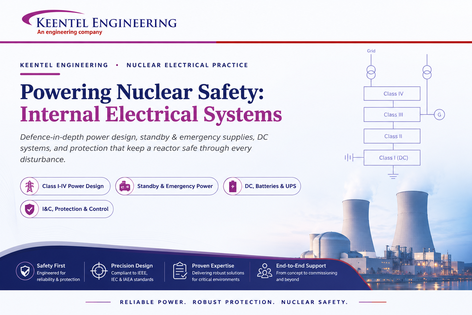
Learn how Class I–IV electrical systems, defence-in-depth, standby and emergency power, DC systems, protection, and load transfer ensure nuclear power plant safety.
By SANDIP R PATEL
•
July 24, 2026
Learn GIS substation safety best practices, SOPs, commissioning, maintenance, interlocking, earthing, and testing to improve grid reliability and uptime.
By SANDIP R PATEL
•
July 23, 2026
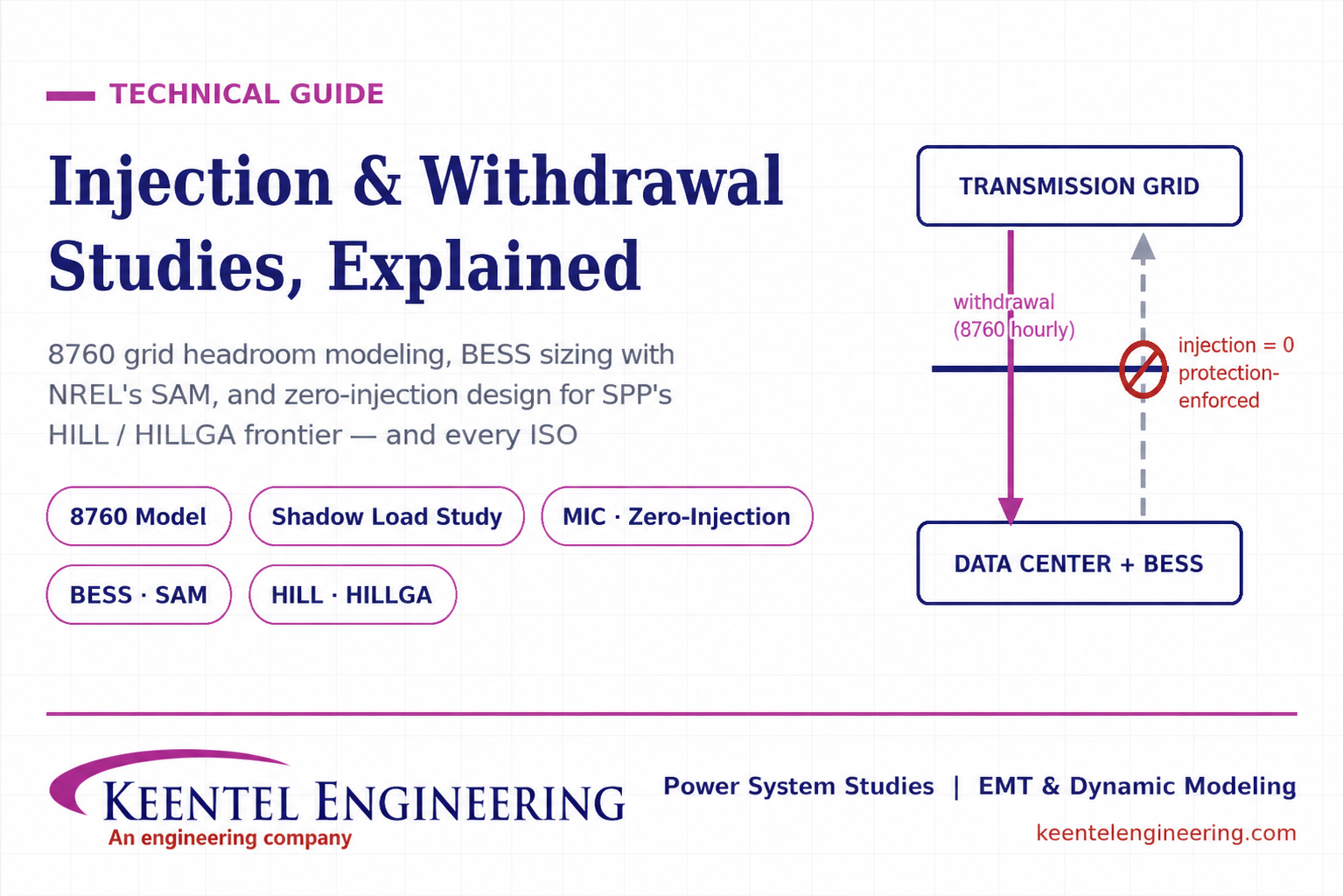
Learn how injection and withdrawal studies, 8760 headroom modeling, zero-injection engineering, and SPP HILLGA improve large load grid interconnections
By SANDIP R PATEL
•
July 21, 2026
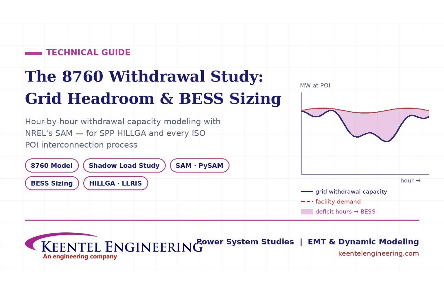
Learn how an 8760 withdrawal study models hourly grid headroom and uses SAM-based BESS sizing for large-load interconnection projects.
By SANDIP R PATEL
•
July 21, 2026
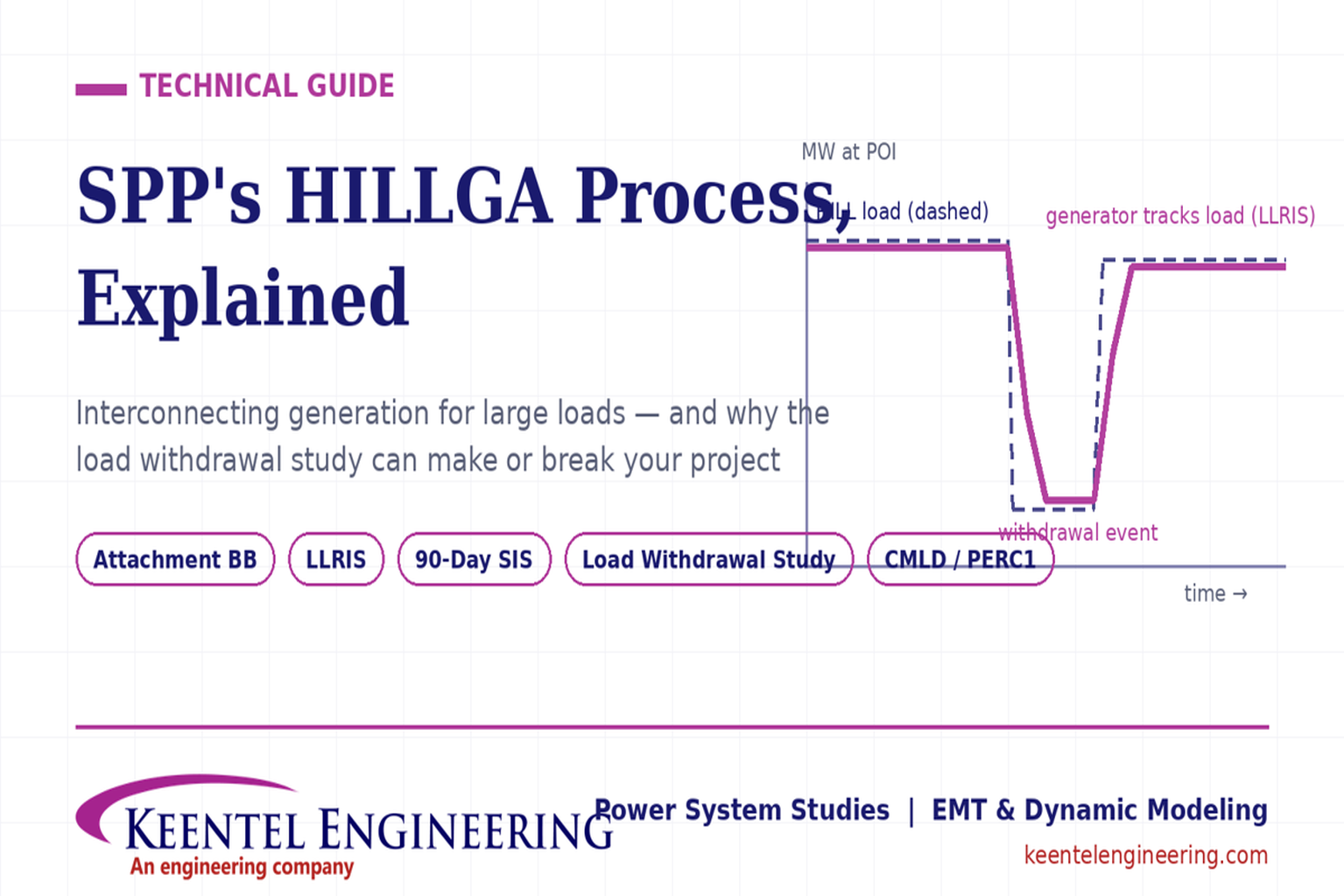
Learn how the SPP HILLGA process supports data center generation interconnection and why an 8760 withdrawal study can determine project success.
By SANDIP R PATEL
•
July 19, 2026
Learn electrical protection and relay coordination for hyperscale data centers with IEEE standards, short-circuit studies, arc-flash analysis, and MV protection.
By SANDIP R PATEL
•
July 18, 2026
Explore Battery Energy Storage System components, including cells, PCS, BMS, EMS, cooling, fire protection, sizing, safety, and grid codes.
By SANDIP R PATEL
•
July 18, 2026
Explore how grid-forming inverters support BESS, synthetic inertia, grid-code compliance, plant sizing, testing, and project revenue.