
A Coordinated Electric System Interconnection Review—the utility’s deep-dive on technical and cost impacts of your project.
Challenge: Frequent false tripping using conventional electromechanical relays
Solution: SEL-487E integration with multi-terminal differential protection and dynamic inrush restraint
Result: 90% reduction in false trips, saving over $250,000 in downtime
ERCOT enforces all of the above through simulation, which means your model is your compliance case. The bar is now high:
- Whole-facility scope. The model must represent everything the IT load, the UPS and power conversion, the cooling plant, the protection and control systems in formats compatible with ERCOT's study platforms (PSS/E, PSCAD, TSAT).
- Real control loops, not approximations. Generic textbook representations are unacceptable. The model must capture the actual inner control behavior of your power electronics.
- Hardware-validated converter models. For electronic loads, the PSCAD model must be benchmarked against actual hardware testing including voltage ride-through and subsynchronous response. A model assembled from standard PSCAD library blocks fails by definition, because a generic block has never been tested against your vendor's hardware. The good news: validation is a hardware-type test, so results for a given converter product are reusable across every facility that uses it.
- Format migration. Facilities that previously submitted the older composite load model (CMLD) format must transition to EPRI's PERC1 format.
- Three checkpoints. Models are reviewed before the stability study begins (no model, no study), before each quarterly stability assessment, and for electronic loads one final time before energization, when you must submit as-built models with a documented comparison against the previously studied data and a sworn attestation that the model matches actual field settings. ERCOT's review takes 10 business days, extendable by 20 put it on your critical path.
- A living obligation. Change your technology, controls, or relay settings in a way that affects ride-through including converting a crypto mining site to an AI data center — and you've triggered a new interconnection study, even if your megawatts don't change.
| Parameter | Detail |
|---|---|
| System | 230 kV / 138 kV transmission corridors, wind and wet-snow icing exposure |
| Data basis | 15 years of minute-resolution forced-outage records + regional weather observations |
| Core methods | Event grouping, MVA performance curves, time-to-95%-restore, area outage rate curves, fragility modeling, rerun-history benefits, exceedance and log-domain risk metrics |
| Headline result | ≈85% of maximum resilience benefit at 60% of original capital; worst-event restoration window cut from 11 days to 5 in rerun-history terms |
| Decision supported | Capital portfolio selection; resilience plan filing; post-investment verification framework |
| System / Topic | Governing Standard(s) | What It Controls |
|---|---|---|
| Overall plant electrical distribution | IEEE 141 (Red Book); IEEE 666 | Distribution architecture, voltage selection, design of generating station auxiliary service systems |
| Power system studies | IEEE 399 (Brown Book); IEEE 551 | Load flow, symmetrical/asymmetrical short circuit, motor starting methodologies down to the lowest LV panelboard |
| Protection & coordination | IEEE 242 (Buff Book); IEEE 3004.5; IEEE C37 series | Generator relaying (21, 59N, 87G), time-current coordination, selective clearing between LV and MV tiers |
| GSU / UAT / SST transformers | IEEE C57.12.00 and C57 family | Transformer ratings, impedance, testing, loading |
| HV switchyard breakers | IEEE C37.06 | AC high-voltage circuit breaker preferred ratings |
| MV switchgear (13.8 kV) | IEEE C37.20.2; IEEE C37.20.7 | Metal-clad construction, compartmentalization, vacuum breakers; arc-resistant design with plenum venting |
| MV cable | UL 1072; ICEA S-93-639 (NEMA WC 74) | Type MV-105 shielded cable, 133% insulation level for HRG systems |
| LV switchgear (480 V) | IEEE C37.13; UL 1558 | Metal-enclosed LV power circuit breaker switchgear to 635 V, draw-out ACBs with electronic trip units |
| Motor control centers | UL 845; NEMA ICS 18 | LV-MCC construction, MCCB/MCP protection for motors under ~200 HP |
| Motors | NEMA MG-1 | Motor performance, starting characteristics, service factors |
| DC & battery systems | IEEE 485; IEEE 946 | Lead-acid battery sizing (125/250 VDC), DC auxiliary system design |
| Grounding | IEEE 80; IEEE 142 (Green Book) | Ground grid step/touch potential limits; system grounding including high-resistance grounding |
| Lightning protection | IEEE 998 | Direct-stroke shielding of switchyard and outdoor generator structures |
| Arc flash & electrical safety | IEEE 1584; NFPA 70E | Incident energy calculation; worker safety boundaries and PPE |
| Fire protection | NFPA 850 | Fire protection and risk management for combustion turbine generating plants |
| Installation code | NEC (NFPA 70); NESC | Wiring methods inside the plant fence; overhead/outdoor clearances at the switchyard |
| Interconnection & compliance | FERC LGIP; NERC MOD-025/026/027, PRC-019/024/029, FAC-008 | Interconnection process, model validation, protection/ride-through coordination, facility ratings |
| IFC / Construction Deliverable | Purpose |
|---|---|
| Stamped IFC packages | Legal basis for construction; P.E. responsible charge |
| Final relay settings & TCCs | Protection as-installed matches the coordination study |
| Calculation archive | Owner records; NERC audit evidence trail |
| Commissioning procedures | Safe, sequenced energization; MOD field testing |
| Construction support | RFIs, field changes, FAT/SAT witness |
| As-builts & model handoff | Operating baseline; future study currency |
| Metric | Outcome |
|---|---|
| Defects found pre-occupancy | Three topology defects and one settings-mismatch family corrected before load migration; the shared-switchboard defect alone would have invalidated the concurrently-maintainable claim on day one |
| IST findings | Fourteen additional discrepancies surfaced under scenario testing (control logic, alarm mapping, one generator sequencing fault) — all closed before handover instead of during operations |
| Black-building test | Passed on second execution; the first attempt exposed the generator sequencing fault under true block load, exactly the failure the compressed plan would never have found |
| Handover quality | Operations team certified on the actual failure scenarios; corrected EOPs and settings documentation delivered as controlled documents |
| Business outcome | Occupancy proceeded three weeks behind the original date — against an independent estimate that the uncorrected sequencing fault carried a high probability of a full facility outage within the first year |
Part 2 — Frequently Asked Questions: Large Load Interconnection
| Contact | Details |
|---|---|
| Headquarters | 400 N Ashley Dr STE 2600, Tampa, FL 33602 |
| Phone | (813) 389-7871 |
| contact@keentelengineering.com | |
| Florida Firm Registration | No. 36853 |
| Additional Offices | Austin, TX • Sacramento, CA • Baltimore, MD |
| Who | Acronym | Plain-English Role |
|---|---|---|
| ERCOT | — | The grid's air traffic controller. It doesn't own power lines or plants; it directs the flow of electricity across most of Texas and referees the admission process for new generators. |
| Interconnecting Entity | IE | You — the developer or owner trying to connect a new plant (or significantly modify an existing one). You file the application and drive the process. |
| Resource Entity | RE | The registered owner/operator of the generator once it becomes an official market participant. Often the same company as the IE, wearing a different hat. |
| Qualified Scheduling Entity | QSE | Your plant's voice on the grid. The QSE handles round-the-clock communications with ERCOT — telemetry, schedules, dispatch instructions. Every generator must have one. |
| Transmission Service Provider | TSP | The utility that owns the wires and substation you'll connect to. The TSP runs your detailed study, builds the connection facilities, and signs your interconnection contract. |
| RIOO-IS | — | ERCOT's online portal where the whole process lives — applications, documents, status tracking, and checklists all flow through it. |
| Who | Acronym | Plain-English Role |
|---|---|---|
| ERCOT | — | The grid's air traffic controller. It doesn't own power lines or plants; it directs the flow of electricity across most of Texas and referees the admission process for new generators. |
| Interconnecting Entity | IE | You — the developer or owner trying to connect a new plant (or significantly modify an existing one). You file the application and drive the process. |
| Resource Entity | RE | The registered owner/operator of the generator once it becomes an official market participant. Often the same company as the IE, wearing a different hat. |
| Qualified Scheduling Entity | QSE | Your plant's voice on the grid. The QSE handles round-the-clock communications with ERCOT — telemetry, schedules, dispatch instructions. Every generator must have one. |
| Transmission Service Provider | TSP | The utility that owns the wires and substation you'll connect to. The TSP runs your detailed study, builds the connection facilities, and signs your interconnection contract. |
| RIOO-IS | — | ERCOT's online portal where the whole process lives — applications, documents, status tracking, and checklists all flow through it. |
| Who | Acronym | Plain-English Role |
|---|---|---|
| ERCOT | — | The grid's air traffic controller. It doesn't own power lines or plants; it directs the flow of electricity across most of Texas and referees the admission process for new generators. |
| Interconnecting Entity | IE | You — the developer or owner trying to connect a new plant (or significantly modify an existing one). You file the application and drive the process. |
| Resource Entity | RE | The registered owner/operator of the generator once it becomes an official market participant. Often the same company as the IE, wearing a different hat. |
| Qualified Scheduling Entity | QSE | Your plant's voice on the grid. The QSE handles round-the-clock communications with ERCOT — telemetry, schedules, dispatch instructions. Every generator must have one. |
| Transmission Service Provider | TSP | The utility that owns the wires and substation you'll connect to. The TSP runs your detailed study, builds the connection facilities, and signs your interconnection contract. |
| RIOO-IS | — | ERCOT's online portal where the whole process lives — applications, documents, status tracking, and checklists all flow through it. |
| Who | Acronym | Plain-English Role |
|---|---|---|
| ERCOT | — | The grid's air traffic controller. It doesn't own power lines or plants; it directs the flow of electricity across most of Texas and referees the admission process for new generators. |
| Interconnecting Entity | IE | You — the developer or owner trying to connect a new plant (or significantly modify an existing one). You file the application and drive the process. |
| Resource Entity | RE | The registered owner/operator of the generator once it becomes an official market participant. Often the same company as the IE, wearing a different hat. |
| Qualified Scheduling Entity | QSE | Your plant's voice on the grid. The QSE handles round-the-clock communications with ERCOT — telemetry, schedules, dispatch instructions. Every generator must have one. |
| Transmission Service Provider | TSP | The utility that owns the wires and substation you'll connect to. The TSP runs your detailed study, builds the connection facilities, and signs your interconnection contract. |
| RIOO-IS | — | ERCOT's online portal where the whole process lives — applications, documents, status tracking, and checklists all flow through it. |
| Who | Acronym | Plain-English Role |
|---|---|---|
| ERCOT | — | The grid's air traffic controller. It doesn't own power lines or plants; it directs the flow of electricity across most of Texas and referees the admission process for new generators. |
| Interconnecting Entity | IE | You — the developer or owner trying to connect a new plant (or significantly modify an existing one). You file the application and drive the process. |
| Resource Entity | RE | The registered owner/operator of the generator once it becomes an official market participant. Often the same company as the IE, wearing a different hat. |
| Qualified Scheduling Entity | QSE | Your plant's voice on the grid. The QSE handles round-the-clock communications with ERCOT — telemetry, schedules, dispatch instructions. Every generator must have one. |
| Transmission Service Provider | TSP | The utility that owns the wires and substation you'll connect to. The TSP runs your detailed study, builds the connection facilities, and signs your interconnection contract. |
| RIOO-IS | — | ERCOT's online portal where the whole process lives — applications, documents, status tracking, and checklists all flow through it. |
| Who | Acronym | Plain-English Role |
|---|---|---|
| ERCOT | — | The grid's air traffic controller. It doesn't own power lines or plants; it directs the flow of electricity across most of Texas and referees the admission process for new generators. |
| Interconnecting Entity | IE | You — the developer or owner trying to connect a new plant (or significantly modify an existing one). You file the application and drive the process. |
| Resource Entity | RE | The registered owner/operator of the generator once it becomes an official market participant. Often the same company as the IE, wearing a different hat. |
| Qualified Scheduling Entity | QSE | Your plant's voice on the grid. The QSE handles round-the-clock communications with ERCOT — telemetry, schedules, dispatch instructions. Every generator must have one. |
| Transmission Service Provider | TSP | The utility that owns the wires and substation you'll connect to. The TSP runs your detailed study, builds the connection facilities, and signs your interconnection contract. |
| RIOO-IS | — | ERCOT's online portal where the whole process lives — applications, documents, status tracking, and checklists all flow through it. |
| Who | Acronym | Plain-English Role |
|---|---|---|
| ERCOT | — | The grid's air traffic controller. It doesn't own power lines or plants; it directs the flow of electricity across most of Texas and referees the admission process for new generators. |
| Interconnecting Entity | IE | You — the developer or owner trying to connect a new plant (or significantly modify an existing one). You file the application and drive the process. |
| Resource Entity | RE | The registered owner/operator of the generator once it becomes an official market participant. Often the same company as the IE, wearing a different hat. |
| Qualified Scheduling Entity | QSE | Your plant's voice on the grid. The QSE handles round-the-clock communications with ERCOT — telemetry, schedules, dispatch instructions. Every generator must have one. |
| Transmission Service Provider | TSP | The utility that owns the wires and substation you'll connect to. The TSP runs your detailed study, builds the connection facilities, and signs your interconnection contract. |
| RIOO-IS | — | ERCOT's online portal where the whole process lives — applications, documents, status tracking, and checklists all flow through it. |
Gas-Insulated Substations for Industrial & Utility Power
Jul 27, 2026 | Blog
A field-tested design review, FAQ, and four project case studies — anchored in a landmark 138 kV GIS cogeneration install
Why Gas-Insulated Substations Still Win the Hard Sites
What a 138 kV cogeneration substation from the golden age of GIS teaches us about compact, low-maintenance high-voltage design in 2026.
The problem every crowded plant eventually hits
Sooner or later, an industrial site runs out of room. A cogeneration unit gets added next to an already-dense process area. A data hall needs 200 MW where there used to be a parking lot. A utility must rebuild a downtown substation on the same fenced footprint it has occupied since the 1960s. In every one of these situations the electrical engineer faces the same wall: a conventional air-insulated substation (AIS) at transmission voltage simply needs a lot of land, a lot of vertical clearance, and a lot of exposed energized steel that people, cranes, and weather can all reach.
The most instructive answer to that problem is not a new one. A widely cited IEEE Petroleum & Chemical Industry Committee paper — R. L. Doughty’s “Design of a 138 kV Gas Insulated Substation for a Large Industrial Cogeneration Facility” (PCIC-89-13) — documented a gas-insulated substation (GIS) built inside a petrochemical plant to tie a 120 MVA gas-turbine cogeneration unit into a 138 kV system. Decades later it remains one of the clearest end-to-end walkthroughs of *why* an engineering team chooses GIS, and *what* that choice actually commits you to. Keentel Engineering revisits it here because almost every design tension it describes is live again today, only now with an added regulatory dimension around the insulating gas itself.
A GIS packs the same 138 kV switching, isolating, grounding, metering, and protection functions of an open-air yard into an SF₆-filled enclosure roughly the footprint of a shipping container. On a constrained site, that density is not a luxury — it is what makes the project buildable at all.
The project in one paragraph
A General Electric Frame 7 combustion gas turbine driving a 120 MVA generator (0.85 power factor, 13.8 kV) was installed at a Gulf-region petrochemical plant. An 80/119 MVA step-up transformer lifted the generator output to 138 kV. There was no room for an outdoor yard and no appetite for stringing overhead lines across a plant full of tall process equipment and mobile cranes. So the team specified a compact GIS in a dedicated building, fed the 138 kV connection out through underground low-pressure oil-filled (LPOF) cable running about 600 feet in a concrete duct bank to the existing plant substation, and sized the whole arrangement as a ring bus so a second cogeneration unit could be added later without a rebuild. Two years after commissioning, the unit was running at better than 98% availability.
Eight reasons the team chose GIS and why they still hold
The paper lays out a decision rationale that reads like a checklist any modern owner can reuse. The eight drivers were:
- Compact footprint that made the installation physically possible and left room for a future second unit.
- Elimination of overhead 138 kV line hazards to plant vehicular traffic — critically, mobile cranes working near a process unit.
- No exposed energized conductors or bushings for personnel to contact.
- Reduced impact of airborne pollutants on the electrical system — a real concern in a petrochemical atmosphere that coats and corrodes open insulators.
- ~30% lower electrical maintenance cost for the 138 kV equipment, with minimal cable maintenance expected once the LPOF system was commissioned.
- Reliability equal to or better than a conventional substation.
- A cleaner visual profile for the facility.
- Life-cycle cost equal to or below a conventional substation, despite the higher initial price.
That last point is the one decision-makers most often get wrong. GIS almost always costs more to buy. The case for it is made on land, safety, availability, and lifetime maintenance — not on the sticker. When those four are constrained, GIS frequently wins the total-cost argument even though it loses the first-cost argument.
Conventional AIS vs. GIS at a glance
| Dimension | Air-Insulated (AIS) | Gas-Insulated (GIS) |
|---|---|---|
| Footprint | Large open yard; wide phase & ground clearances | ~10–20% of the AIS area; enclosed |
| Live parts | Exposed conductors, bushings, buswork | Fully enclosed in grounded metal |
| Environmental exposure | Vulnerable to salt, dust, chemicals, ice | Sealed from the outside atmosphere |
| First cost | Lower | Higher |
| Maintenance | Higher; weather-driven | Lower (paper cites ~30% reduction) |
| Insulating medium | Air + porcelain/composite | SF₆ (now facing phase-down; alternatives emerging) |
| Best fit | Land-rich, lower-cost sites | Space-, safety-, or environment-constrained sites |
The design decisions worth copying
Underground cable instead of overhead line
The transition from the GIS to the plant substation was made with LPOF cable rather than an overhead line. The team accepted a higher initial cost for the cable in exchange for removing the overhead-line hazard entirely, eliminating personnel exposure, and cutting the facility’s exposure to airborne contamination. The 138 kV connection ran as SF₆ bus out of the building, transitioned to 1250 kcmil LPOF cable outdoors above a cable pit, then entered a concrete duct bank. The cable pit was deliberately split into two compartments so a fault or oil fire on one supply cable could not easily damage the other — a small civil detail with a large reliability payoff.
Ring-bus configuration, built half now and half later
The GIS was arranged as a ring bus sized for two incoming 138 kV supplies and two load feeders, but only the portion needed for the first unit was installed, with provision to complete the ring when a second cogeneration unit arrives. A ring bus gives each element two paths to source and lets any single breaker be maintained without dropping load — high reliability without the cost of a full breaker-and-a-half scheme. Designing the ultimate configuration up front, then staging the build, is exactly the kind of foresight that keeps a later expansion from becoming a demolition job.
Synchronizing through the GIS, with reclosing deliberately blocked
In normal operation both 138 kV breakers were closed, and either could be used to synchronize the turbine to the system. Automatic reclosing was intentionally disabled for two reasons: to prevent out-of-synchronism reclosing onto the generator, and to reduce the probability of an internal fault escalating to an enclosure burn-through. This is a good reminder that a GIS changes the fault calculus — an arc that would flash harmlessly to air in an open yard is confined inside an aluminum enclosure, so protection and operating philosophy must respect that confinement.
Protection: layered, overlapping, and fast
Underground cable instead of overhead line
The transition from the GIS to the plant substation was made with LPOF cable rather than an overhead line. The team accepted a higher initial cost for the cable in exchange for removing the overhead-line hazard entirely, eliminating personnel exposure, and cutting the facility’s exposure to airborne contamination. The 138 kV connection ran as SF₆ bus out of the building, transitioned to 1250 kcmil LPOF cable outdoors above a cable pit, then entered a concrete duct bank. The cable pit was deliberately split into two compartments so a fault or oil fire on one supply cable could not easily damage the other — a small civil detail with a large reliability payoff.
Ring-bus configuration, built half now and half later
The GIS was arranged as a ring bus sized for two incoming 138 kV supplies and two load feeders, but only the portion needed for the first unit was installed, with provision to complete the ring when a second cogeneration unit arrives. A ring bus gives each element two paths to source and lets any single breaker be maintained without dropping load — high reliability without the cost of a full breaker-and-a-half scheme. Designing the ultimate configuration up front, then staging the build, is exactly the kind of foresight that keeps a later expansion from becoming a demolition job.
Synchronizing through the GIS, with reclosing deliberately blocked
In normal operation both 138 kV breakers were closed, and either could be used to synchronize the turbine to the system. Automatic reclosing was intentionally disabled for two reasons: to prevent out-of-synchronism reclosing onto the generator, and to reduce the probability of an internal fault escalating to an enclosure burn-through. This is a good reminder that a GIS changes the fault calculus — an arc that would flash harmlessly to air in an open yard is confined inside an aluminum enclosure, so protection and operating philosophy must respect that confinement.
Protection: layered, overlapping, and fast
The protection scheme is a clinic in defense-in-depth for a generation intertie:
- High-impedance instantaneous differential relays protected the 138 kV GIS bus between the step-up transformer and the breakers.
- Harmonic-restrained differential protected the step-up transformer, guarding against false trips on magnetizing inrush.
- An overall differential zone wrapped the whole machine — generator (from the neutral side), 13.8 kV isolated-phase bus, step-up transformer, and 138 kV SF₆ bus up to the breakers — as a backup blanket over the individual zones.
- The line side, underground cable, and connected 138 kV line used a directional-comparison unblocking scheme with frequency-shift carrier, backed by a permissive overreaching transfer-trip using audio-tone equipment.
- Each generator breaker had breaker-failure protection that, on failure, isolated the turbine, tripped the remaining generator breaker, and reached back to the 138 kV backup breakers.
The lesson for owners: in a GIS you cannot walk the yard and visually confirm a problem, and you cannot tolerate a lingering internal arc. That pushes the design toward fast, redundant, overlapping protection with clear backup for every primary function.
Insulation coordination: the study that changed the purchase order
The most technically rich part of the paper is the surge-protection study, and it carries a warning every specifier should hear. The GIS was specified to IEC standards at 145 kV maximum continuous voltage, 650 kV BIL, and 275 kV power-frequency withstand. The step-up transformer windings, though, were only rated 550 kV BIL. To verify that the metal-oxide arresters actually protected both, the team commissioned an EMTP (Electromagnetic Transients Program) study modeling lightning strokes both far from and near the cable-to-overhead-line transition.
The results were sobering. With arresters only at the incoming cable, a nearby stroke drove the calculated safety factor below the IEC minimum of 1.20 at the transformer, and the 550 kV transformer BIL was exceeded in the worst case. The fix was to add SF₆-enclosed metal-oxide arresters on the SF₆ bus, right at the transformer primary bushings (98 kV rms maximum continuous operating voltage). Re-running the study with those arresters raised the GIS safety factor to 1.62 and the transformer to 1.74 — comfortably above the 1.50 target. The purchase order was amended accordingly.
Takeaway: arrester placement is not a formality you can bolt on at the incoming line and forget. In a GIS, steep-front surges travel fast through low-impedance bus, and the equipment they threaten most may be the transformer behind the switchgear. Model it before you buy it.
The building around the switchgear is part of the design
A GIS is not just apparatus — it is apparatus plus a building plus a gas-handling regime, and the paper treats all three as one system. The SF₆ building was a steel-frame, precast-concrete structure roughly 50 ft long by 26 ft wide by 26 ft high, finished as a near clean-room: white walls, dust-suppressing floor coating, and full HVAC operating *before* the GIS ever arrived so the equipment was received into a clean, protected environment.
Because SF₆ is about five times heavier than air, colorless, and odorless, it pools in low spots and can displace breathable air. The building answered that with a ventilation system providing constant fresh-air makeup, floor-level SF₆ detectors that trigger exhaust fans and dampers to sweep the floor, an alarm in the control room, and a flashing warning light at the entrance.
Below-grade cable pits required a confined-space (vessel entry) procedure, and any maintenance on arced compartments demanded special handling because SF₆ decomposition products are toxic. None of this is optional folklore — it is the safety envelope that makes an enclosed high-voltage gas system livable for the people who operate it.
The civil interface nobody expects: differential settlement
One of the paper’s most quietly valuable sections concerns foundations. A rigid SF₆ bus connecting a heavy step-up transformer to the GIS cannot tolerate much relative movement.
The team allowed only about 0.25 inches of differential settlement between the transformer and GIS foundations and roughly 0.50 inches of vertical bus movement, using a flexible bellows at the transformer connection to absorb vibration and thermal growth, and a saddle support that let the bus flex as a cantilever. Because ordinary shallow foundations could not guarantee those tolerances, civil engineers specified under-reamed (belled) footings for the building, the GIS, and the transformer, and took benchmark elevation readings after installation to track settlement over time. The point generalizes: a GIS forces the electrical and civil disciplines to design to each other’s tolerances, far more tightly than an AIS ever does.
Key ratings from the installation
For reference, the headline equipment ratings that defined the design:
| Parameter | Value |
|---|---|
| System / max continuous voltage | 138 kV / 145 kV, solidly grounded |
| Basic Insulation Level (BIL) | 650 kV (GIS); 550 kV (transformer windings) |
| Power-frequency withstand | 275 kV |
| Short-circuit interrupting | 40 kA rms symmetrical |
| Close-and-latch capability | 64 kA |
| Rated interrupting time | 45 ms (2.7 cycles) |
| Breaker continuous rating | 1200 A (main bus 2500 A; transformer SF₆ bus 600 A) |
| SF₆ pressure | 6 bar in breakers; 3.5 bar in other compartments |
| CT relaying accuracy class | C400 |
| Arrester MCOV (added at transformer) | 98 kV rms |
| Generator / step-up transformer | 120 MVA, 13.8 kV / 80–119 MVA, 144–13.8 kV |
| Result after 2 years | > 98% operating availability |
Reading the 1989 design through a 2026 lens
Everything above still applies. What has changed is the gas. SF₆ is an extraordinary insulator and arc-quencher, but it is also the most potent greenhouse gas known, with a global-warming potential on the order of 23,000–25,000 times CO₂ and an atmospheric lifetime measured in millennia. Regulators have moved. The EU’s F-gas Regulation (EU) 2024/573 phases SF₆ out of new switchgear on a voltage-tiered schedule — new equipment up to 24 kV from 2026, the 52–145 kV class (which includes 138 kV) restricted from 2028, and higher voltages from 2032, with narrow exemptions where no suitable alternative exists. In the U.S., SF₆ use and emissions face growing EPA and state-level reporting and reduction pressure.
The industry’s response is a new generation of insulating media: fluoronitrile (C4-FN) mixtures marketed as “clean-air” or “g³” solutions, fluoroketone (C5-FK) blends, and technical/vacuum approaches at lower voltages — all aiming to cut GWP by 99%+ while preserving GIS’s compactness. For an
owner specifying a 138 kV GIS today, the Doughty design principles are unchanged; the specification simply gains a new line item: which insulating gas, at what handling and end-of-life cost, under which regulatory horizon. That is precisely the kind of trade-off Keentel helps clients frame before the purchase order is cut.
What Keentel takes from this paper
- Specify for the whole life, not the first invoice. GIS wins on land, safety, availability, and maintenance — build the business case there.
- Design the ultimate one-line, build the first stage. A ring bus sized for expansion turns a future rebuild into a bolt-on.
- Model your surges before you buy. An EMTP/insulation-coordination study can move an arrester and save a transformer.
- Treat the building, gas handling, and foundations as part of the electrical design — not as someone else’s scope.
- Put the gas question on the table early. With SF₆ phase-downs underway, insulating-medium choice now shapes lifecycle cost and compliance.
Have a constrained site, a generation intertie, or an aging yard you cannot expand? That is exactly the conversation this paper was written for — and the one our team has most weeks. Talk to Keentel Engineering about whether GIS is the right answer for your footprint.
Four GIS Applications, Four Different Constraints
How gas-insulated design solves the space, safety, and reliability problem across very different sectors.
Note: The following are anonymized, representative engagements. Locations and identifying details have been generalized; technical parameters are illustrative of typical projects in each sector and are consistent with the design principles discussed above.
Case Study 1 — Downtown Utility Rebuild on a Frozen Footprint
| Sector | Electric utility (transmission & distribution) |
|---|---|
| Scope | Dense downtown core, major North American metro (anonymized) |
| Location | Replace an aging 138/13.8 kV air-insulated substation in place |
| Solution | 230/138 kV-class indoor GIS + underground cable getaways |
The challenge
A utility needed to rebuild a 1960s-era air-insulated substation that fed a growing downtown load pocket. The site was hemmed in on all four sides by streets and commercial buildings — acquiring adjacent land was impossible, and the existing yard could not be enlarged. Load growth demanded more capacity and a second transmission source yet the substation had to keep serving the neighborhood throughout construction.
The Keentel approach
The team specified a compact indoor GIS that fit the entire high-voltage lineup into a two-story equipment building on the original parcel, with underground cable getaways replacing the overhead line terminations that had dominated the old yard. A staged cutover kept the legacy AIS energized while the GIS was built alongside it, then transferred feeders bay by bay. Because the GIS is sealed and indoors, the design also removed the utility’s chronic problems with urban salt, grime, and pigeon-related flashovers on open insulators.
The outcome
Capacity and a redundant source were added on the same footprint, with a cleaner streetscape and no overhead transmission over city sidewalks. Projected maintenance dropped sharply because the switchgear no longer weathered the urban atmosphere, and the utility gained a template it now reuses for other landlocked downtown sites. An SF₆-free (fluoronitrile) option was evaluated against the phase-down timeline and held as the preferred medium for the next phase.
Case Study 2 — Hyperscale Data Center Campus Intertie
| Sector | Digital infrastructure / hyperscale data center |
|---|---|
| Location | Suburban technology corridor (anonymized) |
| Scope | 230 kV utility intertie for a 300 MW multi-building campus |
| Solution | Compact GIS switching station + redundant transformer bays |
The challenge
A hyperscale operator needed to bring hundreds of megawatts onto a campus where every acre was earmarked for revenue-generating data halls, not electrical yard. Uptime was non-negotiable — the intertie had to support concurrent maintenance with zero load interruption — and the utility’s timeline for energization was aggressive.
The Keentel approach
The design used a GIS switching station in a footprint a fraction of the AIS equivalent, freeing land for additional halls. The bus was arranged for N-1 redundancy with concurrent maintainability so any breaker or transformer bay could be isolated without dropping the campus, mirroring the ring-bus philosophy of building the ultimate configuration and staging capacity as new buildings come online. Fast, redundant differential and breaker-failure protection matched the facility’s tolerance for downtime — effectively zero.
The outcome
The campus secured its full power block on minimal land, with a switching arrangement that supports live expansion as each new data hall is commissioned. The compact GIS also compressed the construction schedule, helping the operator hit its energization date. The reduced maintenance profile and enclosed design fit a lights-out site with a small on-site electrical staff.
Case Study 3 — Offshore-Fed Renewable Collector Substation
| Sector | Renewable energy (offshore wind collector / grid tie-in) |
|---|---|
| Location | Coastal landfall, North Atlantic seaboard (anonymized) |
| Scope | Onshore 220 kV collector substation for an offshore wind farm |
| Solution | Fully enclosed GIS to survive a salt-fog, corrosive environment |
The challenge
An offshore wind development landed its export cables at a coastal site subject to relentless salt fog, wind-driven moisture, and corrosion — an environment that punishes exposed air-insulated equipment. The collector substation also had a compact coastal parcel with strict visual and environmental constraints from local stakeholders.
The Keentel approach
A fully enclosed GIS was the natural fit: sealing the live parts from the marine atmosphere directly addressed the corrosion and contamination problem that would otherwise drive constant maintenance and flashover risk. Underground cable terminations brought the export circuits into the GIS, keeping the site low-profile to satisfy visual concerns. The enclosed arrangement also simplified environmental permitting relative to a sprawling open yard on a sensitive shoreline.
The outcome
The substation delivered a weatherproof, low-visual-impact tie-in that keeps the wind farm exporting reliably through coastal storms, with dramatically reduced exposure-driven maintenance. As with the other engagements, a reduced-GWP insulating medium was evaluated up front so the asset aligns with tightening emissions rules over its multi-decade life.
Case Study 4 — Remote Mining & Minerals Processing Complex
| Sector | Heavy industry (mining & minerals processing) |
|---|---|
| Location | High-altitude arid interior, remote region (anonymized) |
| Scope | 138 kV incoming substation for a mine and processing plant |
| Solution | GIS engineered for altitude, dust, seismic, and remoteness |
The challenge
A minerals processing complex sat at high altitude in a remote, seismically active, dust-laden region. Thin air reduces the dielectric strength of air-insulated equipment (forcing larger clearances), airborne dust coats insulators, seismic activity threatens tall rigid structures, and the site’s remoteness made frequent maintenance visits costly and slow. The plant’s process loads also could not tolerate extended outages.
The Keentel approach
A GIS resolved several constraints at once. Because the insulation is inside a pressurized enclosure rather than relying on ambient air, altitude derating and dust contamination largely fall away, and the compact, low-mass arrangement is far easier to seismically qualify than a tall open yard. Echoing the cogeneration reference case, the design paid close attention to the civil interface — foundations and bus flexibility tuned to seismic and settlement conditions — and to layered protection that keeps process loads stable. The low-maintenance, sealed design directly answered the remoteness problem.
The outcome
The complex received a robust, low-maintenance high-voltage supply that shrugs off altitude, dust, and seismic events, with long maintenance intervals suited to a site where every service trip is expensive. The result is exactly the value proposition the 1989 cogeneration paper first articulated — compact size, improved safety, and reduced maintenance — carried into a modern, hostile-environment application.
About this briefing
This document is a Keentel Engineering technical-content piece reviewing IEEE PCIC-89-13, “Design of a 138 kV Gas Insulated Substation for a Large Industrial Cogeneration Facility” (R. L. Doughty, E. I. du Pont de Nemours and Company). Technical figures attributed to “the reference project” are drawn from that paper. Regulatory and alternative-gas context reflects the EU F-gas Regulation (EU) 2024/573 and industry sources current as of July 2026. Case studies are anonymized, representative composites for illustration.
Gas-Insulated Substations: In-Depth FAQ
Straight answers to the questions engineers, project managers, and owners ask most often when weighing GIS — grounded in the 138 kV cogeneration case and current practice.
Q. What exactly is a gas-insulated substation (GIS)?
A GIS performs every function of a conventional open-air substation — busing, switching, isolating, grounding, metering, and protection — but with the live conductors enclosed in grounded metal housings filled with an insulating gas, historically sulfur hexafluoride (SF₆). Because the gas insulates far better than air, the phase-to-phase and phase-to-ground clearances shrink dramatically, which is why a 138 kV GIS can occupy roughly one-tenth to one-fifth of the land an equivalent air-insulated yard needs.
Q. When does GIS make more sense than a conventional air-insulated substation?
Whenever land, safety, environment, or availability is constrained. Classic triggers include tight industrial plots (the cogeneration case had no room for an outdoor yard), dense urban utility sites, offshore and coastal installations, high-pollution or corrosive atmospheres, high-seismic zones, and sites where exposed high-voltage conductors would endanger cranes, traffic, or personnel. If land is cheap and the environment is benign, AIS is usually the lower-cost choice.
Q. Is GIS more expensive?
In first cost, almost always yes — the apparatus, the building, and the gas-handling regime all add up. The case for GIS is made on total cost of ownership: less land, lower maintenance (the reference project projected about a 30% reduction in 138 kV maintenance cost), higher availability, and reduced safety and environmental risk. On a genuinely constrained site, the land and downtime you avoid frequently outweigh the higher purchase price over the asset’s life.
Q. Why choose underground cable over an overhead line to connect the GIS?
In the reference project the team paid a premium for low-pressure oil-filled (LPOF) 138 kV cable specifically to eliminate overhead-line hazards — no exposed conductors over plant traffic and cranes, no personnel exposure to energized parts, and far less vulnerability to airborne contamination. They also split the cable pit into two compartments so a fault or oil fire on one supply cable could not take out the other. Modern equivalents use XLPE or fluid-filled cable, but the reliability-and-safety logic is identical.
Q. What is a ring-bus arrangement and why was it used?
A ring bus connects breakers in a closed loop so every circuit is fed from two directions and any single breaker can be taken out of service without interrupting load. It delivers high reliability at lower cost than a breaker-and-a-half scheme. In the case study the ultimate ring was designed for two supplies and two feeders, but only the first stage was built — with provisions to complete the ring when a second generating unit is added. Design the final one-line, build what you need now.
Q. Why was automatic reclosing disabled?
Two reasons. First, to prevent reclosing the generator out of synchronism with the system, which can severely damage the machine and shaft. Second, to reduce the chance that an internal fault escalates into an enclosure burn-through. In a GIS a fault arc is confined inside a metal housing rather than flashing to open air, so operating philosophy must avoid re-energizing into a possible fault.
Q. What is SF₆ and why has it been the gas of choice?
Sulfur hexafluoride is a colorless, odorless, non-flammable, chemically stable gas with excellent dielectric strength (it insulates roughly three times better than air at the same pressure) and outstanding arc-quenching ability. Those properties let breakers interrupt large fault currents in a small volume. The reference GIS held about 6 bar of SF₆ in the breakers and 3.5 bar in other compartments.
Q. If SF₆ is inert, why all the safety precautions?
Pure SF₆ is physiologically inert, but it is about five times denser than air, so it sinks and pools in low areas — cable pits, trenches, basements — where it can displace oxygen and asphyxiate people without warning. And once it has been exposed to an electric arc, its decomposition byproducts are toxic and corrosive. That is why GIS buildings use floor-level gas detection, forced ventilation that sweeps the floor, control-room alarms, entrance warning lights, and confined-space entry procedures for below-grade work.
Q. Is SF₆ being phased out, and what does that mean for a project today?Q. Is SF₆ being phased out, and what does that mean for a project today?
Yes, progressively. SF₆ has a global-warming potential roughly 23,000–25,000 times that of CO₂ and persists in the atmosphere for millennia. The EU’s F-gas Regulation (EU) 2024/573 restricts new SF₆ switchgear on a voltage-tiered timetable — up to 24 kV from 2026, the 52–145 kV class from 2028, and higher voltages from 2032, with limited exemptions. In the U.S., EPA and several states are tightening reporting and emission-reduction requirements. For a new project you should evaluate SF₆-free or reduced-GWP alternatives and factor the regulatory horizon into lifecycle cost.
Q. What are the alternatives to SF₆?
The leading options are fluoronitrile (C4-FN) mixtures — often blended with CO₂ and oxygen and marketed as “g³” or clean-air solutions — and fluoroketone (C5-FK) blends, both cutting GWP by well over 99% while preserving most of GIS’s compactness. At lower voltages, technical/synthetic air combined with vacuum interruption is increasingly common. Each alternative has trade-offs in dielectric performance, low-temperature behavior, handling, and cost, so the choice is application-specific.
Q. How is a GIS protected electrically?
With fast, redundant, overlapping schemes because you cannot visually inspect an enclosed fault and cannot let an internal arc persist. The reference design used high-impedance instantaneous differential relays on the SF₆ bus, harmonic-restrained differential on the transformer, an overall differential zone spanning the generator through the SF₆ bus, directional-comparison and transfer-trip schemes on the line, and dedicated breaker-failure protection on every generator breaker.
Q. What is insulation coordination and why did it change the design?
Insulation coordination ensures that surge arresters clamp transient overvoltages (lightning, switching) below the withstand level (BIL) of every piece of equipment, with a safety margin — IEC sets a minimum factor around 1.20, and good practice targets about 1.50. In the case study an EMTP transient study showed that arresters at the incoming cable alone left the 550 kV-BIL transformer under-protected against nearby lightning. Adding SF₆-enclosed arresters at the transformer bushings raised the margins to 1.62 (GIS) and 1.74 (transformer). The lesson: model the surges and place arresters accordingly before finalizing the purchase.
Q. What building and civil work does a GIS require?
More coordination than people expect. The reference GIS sat in a climate-controlled, near-clean-room building erected before the equipment arrived. Foundations were the surprise: the rigid SF₆ bus tolerated only about 0.25 inches of differential settlement between the transformer and GIS, so under-reamed (belled) footings were specified and benchmark elevations were monitored over time, with a flexible bellows absorbing vibration and thermal movement. A GIS makes the electrical and civil disciplines design to each other’s tolerances.
Q. How much maintenance does a GIS need?
Substantially less than AIS because the live parts are sealed away from weather, dust, and contamination. The reference project projected roughly a 30% reduction in 138 kV maintenance cost, and the breakers were specified to withstand at least 25 full-fault operations and 2000 full-load operations without maintenance. The main ongoing tasks are gas-density monitoring, periodic diagnostics, and — increasingly — disciplined gas handling and leak management to meet emission rules.
Q. What kind of availability and service life can be expected?
GIS is a long-life, high-availability technology. The reference cogeneration unit reported better than 98% operating availability two years in, and modern GIS assets are routinely designed for 40+ year service lives. Reliability depends on quality manufacturing, clean installation, sound gas management, and good protection — all of which the reference project treated as first-class design concerns.
Q. Can a GIS be expanded later?
Yes, if you plan for it. Designing the ultimate bus configuration up front and installing only the first stage — as the case study did with its ring bus — lets you add bays or a second source later as a bolt-on rather than a rebuild. Retrofitting expansion that was never designed in is far more disruptive, so expansion strategy belongs in the earliest design conversations.
Q. What kind of availability and service life can be expected?
GIS is a long-life, high-availability technology. The reference cogeneration unit reported better than 98% operating availability two years in, and modern GIS assets are routinely designed for 40+ year service lives. Reliability depends on quality manufacturing, clean installation, sound gas management, and good protection — all of which the reference project treated as first-class design concerns.

About the Author:
Sandip "Sonny" R. Patel, P.E.
IEEE Senior Member · Founder & CEO, Keentel Engineering
In 1995, Sonny Patel earned his Electrical Engineering degree from the University of Illinois. But degrees don't build legacies — action does.
For three decades, he has worked the power industry from every side of the table: 16 years as a utility engineer at Exelon/Commonwealth Edison; generation leadership across hydroelectric, industrial steam turbine, and a 9 GW renewable fleet; NERC Regional Entity Senior Compliance Engineer and Audit Team Lead, auditing some of the nation's largest utilities; and testing and commissioning lead on equipment up to 765 kV — the very top of the North American grid.Utility. Generator. Regulator. Consultant. Few engineers have seen all four seats. Fewer still have sat in them.
His experience spans nuclear, hydro, conventional generation, renewables, oil and gas, mining — and today's data centers, where he is authoring a three-book series on data center design. He is a Licensed Professional Engineer in six states and a Licensed Electrical Contractor in Florida (Unlimited EC) — he doesn't just design the work; he's qualified to stand behind its execution.Today, as Founder and CEO of Keentel Engineering, Sonny leads a nationwide team of engineers delivering substation design, power system studies, NERC compliance, and commissioning — done right, coast to coast.Three decades. Every side of the table. One standard: accountable engineering.
Services

Let's Discuss Your Project
Let's book a call to discuss your electrical engineering project that we can help you with.
About the Author:
Sandip "Sonny" R. Patel, P.E.
IEEE Senior Member · Founder & CEO, Keentel Engineering
In 1995, Sonny Patel earned his Electrical Engineering degree from the University of Illinois. But degrees don't build legacies — action does.
For three decades, he has worked the power industry from every side of the table: 16 years as a utility engineer at Exelon/Commonwealth Edison; generation leadership across hydroelectric, industrial steam turbine, and a 9 GW renewable fleet; NERC Regional Entity Senior Compliance Engineer and Audit Team Lead, auditing some of the nation's largest utilities; and testing and commissioning lead on equipment up to 765 kV — the very top of the North American grid.
Utility. Generator. Regulator. Consultant. Few engineers have seen all four seats. Fewer still have sat in them.
His experience spans nuclear, hydro, conventional generation, renewables, oil and gas, mining — and today's data centers, where he is authoring a three-book series on data center design. He is a Licensed Professional Engineer in six states and a Licensed Electrical Contractor in Florida (Unlimited EC) — he doesn't just design the work; he's qualified to stand behind its execution.
Today, as Founder and CEO of Keentel Engineering, Sonny leads a nationwide team of engineers delivering substation design, power system studies, NERC compliance, and commissioning — done right, coast to coast.Three decades. Every side of the table. One standard: accountable engineering.
Leave a Comment
Thank you for contacting us.
We will get back to you as soon as possible.
We will get back to you as soon as possible.
Oops, there was an error sending your message.
Please try again later.
Please try again later.
Related Posts
By SANDIP R PATEL
•
October 23, 2026
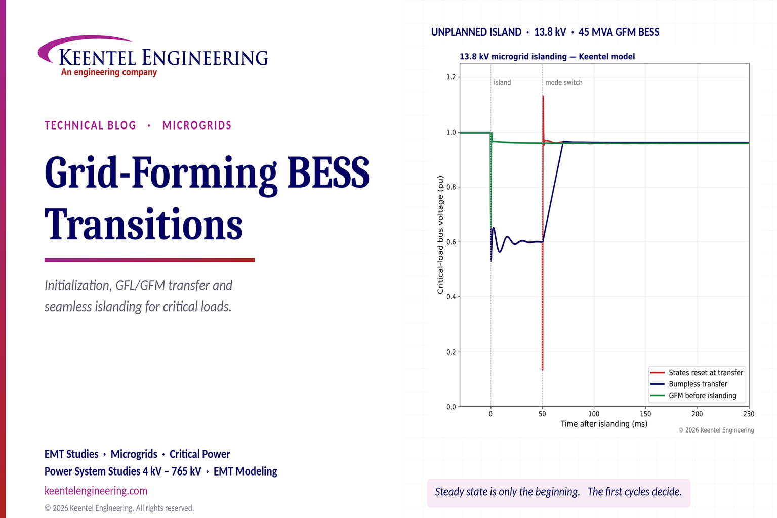
Explore grid-forming BESS initialization, GFL-to-GFM transitions, seamless islanding, EMT simulations, current limiting and microgrid protection.
By SANDIP R PATEL
•
October 23, 2026
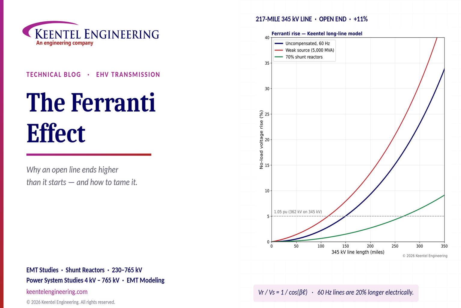
Explore the Ferranti effect in EHV transmission lines: voltage rise, 345 kV examples, switching overvoltages, shunt reactor sizing and mitigation.
By SANDIP R PATEL
•
October 23, 2026
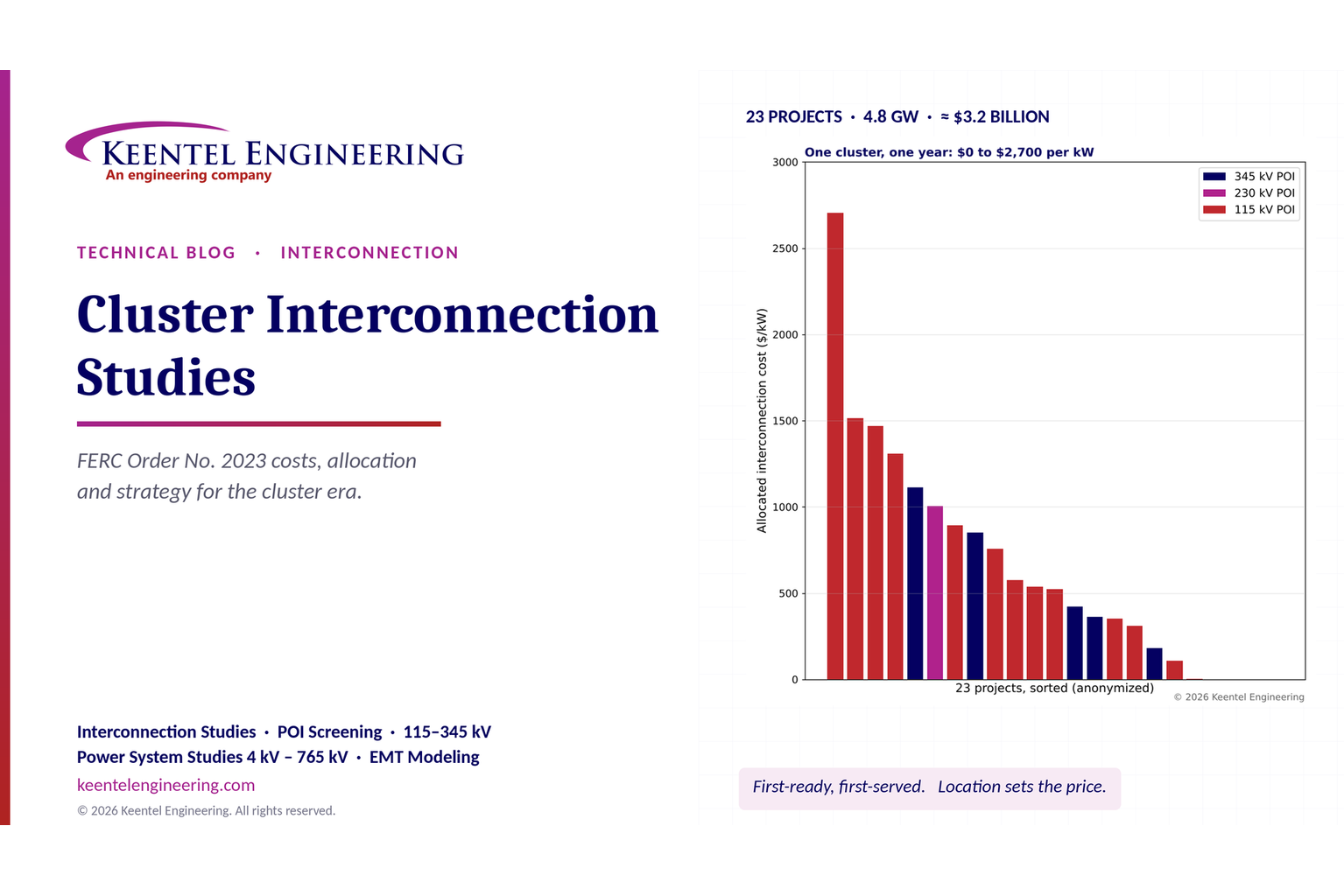
Explore cluster interconnection studies under FERC Order 2023, including network upgrades, cost allocation, withdrawal penalties and developer strategy.
By SANDIP R PATEL
•
October 21, 2026
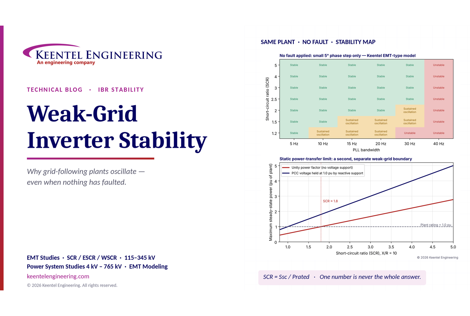
Learn why grid-following inverters become unstable without grid faults. Explore SCR, PLL interactions, EMT studies, grid strength, and mitigation.
By SANDIP R PATEL
•
October 21, 2026
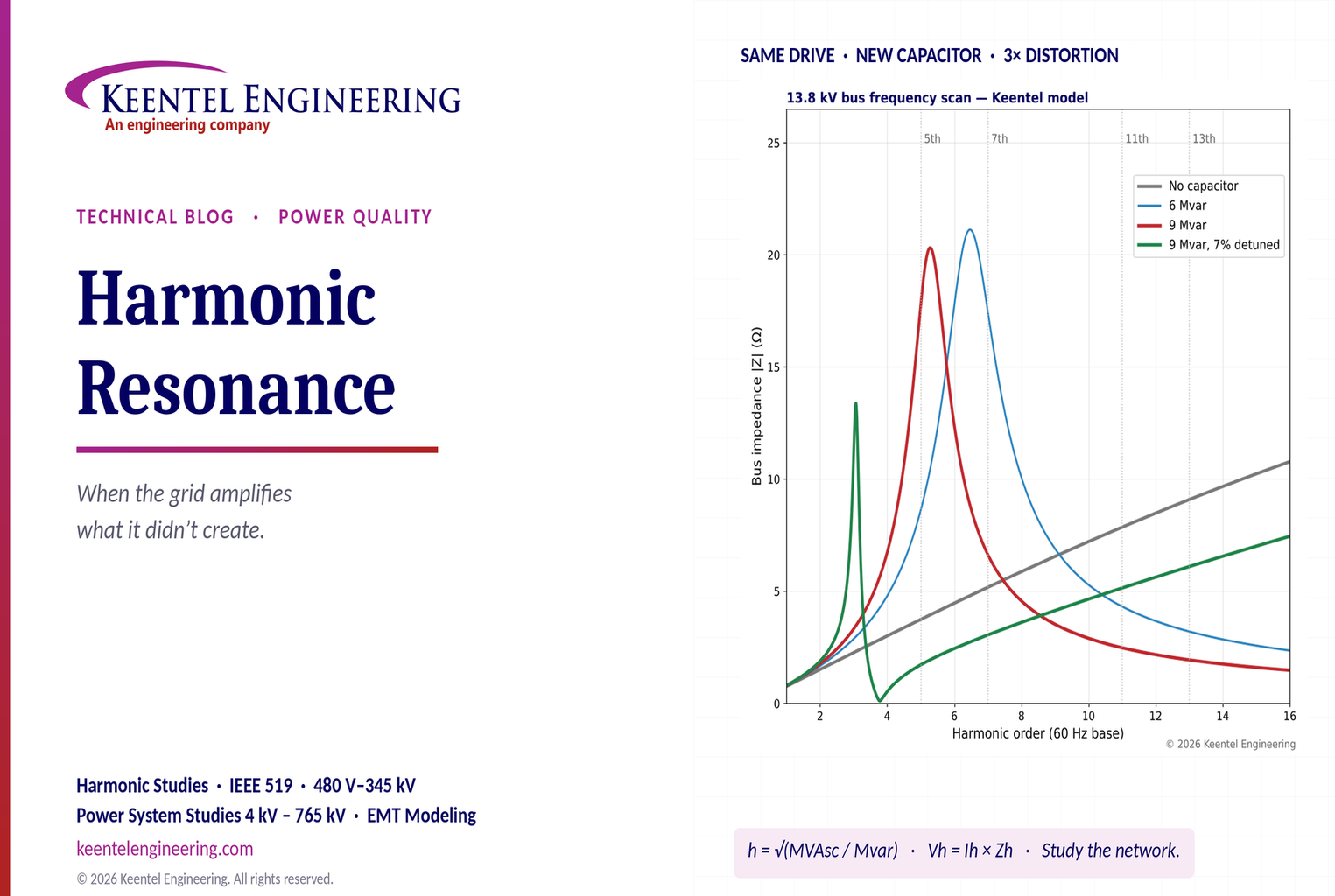
Learn how harmonic resonance amplifies distortion in power systems. Explore capacitor banks, detuned reactors, frequency scans, and IEEE 519 solutions.
By SANDIP R PATEL
•
October 20, 2026
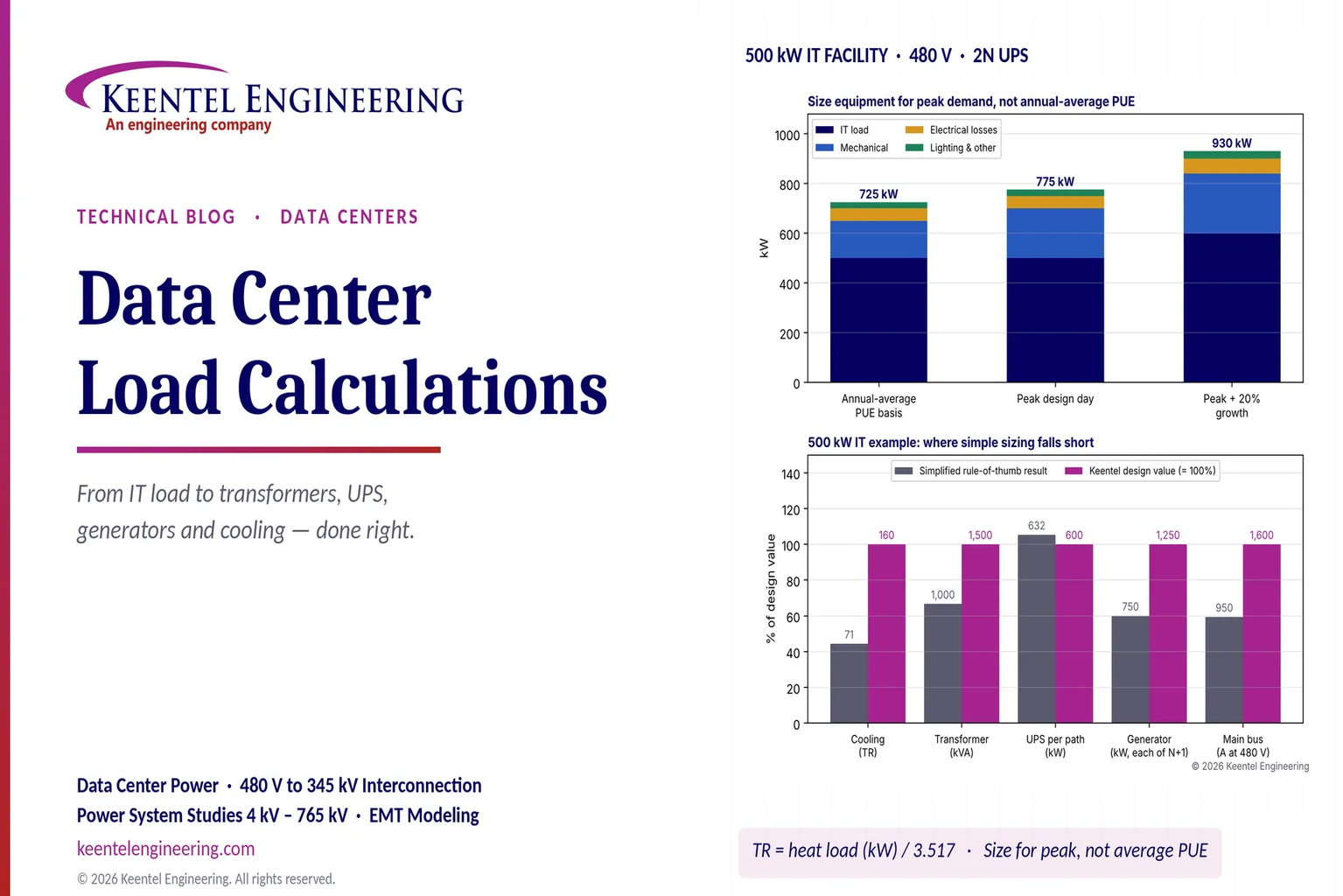
Learn data center electrical load calculations, including IT demand, PUE, UPS and generator sizing, cooling loads, redundancy, and worked US examples.
By SANDIP R PATEL
•
October 20, 2026
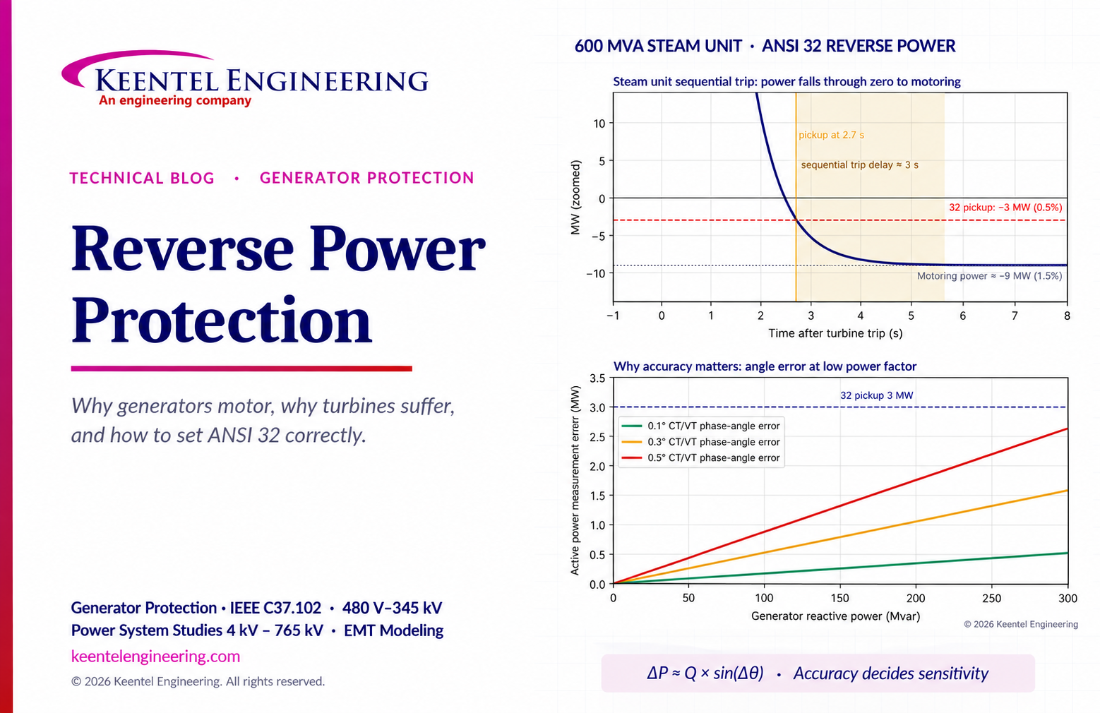
Learn reverse power protection (ANSI 32), generator motoring, relay pickup settings, time delays, sequential tripping and testing for US power plants.

By Team 2 Dexora
•
October 20, 2026
Explore grounding system testing with Keentel Engineering. Learn IEEE 80/81 methods, soil resistivity, ground resistance, and touch and step voltage safety.

By SANDIP R PATEL
•
October 13, 2026
Plan data center capacity with land screening, MW-per-acre estimates, grid power availability and interconnection feasibility studies from Keentel Engineering.





