
A Coordinated Electric System Interconnection Review—the utility’s deep-dive on technical and cost impacts of your project.
Challenge: Frequent false tripping using conventional electromechanical relays
Solution: SEL-487E integration with multi-terminal differential protection and dynamic inrush restraint
Result: 90% reduction in false trips, saving over $250,000 in downtime
ERCOT enforces all of the above through simulation, which means your model is your compliance case. The bar is now high:
- Whole-facility scope. The model must represent everything the IT load, the UPS and power conversion, the cooling plant, the protection and control systems in formats compatible with ERCOT's study platforms (PSS/E, PSCAD, TSAT).
- Real control loops, not approximations. Generic textbook representations are unacceptable. The model must capture the actual inner control behavior of your power electronics.
- Hardware-validated converter models. For electronic loads, the PSCAD model must be benchmarked against actual hardware testing including voltage ride-through and subsynchronous response. A model assembled from standard PSCAD library blocks fails by definition, because a generic block has never been tested against your vendor's hardware. The good news: validation is a hardware-type test, so results for a given converter product are reusable across every facility that uses it.
- Format migration. Facilities that previously submitted the older composite load model (CMLD) format must transition to EPRI's PERC1 format.
- Three checkpoints. Models are reviewed before the stability study begins (no model, no study), before each quarterly stability assessment, and for electronic loads one final time before energization, when you must submit as-built models with a documented comparison against the previously studied data and a sworn attestation that the model matches actual field settings. ERCOT's review takes 10 business days, extendable by 20 put it on your critical path.
- A living obligation. Change your technology, controls, or relay settings in a way that affects ride-through including converting a crypto mining site to an AI data center — and you've triggered a new interconnection study, even if your megawatts don't change.
| Parameter | Detail |
|---|---|
| System | 230 kV / 138 kV transmission corridors, wind and wet-snow icing exposure |
| Data basis | 15 years of minute-resolution forced-outage records + regional weather observations |
| Core methods | Event grouping, MVA performance curves, time-to-95%-restore, area outage rate curves, fragility modeling, rerun-history benefits, exceedance and log-domain risk metrics |
| Headline result | ≈85% of maximum resilience benefit at 60% of original capital; worst-event restoration window cut from 11 days to 5 in rerun-history terms |
| Decision supported | Capital portfolio selection; resilience plan filing; post-investment verification framework |
| System / Topic | Governing Standard(s) | What It Controls |
|---|---|---|
| Overall plant electrical distribution | IEEE 141 (Red Book); IEEE 666 | Distribution architecture, voltage selection, design of generating station auxiliary service systems |
| Power system studies | IEEE 399 (Brown Book); IEEE 551 | Load flow, symmetrical/asymmetrical short circuit, motor starting methodologies down to the lowest LV panelboard |
| Protection & coordination | IEEE 242 (Buff Book); IEEE 3004.5; IEEE C37 series | Generator relaying (21, 59N, 87G), time-current coordination, selective clearing between LV and MV tiers |
| GSU / UAT / SST transformers | IEEE C57.12.00 and C57 family | Transformer ratings, impedance, testing, loading |
| HV switchyard breakers | IEEE C37.06 | AC high-voltage circuit breaker preferred ratings |
| MV switchgear (13.8 kV) | IEEE C37.20.2; IEEE C37.20.7 | Metal-clad construction, compartmentalization, vacuum breakers; arc-resistant design with plenum venting |
| MV cable | UL 1072; ICEA S-93-639 (NEMA WC 74) | Type MV-105 shielded cable, 133% insulation level for HRG systems |
| LV switchgear (480 V) | IEEE C37.13; UL 1558 | Metal-enclosed LV power circuit breaker switchgear to 635 V, draw-out ACBs with electronic trip units |
| Motor control centers | UL 845; NEMA ICS 18 | LV-MCC construction, MCCB/MCP protection for motors under ~200 HP |
| Motors | NEMA MG-1 | Motor performance, starting characteristics, service factors |
| DC & battery systems | IEEE 485; IEEE 946 | Lead-acid battery sizing (125/250 VDC), DC auxiliary system design |
| Grounding | IEEE 80; IEEE 142 (Green Book) | Ground grid step/touch potential limits; system grounding including high-resistance grounding |
| Lightning protection | IEEE 998 | Direct-stroke shielding of switchyard and outdoor generator structures |
| Arc flash & electrical safety | IEEE 1584; NFPA 70E | Incident energy calculation; worker safety boundaries and PPE |
| Fire protection | NFPA 850 | Fire protection and risk management for combustion turbine generating plants |
| Installation code | NEC (NFPA 70); NESC | Wiring methods inside the plant fence; overhead/outdoor clearances at the switchyard |
| Interconnection & compliance | FERC LGIP; NERC MOD-025/026/027, PRC-019/024/029, FAC-008 | Interconnection process, model validation, protection/ride-through coordination, facility ratings |
| IFC / Construction Deliverable | Purpose |
|---|---|
| Stamped IFC packages | Legal basis for construction; P.E. responsible charge |
| Final relay settings & TCCs | Protection as-installed matches the coordination study |
| Calculation archive | Owner records; NERC audit evidence trail |
| Commissioning procedures | Safe, sequenced energization; MOD field testing |
| Construction support | RFIs, field changes, FAT/SAT witness |
| As-builts & model handoff | Operating baseline; future study currency |
| Metric | Outcome |
|---|---|
| Defects found pre-occupancy | Three topology defects and one settings-mismatch family corrected before load migration; the shared-switchboard defect alone would have invalidated the concurrently-maintainable claim on day one |
| IST findings | Fourteen additional discrepancies surfaced under scenario testing (control logic, alarm mapping, one generator sequencing fault) — all closed before handover instead of during operations |
| Black-building test | Passed on second execution; the first attempt exposed the generator sequencing fault under true block load, exactly the failure the compressed plan would never have found |
| Handover quality | Operations team certified on the actual failure scenarios; corrected EOPs and settings documentation delivered as controlled documents |
| Business outcome | Occupancy proceeded three weeks behind the original date — against an independent estimate that the uncorrected sequencing fault carried a high probability of a full facility outage within the first year |
Part 2 — Frequently Asked Questions: Large Load Interconnection
| Contact | Details |
|---|---|
| Headquarters | 400 N Ashley Dr STE 2600, Tampa, FL 33602 |
| Phone | (813) 389-7871 |
| contact@keentelengineering.com | |
| Florida Firm Registration | No. 36853 |
| Additional Offices | Austin, TX • Sacramento, CA • Baltimore, MD |
| Who | Acronym | Plain-English Role |
|---|---|---|
| ERCOT | — | The grid's air traffic controller. It doesn't own power lines or plants; it directs the flow of electricity across most of Texas and referees the admission process for new generators. |
| Interconnecting Entity | IE | You — the developer or owner trying to connect a new plant (or significantly modify an existing one). You file the application and drive the process. |
| Resource Entity | RE | The registered owner/operator of the generator once it becomes an official market participant. Often the same company as the IE, wearing a different hat. |
| Qualified Scheduling Entity | QSE | Your plant's voice on the grid. The QSE handles round-the-clock communications with ERCOT — telemetry, schedules, dispatch instructions. Every generator must have one. |
| Transmission Service Provider | TSP | The utility that owns the wires and substation you'll connect to. The TSP runs your detailed study, builds the connection facilities, and signs your interconnection contract. |
| RIOO-IS | — | ERCOT's online portal where the whole process lives — applications, documents, status tracking, and checklists all flow through it. |
| Who | Acronym | Plain-English Role |
|---|---|---|
| ERCOT | — | The grid's air traffic controller. It doesn't own power lines or plants; it directs the flow of electricity across most of Texas and referees the admission process for new generators. |
| Interconnecting Entity | IE | You — the developer or owner trying to connect a new plant (or significantly modify an existing one). You file the application and drive the process. |
| Resource Entity | RE | The registered owner/operator of the generator once it becomes an official market participant. Often the same company as the IE, wearing a different hat. |
| Qualified Scheduling Entity | QSE | Your plant's voice on the grid. The QSE handles round-the-clock communications with ERCOT — telemetry, schedules, dispatch instructions. Every generator must have one. |
| Transmission Service Provider | TSP | The utility that owns the wires and substation you'll connect to. The TSP runs your detailed study, builds the connection facilities, and signs your interconnection contract. |
| RIOO-IS | — | ERCOT's online portal where the whole process lives — applications, documents, status tracking, and checklists all flow through it. |
| Who | Acronym | Plain-English Role |
|---|---|---|
| ERCOT | — | The grid's air traffic controller. It doesn't own power lines or plants; it directs the flow of electricity across most of Texas and referees the admission process for new generators. |
| Interconnecting Entity | IE | You — the developer or owner trying to connect a new plant (or significantly modify an existing one). You file the application and drive the process. |
| Resource Entity | RE | The registered owner/operator of the generator once it becomes an official market participant. Often the same company as the IE, wearing a different hat. |
| Qualified Scheduling Entity | QSE | Your plant's voice on the grid. The QSE handles round-the-clock communications with ERCOT — telemetry, schedules, dispatch instructions. Every generator must have one. |
| Transmission Service Provider | TSP | The utility that owns the wires and substation you'll connect to. The TSP runs your detailed study, builds the connection facilities, and signs your interconnection contract. |
| RIOO-IS | — | ERCOT's online portal where the whole process lives — applications, documents, status tracking, and checklists all flow through it. |
| Who | Acronym | Plain-English Role |
|---|---|---|
| ERCOT | — | The grid's air traffic controller. It doesn't own power lines or plants; it directs the flow of electricity across most of Texas and referees the admission process for new generators. |
| Interconnecting Entity | IE | You — the developer or owner trying to connect a new plant (or significantly modify an existing one). You file the application and drive the process. |
| Resource Entity | RE | The registered owner/operator of the generator once it becomes an official market participant. Often the same company as the IE, wearing a different hat. |
| Qualified Scheduling Entity | QSE | Your plant's voice on the grid. The QSE handles round-the-clock communications with ERCOT — telemetry, schedules, dispatch instructions. Every generator must have one. |
| Transmission Service Provider | TSP | The utility that owns the wires and substation you'll connect to. The TSP runs your detailed study, builds the connection facilities, and signs your interconnection contract. |
| RIOO-IS | — | ERCOT's online portal where the whole process lives — applications, documents, status tracking, and checklists all flow through it. |
| Who | Acronym | Plain-English Role |
|---|---|---|
| ERCOT | — | The grid's air traffic controller. It doesn't own power lines or plants; it directs the flow of electricity across most of Texas and referees the admission process for new generators. |
| Interconnecting Entity | IE | You — the developer or owner trying to connect a new plant (or significantly modify an existing one). You file the application and drive the process. |
| Resource Entity | RE | The registered owner/operator of the generator once it becomes an official market participant. Often the same company as the IE, wearing a different hat. |
| Qualified Scheduling Entity | QSE | Your plant's voice on the grid. The QSE handles round-the-clock communications with ERCOT — telemetry, schedules, dispatch instructions. Every generator must have one. |
| Transmission Service Provider | TSP | The utility that owns the wires and substation you'll connect to. The TSP runs your detailed study, builds the connection facilities, and signs your interconnection contract. |
| RIOO-IS | — | ERCOT's online portal where the whole process lives — applications, documents, status tracking, and checklists all flow through it. |
| Who | Acronym | Plain-English Role |
|---|---|---|
| ERCOT | — | The grid's air traffic controller. It doesn't own power lines or plants; it directs the flow of electricity across most of Texas and referees the admission process for new generators. |
| Interconnecting Entity | IE | You — the developer or owner trying to connect a new plant (or significantly modify an existing one). You file the application and drive the process. |
| Resource Entity | RE | The registered owner/operator of the generator once it becomes an official market participant. Often the same company as the IE, wearing a different hat. |
| Qualified Scheduling Entity | QSE | Your plant's voice on the grid. The QSE handles round-the-clock communications with ERCOT — telemetry, schedules, dispatch instructions. Every generator must have one. |
| Transmission Service Provider | TSP | The utility that owns the wires and substation you'll connect to. The TSP runs your detailed study, builds the connection facilities, and signs your interconnection contract. |
| RIOO-IS | — | ERCOT's online portal where the whole process lives — applications, documents, status tracking, and checklists all flow through it. |
| Who | Acronym | Plain-English Role |
|---|---|---|
| ERCOT | — | The grid's air traffic controller. It doesn't own power lines or plants; it directs the flow of electricity across most of Texas and referees the admission process for new generators. |
| Interconnecting Entity | IE | You — the developer or owner trying to connect a new plant (or significantly modify an existing one). You file the application and drive the process. |
| Resource Entity | RE | The registered owner/operator of the generator once it becomes an official market participant. Often the same company as the IE, wearing a different hat. |
| Qualified Scheduling Entity | QSE | Your plant's voice on the grid. The QSE handles round-the-clock communications with ERCOT — telemetry, schedules, dispatch instructions. Every generator must have one. |
| Transmission Service Provider | TSP | The utility that owns the wires and substation you'll connect to. The TSP runs your detailed study, builds the connection facilities, and signs your interconnection contract. |
| RIOO-IS | — | ERCOT's online portal where the whole process lives — applications, documents, status tracking, and checklists all flow through it. |
Protection Design
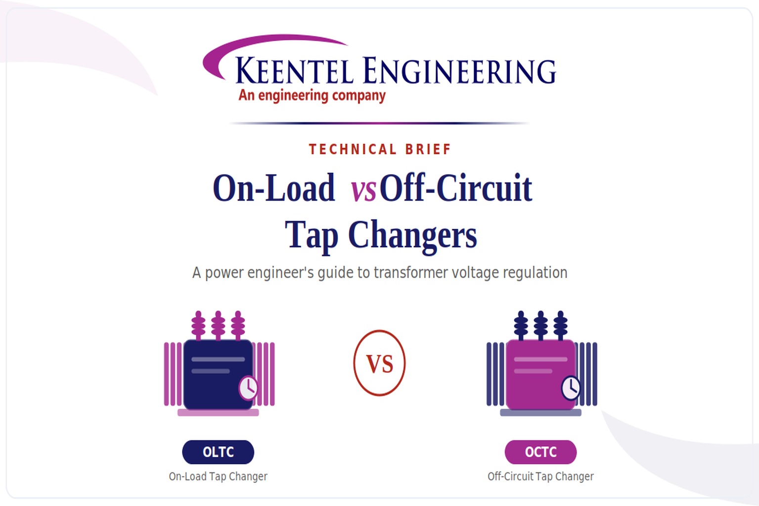
On-Load vs Off-Circuit Tap Changers
Jul 29, 2026 | Blog
A power engineer's guide to transformer voltage regulation, selection, standards, and lifecycle care
Voltage is the quiet variable that decides whether a power system runs efficiently or wears itself out. Push it too high and insulation ages faster, iron losses climb, and sensitive loads trip. Let it sag and motors overheat, transformers draw more current, and power quality complaints stack up. The transformer tap changer is the single most important device for keeping that variable inside its acceptable band. It does so by adjusting the transformer's turns ratio in small, discrete steps, trimming the secondary voltage up or down as source conditions and load demand shift through the day.
Two families of tap changer do this job, and choosing between them is one of the more consequential decisions an engineer makes when specifying or refurbishing a transformer. The On-Load Tap Changer (OLTC) regulates voltage continuously while the transformer stays energized and fully loaded. The Off-Circuit Tap Changer (OCTC) — often called an Off-Load Tap Changer or, more precisely in modern standards, a De-Energized Tap Changer (DETC) — changes the ratio only when the transformer has been switched out and isolated. The infographic that prompted this brief captures the headline difference well; the purpose of the pages that follow is to give plant and utility engineers the depth behind that headline: how each device actually works, where each belongs, what the governing standards require, how they fail, and how to keep them healthy across a forty-year asset life.
At a glance
An OLTC makes-before-breaks under load using a diverter switch and transition impedance, so voltage can be regulated without interrupting supply. An OCTC/DETC is a simple selector that must never be operated while the transformer is energized. OLTCs suit transmission and large distribution transformers where uninterrupted regulation matters; OCTCs suit distribution and industrial units where the ratio is set once and rarely touched.
1. The fundamentals: turns ratio and voltage regulation
A transformer's output voltage is fixed by the ratio of its primary to secondary turns. If either winding's effective turn count can be altered, the ratio changes and, with it, the output voltage for a given input. Tap changers exploit this by bringing out several connection points — taps — along one winding, usually the high-voltage winding. Selecting a different tap adds or subtracts turns and shifts the ratio in defined percentage steps, most commonly ±1.25% or ±1.67% per step across a range such as ±10% or ±15%.
Taps are placed on the high-voltage winding for two practical reasons. The HV winding carries lower current, so the tap contacts handle a smaller duty and can be made physically smaller. It also tends to be the outer winding, which makes the tap leads easier to route to the changer. The number of usable positions is a design choice: a 17-position changer giving ±8 steps of 1.25% delivers a ±10% regulating range, which covers the great majority of grid and industrial requirements.
The reason a tap changer is needed at all comes down to the fact that neither the source nor the load holds still. Upstream, grid voltage rises overnight when demand falls and dips during peak periods; distributed generation can push local voltage up unexpectedly. Downstream, the voltage drop across the transformer and feeders swings with load. Without regulation the customer-end voltage would wander outside statutory limits. The question is never whether to regulate, but whether regulation must happen live — which is exactly where the OLTC and OCTC part ways.
2. The On-Load Tap Changer (OLTC) in depth
An OLTC changes taps without interrupting load current. That sounds simple until you consider the constraint: you can never open-circuit a current-carrying winding (the resulting arc and overvoltage would be destructive), and you can never directly short two adjacent taps (the circulating current driven by the inter-tap voltage would be enormous). The OLTC's entire design exists to move between taps while satisfying both rules simultaneously. It does this with a make-before-break sequence and a transition impedance that momentarily bridges the two taps, limiting the circulating current during the fraction of a second both are connected.
2.1 Selector switch and diverter switch
A conventional OLTC separates its work between two mechanisms. The tap selector pre-selects the next tap while it carries no switching arc — it moves the standby contact onto the target tap ahead of the actual transfer. The diverter switch (also called the arcing switch) then performs the fast transfer of load current from the running tap to the pre-selected one, breaking the arc as it goes. Separating selection from arcing means the slow, precise positioning happens without arcing, and the arcing happens in a fast, spring-driven snap action that the operator's motor drive cannot slow down or stall mid-transfer. The stored-energy accumulator that fires the diverter is why an OLTC transfer completes in tens of milliseconds regardless of how sluggishly the motor turns.
Because arcing is confined to the diverter switch, the diverter is where contact erosion, oil carbonization, and maintenance attention concentrate. In many designs the diverter operates in its own oil compartment, sealed off from the main tank so that the by-products of switching — carbon, dissolved gases, metal particles — do not contaminate the main insulating oil or corrupt the transformer's own dissolved-gas analysis. This separation is a detail worth remembering, because it shapes both the maintenance regime and the diagnostics.
2.2 Resistor-type versus reactor-type transition
The transition impedance that bridges adjacent taps is either a resistor or a reactor, and the choice defines two engineering traditions. Resistor-type OLTCs, dominant in European practice and on most transmission-class transformers worldwide, keep the resistors in circuit only for the few milliseconds of transfer. The resistors are compact and cheap, but because they cannot dissipate heat for long, the transition must be fast — hence the spring-driven diverter. Reactor-type OLTCs, historically common in North American distribution practice, use a center-tapped preventive autotransformer (the reactor) that can carry current continuously. This lets the changer rest on a bridging position between two taps, effectively doubling the number of voltage steps, and it tolerates slower switching — but the reactor is bulky and adds load loss.
For an engineer specifying a new unit, the practical takeaways are that resistor-type changers are lighter, more efficient, and standard on power transformers, while reactor-type changers are rugged and forgiving on distribution feeders with very high operating counts. The maintenance philosophies differ accordingly, and spares are not interchangeable, so it matters to know which tradition a given fleet follows.
2.3 Vacuum tap changers
The most significant OLTC advance of the past two decades is the move from oil-arcing to vacuum interrupter diverter switches. In a vacuum-type OLTC the arc is drawn and extinguished inside a sealed vacuum bottle rather than in the surrounding oil. Because the arc never contacts the oil, the oil does not carbonize, contact erosion falls dramatically, and maintenance intervals stretch from the traditional interval to intervals measured by hundreds of thousands of operations or many years. Vacuum changers have become the default for new high-duty applications — notably those with heavy renewable-driven cycling — and are a common retrofit target for aging oil-type units. The trade-off is a higher purchase price and the need to verify vacuum-bottle integrity, since a failed bottle removes the arc-quenching function entirely.
Engineer's note where OLTC value is highest
The economic case for an OLTC strengthens sharply wherever voltage must stay in band during operation: grid intertie and generator step-up transformers, industrial supplies feeding voltage-sensitive process loads, arc-furnace and rolling-mill supplies, and any feeder with large distributed generation that swings local voltage. On these duties the cost of an outage to re-tap an OCTC — or the cost of running out of regulation range — dwarfs the OLTC's price premium.
3. The Off-Circuit / De-Energized Tap Changer (OCTC) in depth
The OCTC — the term the infographic uses — is the same conceptual device stripped of the ability to switch under load. It is a selector that connects the winding to one of several taps, and it must only be moved when the transformer is de-energized and, in safe practice, isolated and earthed on both sides. Because it never interrupts current, it needs no diverter switch, no transition impedance, and no stored-energy drive. The result is a mechanism of elegant simplicity: often little more than a rotary contact assembly operated by an external hand-wheel or a shaft brought through the tank wall, sometimes lockable to prevent operation under load.
Modern standards increasingly prefer the label De-Energized Tap Changer (DETC) precisely because "off-load" has caused dangerous confusion — an operator hearing "off-load" has been known to interpret it as "safe to switch when lightly loaded," which it emphatically is not.
Operating a DETC under load, even at low current, can weld the contacts, draw a sustained arc inside the tank, and in the worst case initiate a transformer fire. Any procedure Keentel writes for a DETC begins with confirmed isolation, not reduced load.
The DETC's role is to set a nominal ratio that matches the transformer to its actual point on the network — for instance, trimming for a feeder that consistently runs a few percent high or low, or re-matching a transformer after it is relocated to a different part of the grid. Once set at commissioning it may never be touched again for the life of the unit, or perhaps adjusted seasonally where a utility runs a summer and a winter setting. Its simplicity is its virtue: fewer moving parts mean fewer failure modes, negligible maintenance, and a lower purchase price, which is exactly why the overwhelming majority of distribution transformers use one.
Safety caution
A DETC/OCTC must never be operated while the transformer is energized. "Off-load" does not mean "low load" — it means de-energized and isolated. Establishing dead, isolated, and earthed conditions before touching the mechanism is the non-negotiable first step of every tap-change procedure on these units.
4. Head-to-head comparison
The table below consolidates the operational, commercial, and lifecycle differences that most often drive a specification decision. Read it not as a verdict but as a map: the right device is always the one whose strengths match the duty in front of you.
| Attribute | OLTC (On-Load Tap Changer) | OCTC / DETC (Off-Circuit Tap Changer) |
|---|---|---|
| Operates under load | Yes — regulates while energized and carrying current | No — transformer must be de-energized and isolated |
| Primary function | Continuous, automatic voltage regulation | One-time or seasonal ratio setting |
| Switching element | Selector + diverter switch with transition impedance | Simple make-before-break selector, no arc interruption |
| Mechanism complexity | High — motor drive, diverter, transition resistors/reactor | Low — hand-wheel or simple drive |
| Typical location | Power / transmission & large distribution transformers | Distribution & industrial transformers |
| Operations per year | Thousands to tens of thousands | A few, or none after commissioning |
| Relative capital cost | High | Low |
| Maintenance demand | Periodic contact & oil service, condition monitoring | Minimal; occasional contact re-torque |
| Governing standards | IEEE C57.131, IEC/IEEE 60214-1 & -2 | Covered under transformer standards & 60214 series |
| Downtime to change tap | None | Outage required |
5. How to choose: a selection framework for engineers
Reduced to its essence, the choice turns on a single question: does the voltage need to be corrected while the transformer is in service? If the answer is yes, an OLTC is not a luxury but a requirement, and the remaining questions are about sizing and technology. If the answer is no — if a fixed ratio set at commissioning will hold the voltage acceptably — then an OCTC is the lighter, cheaper, more reliable answer. Around that core, Keentel evaluates six factors when advising on a specification:
- Regulation duty. How far and how often must the voltage move? Continuous automatic correction against a swinging source or load points to an OLTC; a one-time trim points to an OCTC.
- Load criticality and outage tolerance. If the load cannot tolerate the outage required to re-tap, the OLTC's live-switching capability pays for itself the first time regulation is needed.
- Operating frequency. Feeders with heavy daily cycling — especially those hosting solar or wind — may demand tens of thousands of operations a year, which steers the choice toward a vacuum OLTC sized for that duty.
- Position in the network. Transmission and generator step-up duty almost always justifies an OLTC; radial distribution and industrial step-down duty often does not.
- Total cost of ownership. The comparison is never purchase price alone. It weighs the OLTC's maintenance and monitoring against the OCTC's outage costs and the risk of being caught with the wrong ratio.
- Future flexibility. Rising DER penetration is turning many formerly quiet feeders into voltage-volatile ones. Where growth is likely, specifying an OLTC — or at least a transformer that can be retrofitted with one — hedges against a costly change later.
6. Standards and compliance
Tap changers are governed by a mature and internationally harmonized body of standards, and specifying to them is what separates a defensible procurement from a risky one. The principal references an engineer should know are:
- IEEE C57.131 — Standard Requirements and Test Methods for Tap-Changers. This is the North American benchmark for performance and type testing of load tap changers, covering switching duty, short-circuit capability, mechanical and electrical endurance, and transition-impedance requirements.
- IEC/IEEE 60214-1 — the design and type-test standard for tap changers, harmonizing the former IEC 60214 with IEEE practice. It defines the tests a tap changer must pass to be qualified.
- IEC/IEEE 60214-2 — the application guide. Where Part 1 tells you whether a tap changer is fit to be built, Part 2 tells you how to apply it correctly to a given transformer, including selection of transition impedance, insulation coordination, and duty matching.
- IEEE C57.12.00 and IEC 60076 series — the parent transformer standards, which set the context (temperature rise, insulation levels, short-circuit withstand) within which the tap changer must operate.
For the engineer the standards matter in three concrete ways. They define the type tests that qualify a design, so a compliant unit arrives with a documented switching and endurance capability. They define routine tests performed on every unit, so a specific serial number is verified before it ships. And they underpin the maintenance and diagnostic regime, giving the reference values against which contact resistance, timing, and oil condition are judged in service. Keentel specifies and audits against these documents rather than against a manufacturer's brochure, because the standard is the neutral ground on which supplier claims are tested.
7. Maintenance, testing, and condition monitoring
An OCTC asks very little of a maintenance program. Because it never arcs, its contacts erode only from the occasional operation, and its main enemy is the slow oxidation and pitting that comes from sitting on one position for years — a low-current "coking" that raises contact resistance and generates local heat. The standard remedy is to exercise the changer through its full range during a scheduled transformer outage, wiping the contacts clean, and to check contact resistance before returning to service. Beyond that, the OCTC largely looks after itself.
An OLTC is the opposite: it is the most mechanically active and most failure-prone component of a power transformer, and industry studies consistently attribute a large share of transformer failures to the tap changer. Its maintenance is correspondingly structured, and it rewards a shift from fixed-interval servicing to condition-based intervention. The pillars of a modern OLTC maintenance and diagnostic program are:
7.1 Oil condition and dissolved-gas analysis (DGA)
The diverter compartment oil carbonizes with every arc, so its dielectric strength falls and its gas content rises as a normal consequence of duty. Sampling that oil and interpreting the dissolved gases — while carefully distinguishing the expected arcing signature of an OLTC from a genuine fault — is a primary health indicator. Crucially, because the diverter oil is separate from the main-tank oil in most designs, OLTC DGA is a distinct exercise from transformer DGA; conflating the two samples is a classic diagnostic error that either masks a real fault or raises a false alarm.
7.2 Dynamic resistance measurement (DRM)
DRM records the resistance and current through the tap changer during an actual transfer, capturing the make-before-break sequence as a waveform. A clean trace shows the transition impedance entering and leaving circuit smoothly with no open-circuit "spikes"; a degraded trace reveals worn or misaligned contacts, incorrect timing, or a transition resistor drifting out of value — often long before the fault would show up any other way. DRM has become the workhorse diagnostic for OLTC contact and timing health.
7.3 Motor-drive and timing checks
Because the diverter fires from a stored-energy spring, the motor-drive mechanism, its limit switches, and the synchronization between selector and diverter all bear watching. Monitoring drive motor current during operation reveals a stiffening gearbox or a binding mechanism; timing measurement confirms the diverter is still snapping over within specification.
7.4 Continuous online monitoring
The trend across the industry — and a core part of the Industry 4.0 story for substations — is toward permanent OLTC monitoring: tracking operation counts, motor torque or current signature, contact temperature differential relative to the main tank, and vibro-acoustic signatures of each switching event. These systems let an asset owner move from calendar-based overhauls to intervention driven by actual wear, deferring unnecessary outages while catching genuine degradation early. For a fleet operator the payoff is both fewer surprise failures and fewer needless entries into a healthy tap changer.
Rule of thumb
If a transformer is going to fail at its tap changer — and statistically the tap changer is the most likely mechanical culprit — the warning almost always appears first in one of three places: the diverter oil's gas and dielectric trend, the DRM contact-and-timing trace, or the motor-drive current signature. A program that watches those three watches most of the risk.
8. Common failure modes
Understanding how tap changers fail sharpens both specification and maintenance. The recurring failure modes Keentel investigates include:
- Contact wear and coking on the OCTC. Long dwell on one position lets a resistive, high-temperature film build on the contacts. It is benign until the transformer is finally re-tapped and the film prevents proper contact — an avoidable failure caught by periodic exercising.
- Diverter contact erosion on the OLTC. Every live transfer erodes the arcing contacts. Left past their wear limit they raise resistance, generate heat, and eventually fail to transfer cleanly. This is the wear DRM is designed to trend.
- Transition resistor failure. A cracked or open transition resistor turns a controlled transfer into an open-circuit event across a tap, with severe arcing. Type-tested designs and DRM screening guard against it.
- Coking and oil degradation. Carbon from arcing accumulates in the diverter compartment, lowering dielectric strength and, if neglected, bridging insulation. It is the reason the diverter oil is serviced on its own schedule.
- Mechanism and motor-drive faults. A stalled drive, a slipped shaft, or a mis-set limit switch can leave a changer stuck between taps — an open-circuit or bridging condition that is one of the more dangerous OLTC failures.
- Operation of a DETC under load. The catastrophic human-factors failure: an energized de-energized-only changer arcing internally. It is prevented by procedure, interlocks, and clear labeling, not by hardware alone.
9. Where the technology is heading
Three forces are reshaping tap-changer engineering. The first is the displacement of oil-arcing by vacuum switching, which cuts maintenance dramatically and suits the high operation counts that renewables impose. The second is distributed energy resource growth, which is converting quiet radial feeders into bidirectional, voltage-volatile circuits and pushing OLTC capability deeper into the distribution network than it has traditionally sat. The third is digital condition monitoring, which turns the tap changer from a black box serviced on a calendar into a continuously observed asset whose interventions are timed by data.
For an asset owner these trends converge on a single strategic message: the tap changer is no longer a set-and-forget accessory. It is a decisive reliability component whose selection, monitoring, and lifecycle planning deserve engineering attention proportional to its risk. That is the lens Keentel brings to every transformer study.
10. How Keentel Engineering supports your assets
Keentel Engineering is an independent electrical engineering consultancy. We do not sell tap changers, which means our advice on selection, condition, and lifecycle is grounded in the standards and in your operating data rather than in a product line. Across the tap-changer lifecycle we support clients with:
- Specification and selection studies — matching OLTC or OCTC technology, regulating range, and step size to your network duty and growth outlook, written to IEEE C57.131 and IEC/IEEE 60214.
- Condition assessment — DGA interpretation, DRM testing, contact-resistance and timing analysis, and end-of-life or refurbishment recommendations for in-service units.
- Monitoring strategy — designing online monitoring and moving fleets from calendar-based to condition-based maintenance.
- Failure investigation — independent root-cause analysis when a tap changer has misoperated or failed.
Standards and procedure development — safe switching procedures, interlock reviews, and specification audits against the governing standards.
Case studies
The following three case studies are drawn from Keentel Engineering engagements. Client names, locations, and identifying details have been withheld or altered to protect commercial confidentiality; the technical narratives and outcomes are representative of the work performed.
All projects anonymized — confidential.
Case study 1 Recurrent OLTC misoperation on a 132/33 kV grid transformer
Sector: Transmission / distribution utility
Asset: 63 MVA, 132/33 kV power transformer with resistor-type OLTC
Engagement: Root-cause investigation and remediation plan
The challenge
A regional utility approached Keentel after a grid transformer suffered two unexplained voltage-regulation disturbances within eight months. On both occasions the OLTC appeared to "hunt" — stepping repeatedly and failing to settle — and the second event tripped the transformer on a Buchholz gas alarm. The asset was mid-life and strategically important, feeding a 33 kV network with no ready alternative supply, so the utility was under pressure to decide quickly between continued operation, refurbishment, and replacement. The internal team suspected the automatic voltage control relay; the OEM pointed to oil condition. The two explanations implied very different remedies and costs.
The Keentel approach
Keentel treated the disagreement as a symptom of incomplete evidence and ran an independent, standards-referenced assessment rather than adopting either party's theory. The investigation combined dynamic resistance measurement across the full tap range, separate DGA on the diverter compartment oil and the main-tank oil, an audit of the automatic voltage control settings and inter-tap timing, and a review of the operation-counter history against the changer's rated endurance. Reading the diverter DGA independently of the main-tank DGA was decisive: the main tank was healthy, while the diverter oil showed an arcing signature well above the expected level for the recorded operation count.
The DRM traces then localized the problem. On two adjacent tap positions the transfer showed a momentary resistance excursion consistent with a worn diverter contact set combined with a transition resistor drifting high. The "hunting" the operators saw was the voltage control relay correctly commanding steps, but the degraded diverter was producing an inconsistent voltage result, so the control never found a stable position — a control-versus-mechanism interaction that neither single-discipline theory had captured.
The outcome
Keentel recommended a targeted diverter-switch overhaul with contact and transition-resistor replacement, a diverter oil change, and a re-commissioning DRM test to confirm the transfer signature before return to service — a fraction of the cost of the replacement the utility had begun to budget for. The voltage control settings were left essentially unchanged, sparing an unnecessary and misdirected relay project. Following the overhaul the transformer returned to stable regulation with no further hunting events, and the utility adopted Keentel's recommendation to add periodic DRM screening to its grid-transformer maintenance standard so that comparable degradation would be caught by trend rather than by trip.
Case study 2 DETC contact failure at re-energization of an industrial transformer
Sector: Heavy manufacturing / industrial plant
Asset: 20 MVA, 33/11 kV transformer with de-energized (off-circuit) tap changer
Engagement: Failure investigation and preventive-maintenance redesign
The challenge
During a planned shutdown, a manufacturing site adjusted the off-circuit tap on a main intake transformer to correct a persistently low 11 kV busbar voltage that had been stressing plant motors. When the transformer was re-energized after the tap change, it drew abnormal magnetizing behavior and tripped, and subsequent testing showed a high and unstable contact resistance on the newly selected tap. Production was held pending a diagnosis, and the plant's engineering team was unsure whether the fault lay in the tap change they had made, in the transformer winding, or in the switchgear — an ambiguity that risked either a premature winding condemnation or an unsafe return to service.
The Keentel approach
Keentel's first action was to bound the problem to the tap changer and exonerate the winding, using winding-resistance and turns-ratio measurements across all tap positions together with insulation diagnostics. The pattern was unambiguous: the winding and insulation were sound, but contact resistance was high specifically on the positions that had not been used for years, and worst on the one just selected. This was textbook coking — a resistive film that had built up over a long dwell on the original position, present in latent form on the idle taps, and exposed the moment the changer was moved onto one of them.
The remedy on site was to exercise the de-energized changer repeatedly through its full range to wipe the contacts, followed by contact-resistance verification on every position before re-energization. Keentel supervised the procedure under strict confirmation that the transformer was dead, isolated, and earthed — reinforcing that an off-circuit changer's contacts are only ever to be worked with the unit de-energized. Once the resistance had fallen to an acceptable and stable value across the range, the transformer was returned to service on the corrected tap without recurrence.
The outcome
Beyond restoring production, Keentel rewrote the site's transformer maintenance procedure to require periodic exercising of every off-circuit tap changer during shutdowns — a near-zero-cost measure that prevents exactly this failure by never letting a coked film mature undisturbed. The investigation also corrected a latent safety gap: the previous procedure had described the changer as "off-load," which the team had informally read as permitting adjustment under light load. Keentel's revised procedure and labeling made de-energized isolation an explicit, verified prerequisite. The client reported that the same fix, applied across its transformer fleet, surfaced two further coked changers before they could fail in service.
Case study 3 — Voltage volatility on a solar-rich distribution feeder
Sector: Distribution utility with high DER penetration
Asset: Feeder transformer fleet; candidate 15 MVA units for OLTC upgrade
Engagement: Voltage-regulation and tap-changer strategy study
The challenge
A distribution utility was fielding rising numbers of voltage-quality complaints on several feeders that had absorbed substantial rooftop and small-scale solar generation. Where the feeders had once carried power one way and drooped predictably under load, midday solar export was now pushing voltage above statutory limits, while evening demand pulled it low — a daily swing the existing off-circuit-tapped transformers, set once at a fixed ratio, simply could not follow. The utility needed to know whether to persevere with fixed taps and other measures, or invest in on-load regulation, and if so, on which units and with what technology.
The Keentel approach
Keentel ran a voltage-regulation study grounded in the feeders' actual behavior rather than in nameplate assumptions. Using logged voltage and load profiles, and modeling the solar export against demand across the day, the study quantified how far and how often the voltage left band on each candidate feeder and how many regulating operations per year an on-load solution would face. That operation-count estimate proved central: the daily bidirectional swing implied tens of thousands of operations a year, far beyond what a conventional oil-arcing OLTC would service economically. The analysis pointed clearly toward vacuum-type OLTCs, whose extended maintenance intervals suit exactly this high-cycling duty, on the specific transformers feeding the worst-affected sections.
The study weighed the on-load upgrade against the alternatives the utility was considering, comparing lifecycle cost and regulation performance for fixed taps supplemented by other devices versus vacuum OLTC retrofit, and mapped which units justified the investment and which did not. Rather than a blanket recommendation, Keentel delivered a prioritized, feeder-by-feeder plan tied to each circuit's measured volatility and growth outlook, specified to IEEE C57.131 and IEC/IEEE 60214 and paired with an online-monitoring recommendation so the utility could manage the higher-duty changers on condition.
The outcome
The utility adopted the phased plan, targeting vacuum OLTC capability on the highest-volatility feeders first and deferring investment where fixed taps still held voltage acceptably — avoiding the cost of a fleet-wide upgrade that the data did not justify. The prioritized approach let limited capital go where the voltage excursions were worst, the modeled regulation performance closed the statutory-limit breaches on the treated feeders, and the accompanying monitoring specification set the utility up to run the new changers on a condition-based regime from day one. The engagement also gave the utility a repeatable methodology it could apply to future feeders as DER penetration continued to climb.
Frequently asked questions
Q. What is the core difference between an OLTC and an OCTC?
An OLTC (On-Load Tap Changer) changes the transformer's turns ratio while the transformer stays energized and carrying load, so voltage can be regulated without any interruption. An OCTC (Off-Circuit Tap Changer, also called Off-Load or, more precisely, a De-Energized Tap Changer) changes the ratio only when the transformer has been switched out and isolated. In short, one regulates live; the other must be dead to move.
Q. Is "off-load" the same as "low load"? Can I switch an OCTC if the load is small?
No — and this confusion is dangerous. "Off-load" means de-energized and isolated, not lightly loaded. Operating an OCTC/DETC while the transformer is energized, even at low current, can weld the contacts, sustain an internal arc, and start a transformer fire. Always establish dead, isolated, and earthed conditions before operating one.
Q. Why is an OLTC so much more expensive than an OCTC?
The OLTC has to break load current without interrupting supply, which requires a diverter (arcing) switch, a transition impedance to bridge taps, a stored-energy motor drive, and often a separate oil compartment. That mechanical complexity — and the maintenance it implies — is what you pay for. The OCTC is essentially a simple selector with none of that machinery.
Q. How does an OLTC change taps without interrupting current?
It uses a make-before-break sequence with a transition impedance. The selector pre-positions the next tap, then the diverter switch rapidly transfers load current from the old tap to the new one. During the brief overlap when both taps are connected, a transition resistor or reactor limits the circulating current so the winding is never open-circuited and never directly shorted.
Q. What is the difference between resistor-type and reactor-type OLTCs?
Resistor-type changers keep the transition resistors in circuit only for the few milliseconds of a fast, spring-driven transfer; they are compact, efficient, and standard on power transformers. Reactor-type changers use a continuously rated preventive autotransformer that can rest on a bridging position, doubling the voltage steps and tolerating slower switching; they are rugged and common on high-cycling North American distribution transformers. Spares and maintenance regimes are not interchangeable between the two.
Q. What is a vacuum OLTC and why does it matter?
A vacuum OLTC draws and extinguishes the switching arc inside a sealed vacuum interrupter rather than in the transformer oil. Because the arc never touches the oil, the oil does not carbonize and contact erosion falls sharply, which extends maintenance intervals dramatically. Vacuum changers are now the default for high-duty and renewable-driven cycling applications and a popular retrofit for aging oil-type units.
Q. How often does an OLTC need maintenance?
It depends on technology and duty. Traditional oil-type changers have historically been serviced on a fixed schedule tied to operation counts or years. Vacuum changers stretch those intervals substantially. The modern best practice is condition-based: use DGA of the diverter oil, dynamic resistance measurement, and motor-drive monitoring to intervene when wear actually warrants it rather than on the calendar alone. Keentel helps clients set the right interval for their specific units.
Q. Why is the tap changer often cited as the most failure-prone part of a transformer?
It is the only major component with fast-moving mechanical parts that switch load current thousands of times a year, and every live transfer erodes contacts and stresses the drive. That combination of high operation count and arcing duty concentrates wear there, which is why reliability studies repeatedly identify the tap changer as a leading cause of transformer failure — and why it deserves focused monitoring.
Q. Can an existing OCTC transformer be upgraded to an OLTC?
Sometimes, but it is rarely a simple swap. Adding on-load regulation may require a different tapped winding arrangement, space for the diverter and drive, and a re-evaluation of the transformer's thermal and short-circuit design. It is often more economical to specify an OLTC — or an OLTC-ready design — at procurement if future voltage volatility is anticipated. Keentel evaluates the feasibility and economics case by case.
Q. Should the OLTC oil and the main transformer oil be tested together?
No. In most designs the diverter switch operates in its own sealed oil compartment, deliberately separated so arcing by-products do not contaminate the main insulating oil or corrupt the transformer's DGA. The two oils must be sampled and interpreted separately; mixing them up is a common diagnostic mistake that can hide a real fault or trigger a false one.
Q. Which standards govern tap changers?
The principal references are IEEE C57.131 (requirements and test methods for tap changers), and the IEC/IEEE 60214 series — 60214-1 for design and type testing and 60214-2 for application. These sit within the parent transformer standards, IEEE C57.12.00 and the IEC 60076 series. Specifying and auditing against these standards, rather than against vendor literature, is the neutral basis for a defensible procurement.
Q. Are OLTCs relevant to solar and wind projects?
Increasingly, yes. Distributed generation makes local voltage swing in both directions and far more often than a traditional passive feeder, driving both higher operation counts and a need for regulation deeper in the network than before. This is a major reason vacuum OLTCs and continuous monitoring are gaining ground, and a frequent trigger for the voltage-regulation studies Keentel performs.
Closing thoughts
The choice between an on-load and an off-circuit tap changer looks binary, but the engineering behind it is a genuine optimization: matching the device's capability, cost, and maintenance burden to the duty it will actually see over a forty-year life. Get it right and voltage stays in band, assets age gracefully, and outages stay planned. Get it wrong — an OCTC where regulation was needed, an OLTC left unmonitored until it fails, a de-energized changer operated live — and the transformer becomes the weak link in the system. The device is small relative to the transformer; the consequences of specifying, operating, or maintaining it poorly are not.
Keentel Engineering helps utilities and industrial operators make that call with confidence — from selection and specification through condition assessment, monitoring strategy, and failure investigation — always as an independent adviser working from the standards and your own data. If you are specifying a new transformer, worried about an aging tap changer, or facing new voltage volatility on your network, we would welcome the conversation.
Keentel Engineering
Independent electrical engineering consultancy — transformer, tap-changer, and power-system advisory.
Selected standards and references
IEEE C57.131 — Standard Requirements and Test Methods for Tap-Changers.
IEC/IEEE 60214-1 — Tap-changers, Part 1: Performance requirements and test methods.
IEC/IEEE 60214-2 — Tap-changers, Part 2: Application guidelines.
IEEE C57.12.00 and IEC 60076 series — Power transformer standards (parent context).

About the Author:
Sandip "Sonny" R. Patel, P.E.
IEEE Senior Member · Founder & CEO, Keentel Engineering
In 1995, Sonny Patel earned his Electrical Engineering degree from the University of Illinois. But degrees don't build legacies — action does.
For three decades, he has worked the power industry from every side of the table: 16 years as a utility engineer at Exelon/Commonwealth Edison; generation leadership across hydroelectric, industrial steam turbine, and a 9 GW renewable fleet; NERC Regional Entity Senior Compliance Engineer and Audit Team Lead, auditing some of the nation's largest utilities; and testing and commissioning lead on equipment up to 765 kV — the very top of the North American grid.Utility. Generator. Regulator. Consultant. Few engineers have seen all four seats. Fewer still have sat in them.
His experience spans nuclear, hydro, conventional generation, renewables, oil and gas, mining — and today's data centers, where he is authoring a three-book series on data center design. He is a Licensed Professional Engineer in six states and a Licensed Electrical Contractor in Florida (Unlimited EC) — he doesn't just design the work; he's qualified to stand behind its execution.Today, as Founder and CEO of Keentel Engineering, Sonny leads a nationwide team of engineers delivering substation design, power system studies, NERC compliance, and commissioning — done right, coast to coast.Three decades. Every side of the table. One standard: accountable engineering.
Services

Let's Discuss Your Project
Let's book a call to discuss your electrical engineering project that we can help you with.
About the Author:
Sandip "Sonny" R. Patel, P.E.
IEEE Senior Member · Founder & CEO, Keentel Engineering
In 1995, Sonny Patel earned his Electrical Engineering degree from the University of Illinois. But degrees don't build legacies — action does.
For three decades, he has worked the power industry from every side of the table: 16 years as a utility engineer at Exelon/Commonwealth Edison; generation leadership across hydroelectric, industrial steam turbine, and a 9 GW renewable fleet; NERC Regional Entity Senior Compliance Engineer and Audit Team Lead, auditing some of the nation's largest utilities; and testing and commissioning lead on equipment up to 765 kV — the very top of the North American grid.
Utility. Generator. Regulator. Consultant. Few engineers have seen all four seats. Fewer still have sat in them.
His experience spans nuclear, hydro, conventional generation, renewables, oil and gas, mining — and today's data centers, where he is authoring a three-book series on data center design. He is a Licensed Professional Engineer in six states and a Licensed Electrical Contractor in Florida (Unlimited EC) — he doesn't just design the work; he's qualified to stand behind its execution.
Today, as Founder and CEO of Keentel Engineering, Sonny leads a nationwide team of engineers delivering substation design, power system studies, NERC compliance, and commissioning — done right, coast to coast.Three decades. Every side of the table. One standard: accountable engineering.
Leave a Comment
Thank you for contacting us.
We will get back to you as soon as possible.
We will get back to you as soon as possible.
Oops, there was an error sending your message.
Please try again later.
Please try again later.
Related Posts
By SANDIP R PATEL
•
September 9, 2026
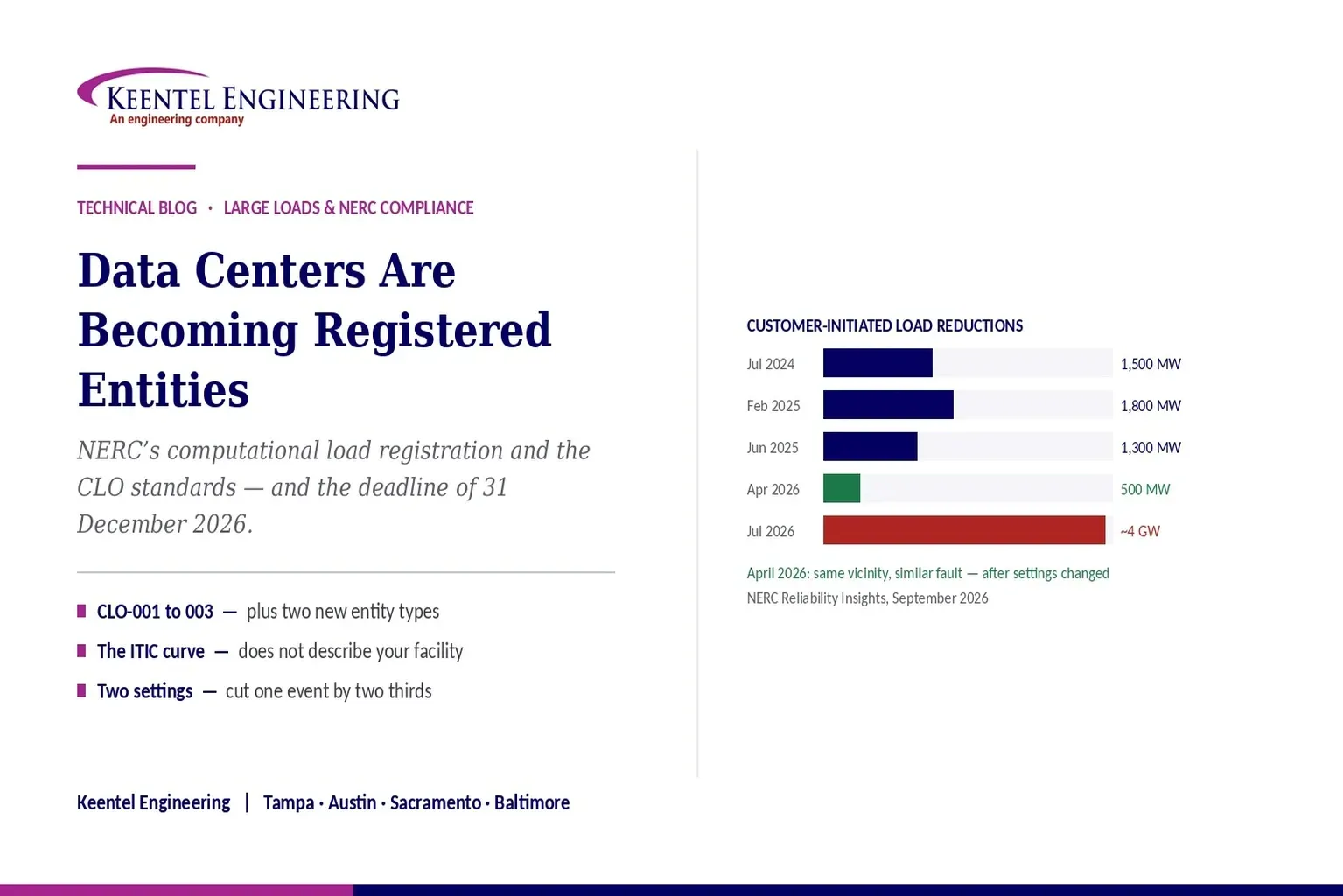
Learn how NERC computational load registration impacts data centers, CLO standards, ride-through requirements, modeling, and grid reliability compliance.
By SANDIP R PATEL
•
September 7, 2026
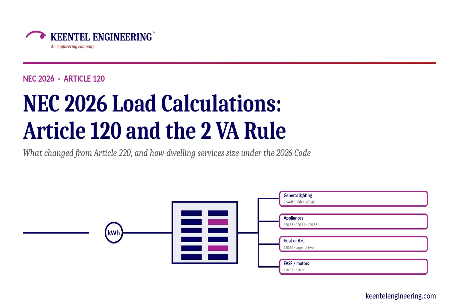
Learn NEC 2026 load calculations, Article 120 changes, the 2 VA rule, EV charging requirements, service sizing, and dwelling calculation methods.
By SANDIP R PATEL
•
September 7, 2026
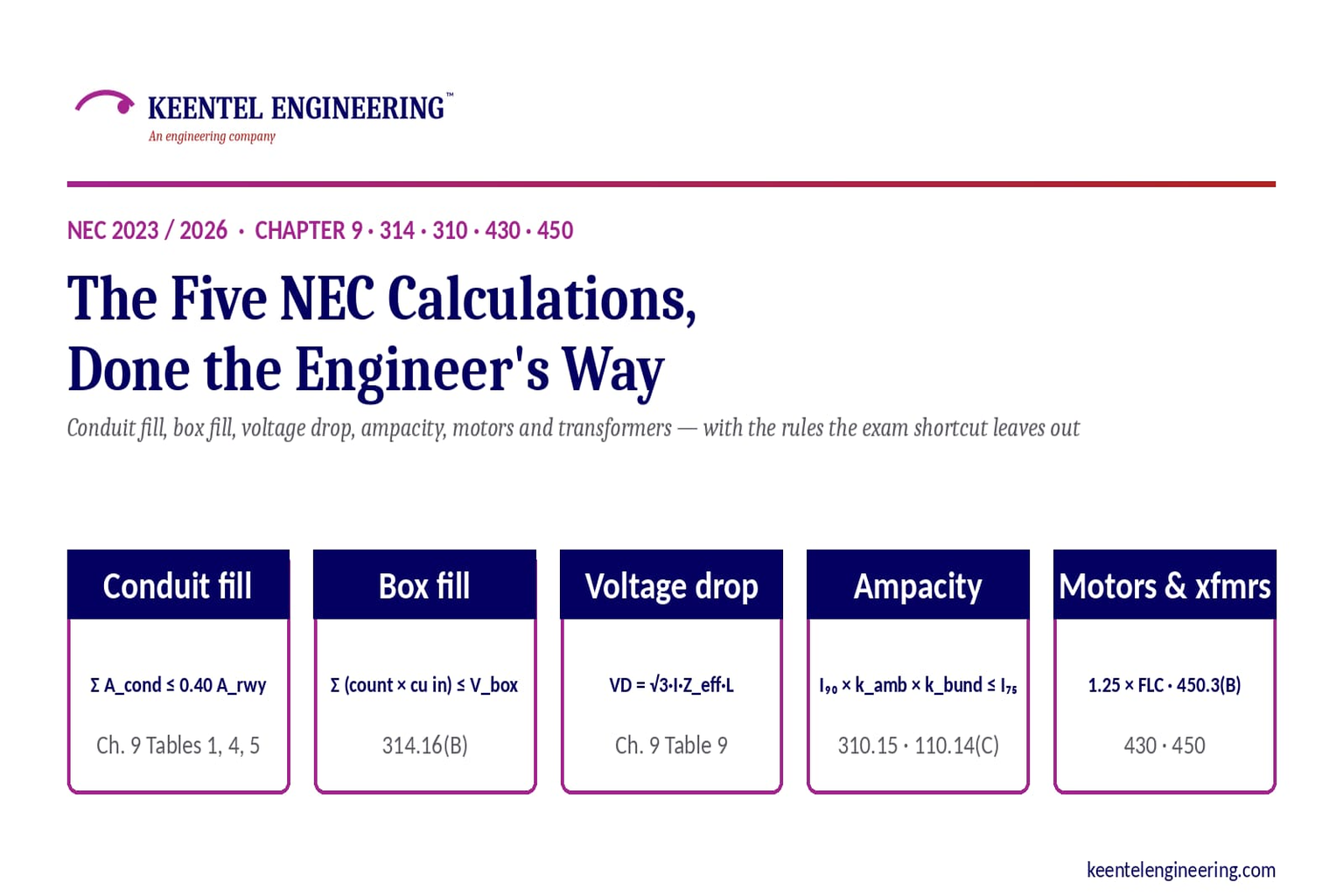
Learn five essential NEC calculations covering conduit fill, voltage drop, ampacity, motor circuits, and transformer protection with engineering examples.
By SANDIP R PATEL
•
September 7, 2026
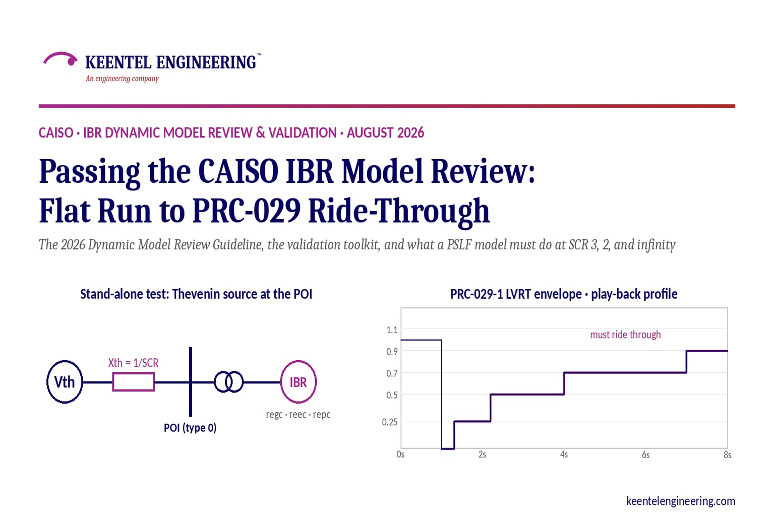
Learn how CAISO reviews IBR models using PSLF validation, PRC-029-1 ride-through requirements, WECC models, and inverter resource compliance testing.
By SANDIP R PATEL
•
September 7, 2026
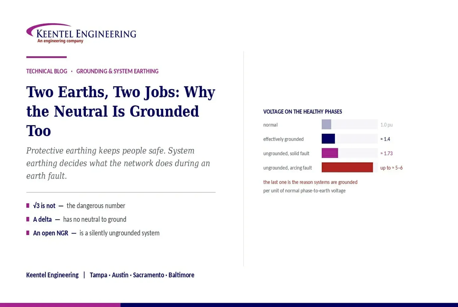
Understand system earthing and protective earthing, neutral grounding methods, effective grounding, ground grids, and insulation coordination for power systems
By SANDIP R PATEL
•
September 6, 2026
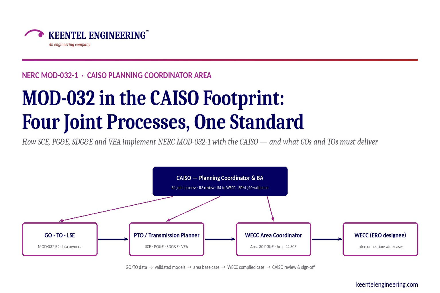
Learn how NERC MOD-032-1 applies across CAISO, SCE, PG&E, VEA and SDG&E, including generator data, PSLF models, EMT requirements and WECC submissions.
By SANDIP R PATEL
•
September 6, 2026
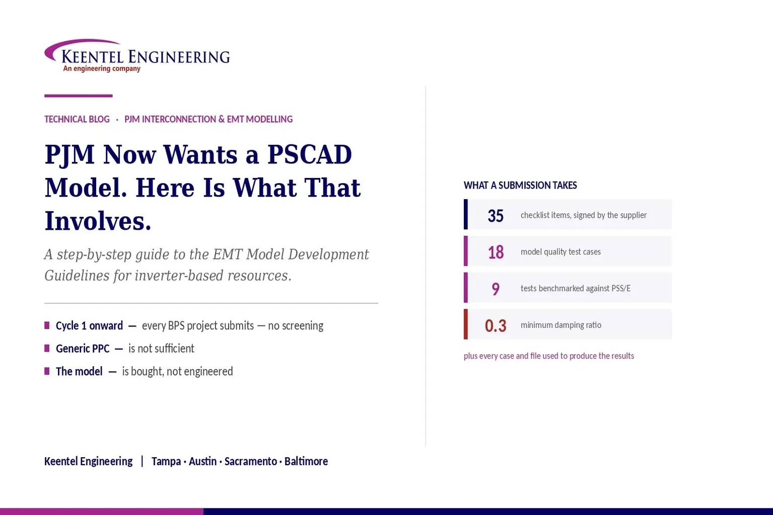
Learn PJM PSCAD model requirements for inverter-based resources, EMT testing, PSS/E benchmarking, ride-through studies, and compliance submissions
By SANDIP R PATEL
•
September 6, 2026
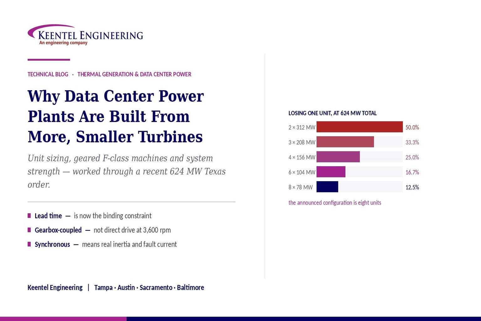
Learn why data center power plants use multiple smaller gas turbines, covering 624 MW capacity, redundancy, grid connection, system strength, and engineering.
By SANDIP R PATEL
•
September 5, 2026
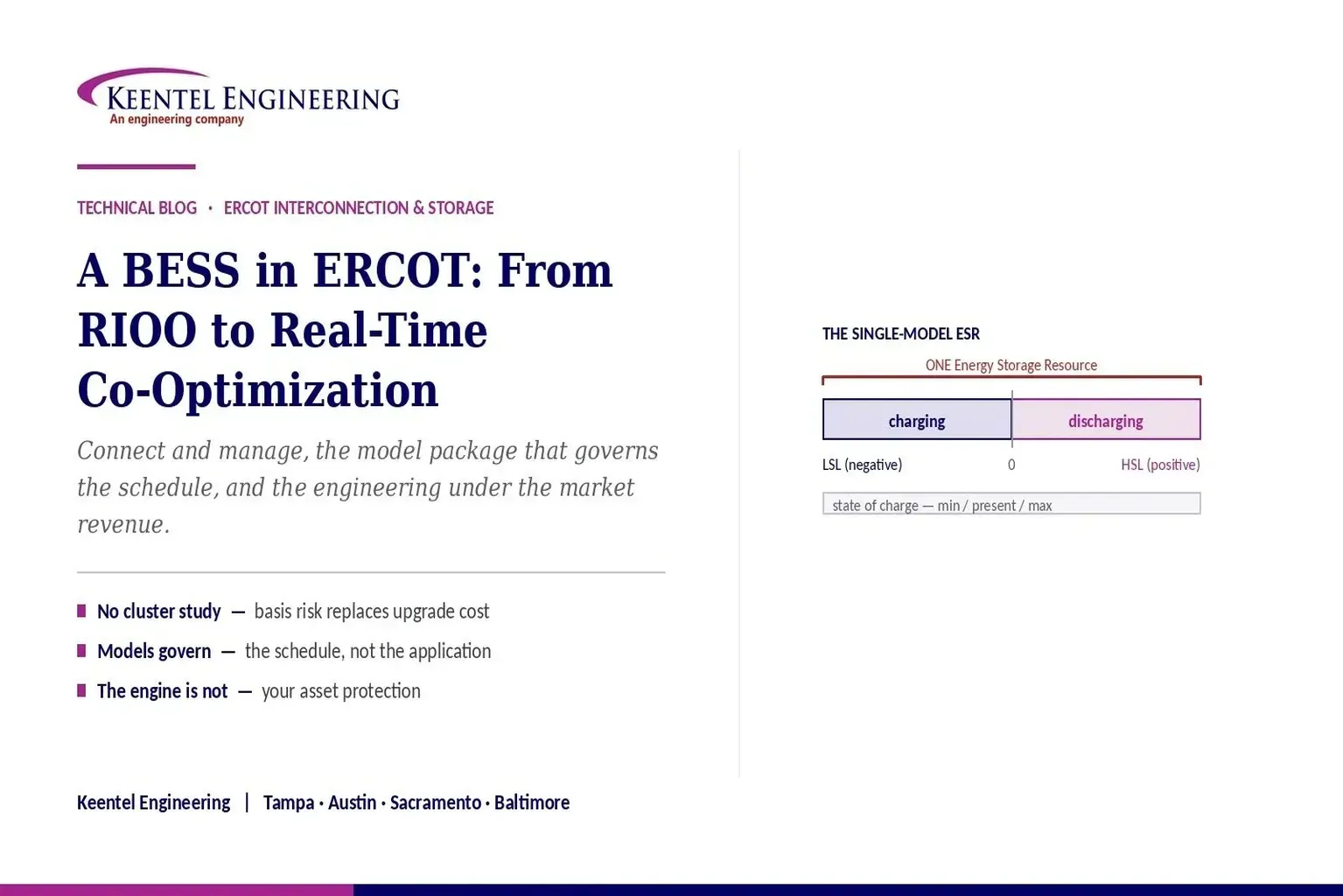
Understand ERCOT BESS interconnection requirements, including model packages, EMT studies, ride-through compliance, telemetry, and real-time co-optimization.





