
A Coordinated Electric System Interconnection Review—the utility’s deep-dive on technical and cost impacts of your project.
Challenge: Frequent false tripping using conventional electromechanical relays
Solution: SEL-487E integration with multi-terminal differential protection and dynamic inrush restraint
Result: 90% reduction in false trips, saving over $250,000 in downtime
ERCOT enforces all of the above through simulation, which means your model is your compliance case. The bar is now high:
- Whole-facility scope. The model must represent everything the IT load, the UPS and power conversion, the cooling plant, the protection and control systems in formats compatible with ERCOT's study platforms (PSS/E, PSCAD, TSAT).
- Real control loops, not approximations. Generic textbook representations are unacceptable. The model must capture the actual inner control behavior of your power electronics.
- Hardware-validated converter models. For electronic loads, the PSCAD model must be benchmarked against actual hardware testing including voltage ride-through and subsynchronous response. A model assembled from standard PSCAD library blocks fails by definition, because a generic block has never been tested against your vendor's hardware. The good news: validation is a hardware-type test, so results for a given converter product are reusable across every facility that uses it.
- Format migration. Facilities that previously submitted the older composite load model (CMLD) format must transition to EPRI's PERC1 format.
- Three checkpoints. Models are reviewed before the stability study begins (no model, no study), before each quarterly stability assessment, and for electronic loads one final time before energization, when you must submit as-built models with a documented comparison against the previously studied data and a sworn attestation that the model matches actual field settings. ERCOT's review takes 10 business days, extendable by 20 put it on your critical path.
- A living obligation. Change your technology, controls, or relay settings in a way that affects ride-through including converting a crypto mining site to an AI data center — and you've triggered a new interconnection study, even if your megawatts don't change.
| Parameter | Detail |
|---|---|
| System | 230 kV / 138 kV transmission corridors, wind and wet-snow icing exposure |
| Data basis | 15 years of minute-resolution forced-outage records + regional weather observations |
| Core methods | Event grouping, MVA performance curves, time-to-95%-restore, area outage rate curves, fragility modeling, rerun-history benefits, exceedance and log-domain risk metrics |
| Headline result | ≈85% of maximum resilience benefit at 60% of original capital; worst-event restoration window cut from 11 days to 5 in rerun-history terms |
| Decision supported | Capital portfolio selection; resilience plan filing; post-investment verification framework |
| System / Topic | Governing Standard(s) | What It Controls |
|---|---|---|
| Overall plant electrical distribution | IEEE 141 (Red Book); IEEE 666 | Distribution architecture, voltage selection, design of generating station auxiliary service systems |
| Power system studies | IEEE 399 (Brown Book); IEEE 551 | Load flow, symmetrical/asymmetrical short circuit, motor starting methodologies down to the lowest LV panelboard |
| Protection & coordination | IEEE 242 (Buff Book); IEEE 3004.5; IEEE C37 series | Generator relaying (21, 59N, 87G), time-current coordination, selective clearing between LV and MV tiers |
| GSU / UAT / SST transformers | IEEE C57.12.00 and C57 family | Transformer ratings, impedance, testing, loading |
| HV switchyard breakers | IEEE C37.06 | AC high-voltage circuit breaker preferred ratings |
| MV switchgear (13.8 kV) | IEEE C37.20.2; IEEE C37.20.7 | Metal-clad construction, compartmentalization, vacuum breakers; arc-resistant design with plenum venting |
| MV cable | UL 1072; ICEA S-93-639 (NEMA WC 74) | Type MV-105 shielded cable, 133% insulation level for HRG systems |
| LV switchgear (480 V) | IEEE C37.13; UL 1558 | Metal-enclosed LV power circuit breaker switchgear to 635 V, draw-out ACBs with electronic trip units |
| Motor control centers | UL 845; NEMA ICS 18 | LV-MCC construction, MCCB/MCP protection for motors under ~200 HP |
| Motors | NEMA MG-1 | Motor performance, starting characteristics, service factors |
| DC & battery systems | IEEE 485; IEEE 946 | Lead-acid battery sizing (125/250 VDC), DC auxiliary system design |
| Grounding | IEEE 80; IEEE 142 (Green Book) | Ground grid step/touch potential limits; system grounding including high-resistance grounding |
| Lightning protection | IEEE 998 | Direct-stroke shielding of switchyard and outdoor generator structures |
| Arc flash & electrical safety | IEEE 1584; NFPA 70E | Incident energy calculation; worker safety boundaries and PPE |
| Fire protection | NFPA 850 | Fire protection and risk management for combustion turbine generating plants |
| Installation code | NEC (NFPA 70); NESC | Wiring methods inside the plant fence; overhead/outdoor clearances at the switchyard |
| Interconnection & compliance | FERC LGIP; NERC MOD-025/026/027, PRC-019/024/029, FAC-008 | Interconnection process, model validation, protection/ride-through coordination, facility ratings |
| IFC / Construction Deliverable | Purpose |
|---|---|
| Stamped IFC packages | Legal basis for construction; P.E. responsible charge |
| Final relay settings & TCCs | Protection as-installed matches the coordination study |
| Calculation archive | Owner records; NERC audit evidence trail |
| Commissioning procedures | Safe, sequenced energization; MOD field testing |
| Construction support | RFIs, field changes, FAT/SAT witness |
| As-builts & model handoff | Operating baseline; future study currency |
| Metric | Outcome |
|---|---|
| Defects found pre-occupancy | Three topology defects and one settings-mismatch family corrected before load migration; the shared-switchboard defect alone would have invalidated the concurrently-maintainable claim on day one |
| IST findings | Fourteen additional discrepancies surfaced under scenario testing (control logic, alarm mapping, one generator sequencing fault) — all closed before handover instead of during operations |
| Black-building test | Passed on second execution; the first attempt exposed the generator sequencing fault under true block load, exactly the failure the compressed plan would never have found |
| Handover quality | Operations team certified on the actual failure scenarios; corrected EOPs and settings documentation delivered as controlled documents |
| Business outcome | Occupancy proceeded three weeks behind the original date — against an independent estimate that the uncorrected sequencing fault carried a high probability of a full facility outage within the first year |
Part 2 — Frequently Asked Questions: Large Load Interconnection
| Contact | Details |
|---|---|
| Headquarters | 400 N Ashley Dr STE 2600, Tampa, FL 33602 |
| Phone | (813) 389-7871 |
| contact@keentelengineering.com | |
| Florida Firm Registration | No. 36853 |
| Additional Offices | Austin, TX • Sacramento, CA • Baltimore, MD |
| Who | Acronym | Plain-English Role |
|---|---|---|
| ERCOT | — | The grid's air traffic controller. It doesn't own power lines or plants; it directs the flow of electricity across most of Texas and referees the admission process for new generators. |
| Interconnecting Entity | IE | You — the developer or owner trying to connect a new plant (or significantly modify an existing one). You file the application and drive the process. |
| Resource Entity | RE | The registered owner/operator of the generator once it becomes an official market participant. Often the same company as the IE, wearing a different hat. |
| Qualified Scheduling Entity | QSE | Your plant's voice on the grid. The QSE handles round-the-clock communications with ERCOT — telemetry, schedules, dispatch instructions. Every generator must have one. |
| Transmission Service Provider | TSP | The utility that owns the wires and substation you'll connect to. The TSP runs your detailed study, builds the connection facilities, and signs your interconnection contract. |
| RIOO-IS | — | ERCOT's online portal where the whole process lives — applications, documents, status tracking, and checklists all flow through it. |
| Who | Acronym | Plain-English Role |
|---|---|---|
| ERCOT | — | The grid's air traffic controller. It doesn't own power lines or plants; it directs the flow of electricity across most of Texas and referees the admission process for new generators. |
| Interconnecting Entity | IE | You — the developer or owner trying to connect a new plant (or significantly modify an existing one). You file the application and drive the process. |
| Resource Entity | RE | The registered owner/operator of the generator once it becomes an official market participant. Often the same company as the IE, wearing a different hat. |
| Qualified Scheduling Entity | QSE | Your plant's voice on the grid. The QSE handles round-the-clock communications with ERCOT — telemetry, schedules, dispatch instructions. Every generator must have one. |
| Transmission Service Provider | TSP | The utility that owns the wires and substation you'll connect to. The TSP runs your detailed study, builds the connection facilities, and signs your interconnection contract. |
| RIOO-IS | — | ERCOT's online portal where the whole process lives — applications, documents, status tracking, and checklists all flow through it. |
| Who | Acronym | Plain-English Role |
|---|---|---|
| ERCOT | — | The grid's air traffic controller. It doesn't own power lines or plants; it directs the flow of electricity across most of Texas and referees the admission process for new generators. |
| Interconnecting Entity | IE | You — the developer or owner trying to connect a new plant (or significantly modify an existing one). You file the application and drive the process. |
| Resource Entity | RE | The registered owner/operator of the generator once it becomes an official market participant. Often the same company as the IE, wearing a different hat. |
| Qualified Scheduling Entity | QSE | Your plant's voice on the grid. The QSE handles round-the-clock communications with ERCOT — telemetry, schedules, dispatch instructions. Every generator must have one. |
| Transmission Service Provider | TSP | The utility that owns the wires and substation you'll connect to. The TSP runs your detailed study, builds the connection facilities, and signs your interconnection contract. |
| RIOO-IS | — | ERCOT's online portal where the whole process lives — applications, documents, status tracking, and checklists all flow through it. |
| Who | Acronym | Plain-English Role |
|---|---|---|
| ERCOT | — | The grid's air traffic controller. It doesn't own power lines or plants; it directs the flow of electricity across most of Texas and referees the admission process for new generators. |
| Interconnecting Entity | IE | You — the developer or owner trying to connect a new plant (or significantly modify an existing one). You file the application and drive the process. |
| Resource Entity | RE | The registered owner/operator of the generator once it becomes an official market participant. Often the same company as the IE, wearing a different hat. |
| Qualified Scheduling Entity | QSE | Your plant's voice on the grid. The QSE handles round-the-clock communications with ERCOT — telemetry, schedules, dispatch instructions. Every generator must have one. |
| Transmission Service Provider | TSP | The utility that owns the wires and substation you'll connect to. The TSP runs your detailed study, builds the connection facilities, and signs your interconnection contract. |
| RIOO-IS | — | ERCOT's online portal where the whole process lives — applications, documents, status tracking, and checklists all flow through it. |
| Who | Acronym | Plain-English Role |
|---|---|---|
| ERCOT | — | The grid's air traffic controller. It doesn't own power lines or plants; it directs the flow of electricity across most of Texas and referees the admission process for new generators. |
| Interconnecting Entity | IE | You — the developer or owner trying to connect a new plant (or significantly modify an existing one). You file the application and drive the process. |
| Resource Entity | RE | The registered owner/operator of the generator once it becomes an official market participant. Often the same company as the IE, wearing a different hat. |
| Qualified Scheduling Entity | QSE | Your plant's voice on the grid. The QSE handles round-the-clock communications with ERCOT — telemetry, schedules, dispatch instructions. Every generator must have one. |
| Transmission Service Provider | TSP | The utility that owns the wires and substation you'll connect to. The TSP runs your detailed study, builds the connection facilities, and signs your interconnection contract. |
| RIOO-IS | — | ERCOT's online portal where the whole process lives — applications, documents, status tracking, and checklists all flow through it. |
| Who | Acronym | Plain-English Role |
|---|---|---|
| ERCOT | — | The grid's air traffic controller. It doesn't own power lines or plants; it directs the flow of electricity across most of Texas and referees the admission process for new generators. |
| Interconnecting Entity | IE | You — the developer or owner trying to connect a new plant (or significantly modify an existing one). You file the application and drive the process. |
| Resource Entity | RE | The registered owner/operator of the generator once it becomes an official market participant. Often the same company as the IE, wearing a different hat. |
| Qualified Scheduling Entity | QSE | Your plant's voice on the grid. The QSE handles round-the-clock communications with ERCOT — telemetry, schedules, dispatch instructions. Every generator must have one. |
| Transmission Service Provider | TSP | The utility that owns the wires and substation you'll connect to. The TSP runs your detailed study, builds the connection facilities, and signs your interconnection contract. |
| RIOO-IS | — | ERCOT's online portal where the whole process lives — applications, documents, status tracking, and checklists all flow through it. |
| Who | Acronym | Plain-English Role |
|---|---|---|
| ERCOT | — | The grid's air traffic controller. It doesn't own power lines or plants; it directs the flow of electricity across most of Texas and referees the admission process for new generators. |
| Interconnecting Entity | IE | You — the developer or owner trying to connect a new plant (or significantly modify an existing one). You file the application and drive the process. |
| Resource Entity | RE | The registered owner/operator of the generator once it becomes an official market participant. Often the same company as the IE, wearing a different hat. |
| Qualified Scheduling Entity | QSE | Your plant's voice on the grid. The QSE handles round-the-clock communications with ERCOT — telemetry, schedules, dispatch instructions. Every generator must have one. |
| Transmission Service Provider | TSP | The utility that owns the wires and substation you'll connect to. The TSP runs your detailed study, builds the connection facilities, and signs your interconnection contract. |
| RIOO-IS | — | ERCOT's online portal where the whole process lives — applications, documents, status tracking, and checklists all flow through it. |
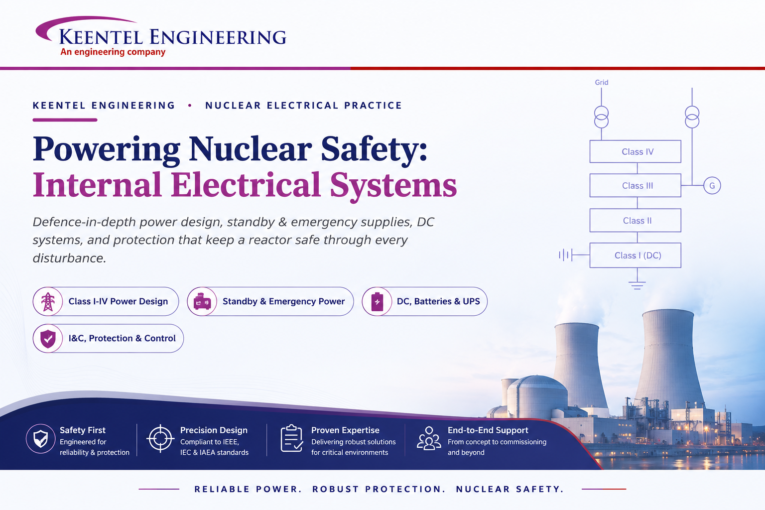
Powering Nuclear Safety: Internal Electrical Systems in Nuclear Power Plants
Jul 25, 2026 | Blog
How defence-in-depth power design, standby and emergency supplies, DC systems, and protection keep a reactor safe through every disturbanc
In a nuclear power plant, electricity does far more than turn a generator and feed the grid. It runs the pumps that cool the reactor, the instruments that watch it, the logic that trips it, and the systems that remove decay heat long after the reactor is shut down. Almost every system in the station depends on electrical power to operate — which is why the design of a plant’s internal electrical systems is one of the most important safety considerations in building and operating a nuclear station.
The governing principle is simple to state and demanding to engineer: power must come from diverse and reliable sources that are physically and electrically isolated, so that any single failure affects only one supply and cannot propagate to the others. Electrical systems are designed not only for normal operation, but for every credible condition other than normal — transients, faults, loss of the grid, and post-shutdown decay-heat removal.
At Keentel Engineering, our nuclear electrical practice is built around that principle. This article explains how a modern station (using the CANDU design as a worked example) structures its power sources, why the four-class power scheme exists, and how Keentel supports nuclear utilities across the full electrical scope — Class I–IV power system design, standby and emergency power, DC systems and batteries, and instrumentation, protection, and load control.
Diverse, Independent, Defence-in-Depth Power
Because nearly all plant systems rely on electricity, the strategy for electrical supplies is defence-in-depth: rely on multiple, diverse, and independent sources so that no single event can remove them all. A CANDU unit draws on six sources of power:
- Power generated from the unit itself
- Power generated from other units within the same station
- Off-site power obtained from the grid
- The emergency power supply
- The standby power supply
- Batteries
These supply both AC and DC power, and they are arranged in escalating layers of defence:
- 1st line — Normal operation (grid plus the main generator).
- 2nd line — Mitigation (standby generators plus batteries).
- 3rd line — Station blackout (batteries plus a designated alternative source).
- 4th line — Severe accident management (additional, diverse, alternative sources).
Equipment is also graded by its importance to safety. If electrical generation is lost, the limited alternative sources are directed first and foremost to keep the essential safety-related systems running. Getting that grading right — which load sits on which supply, and why — is the heart of nuclear electrical design.
Voltage levels across the station
A CANDU plant contains several buses at different voltage levels, selected to meet plant- and country-specific requirements. In one representative design, the generator produces at 22 kV; the unit service transformer (UST) and station service transformer (SST) step to secondary voltages such as 11.6 kV and 4.16 kV; and the site has two independent off-site grid connections — for example, one at 500 kV and one at 220 kV. That diversity of incoming supply is itself a safety feature: two physically separate grid connections plus internally generated power.
The Four-Class Power Scheme
The defining idea in nuclear electrical design is that power sources are classified by how long an interruption the loads they feed can tolerate. This yields four classes. The most critical safety-related control and protection systems are fed from Class I and Class II; capacity and cost per kW increase from Class I toward Class IV, while the allowable interruption time increases in the same direction.
Table 1 — Classification of power sources
| Class | Type | Allowed interruption | Typical role |
|---|---|---|---|
| Class I | DC | Never (uninterruptible) | Most critical safety/control loads; battery-backed |
| Class II | AC | ~4 milliseconds | Reactor regulation, digital control computers, I&C |
| Class III | AC | Up to ~5 minutes | Large process/heat-sink loads; standby-generator backed |
| Class IV | AC | Indefinite | Balance-of-plant; not required for safe shutdown |
For extra reliability, Class II, III, and IV power are each distributed through two separate divisions — often called Bus A and Bus B, or the Odd Bus and Even Bus — with loads split evenly between them. A failure on one division leaves the equipment on the other still available. The two divisions can be tied through normally-open circuit breakers that must be deliberately commanded to close, preserving independence in normal operation.
Channelization and two-out-of-three voting
Independence extends into instrumentation. Important functions use three instrument channels to provide immunity against single instrument faults, with a two-out-of-three voting strategy — two of the three channels must be outside acceptable limits before the system trips or actuates. This lets any one channel be tested or fail without spuriously tripping the plant or masking a real demand, and it is mirrored in the three independent channels of Class II inverters that feed the triplicated I&C.
The Keentel Nuclear Electrical Practice: Four Connected Services
Keentel supports nuclear utilities across the full internal-electrical scope. The four service areas below map directly onto the architecture above — and, as in any safety-graded system, their value comes from being engineered together.
1. Class I–IV Power System Design
Keentel designs and analyzes the four-class power architecture end to end: matching each load to the correct class by its safety function and tolerable interruption, sizing the safety-related buses, laying out the two-division (odd/even) split for redundancy, and engineering the interconnections and grading that make defence-in-depth real rather than nominal. This includes the UST/SST arrangement, the class interconnections (rectifiers feeding Class I, inverters feeding Class II, standby generators feeding Class III), and the load-flow, short-circuit and coordination studies that underpin them.
2. Standby and Emergency Power (SG / EPS)
A nuclear station carries two distinct families of on-site backup, and Keentel engineers both. Standby generators (SGs) — two or more diesel- or combustion-turbine-driven sets — start automatically on loss of Class IV power, feed Class III at 6.3 kV, and carry their own compressed-air and DC start systems; they are fuelled to run for extended periods (up to a week). Emergency power systems (EPS) are the second, seismically-qualified family: fully independent of the other sources, they start on loss of Class IV or on a loss-of-coolant-accident (LOCA) signal to enable reactor shutdown, monitoring, and decay-heat removal. Keentel’s scope covers sizing, sequencing, LOCA response (SGs up within ~30 seconds and loads picked up within a further three minutes; EPS running with its intended loads within three minutes), and the periodic-test regime that keeps these sets trustworthy.
3. DC Systems, Batteries and UPS
The uninterruptible backbone of the plant is DC. Class I is a DC source with three independent distribution channels, each battery-backed, with rectifiers converting Class III AC to DC to both feed the bus and keep the batteries fully charged, and inverters (DC/AC) converting Class I DC to Class II AC. On loss of Class III, the batteries provide a seamless, no-break transfer — but only for a finite window, typically about 60 minutes, which makes restoration of Class III within that interval a critical design constraint. Keentel engineers the battery banks, chargers, rectifiers, inverters and DC/AC converters, the multiple DC voltage levels (e.g. 48 V, 220/250 V, 400 V), and safeguards such as keeping the 48 V and 250 V DC systems ungrounded with ground-fault detection so a single line-to-ground fault does not cause a service interruption.
4. I&C, Protection and Load Control
Finally, Keentel engineers the systems that sense, decide, and switch. This spans the triplicated instrumentation and two-out-of-three protection logic; the control of electrical loads through relay/logic and interposing circuits (typically powered from 48 V DC Class I); switchgear control circuits fed from the 250 V DC Class I batteries; motor-control-centre (MCC) circuits fed from 120 V AC; and the ON/AUTO/STANDBY load-operation modes selected from the main or secondary control room. It also includes grounding and lightning protection — required to prevent injury and equipment damage, limit electromagnetic effects, and keep safety-related monitoring alive when lightning strikes facilities or lines.
Keeping the Lights On: Load Transfer and Continuity
Reliability is not only about having backup sources — it is about moving between them without upsetting the plant. At the upper voltage level of Class IV, loads are shifted between the unit service transformer and the station service transformer to prevent a reactor trip and keep generation online. Three transfer modes are used:
- Parallel transfer — parallel the new source to the existing one, then remove the old source to complete the change.
- Fast transfer — switch the load within about two power cycles, so almost no interruption is seen.
- Slow transfer — used after voltage decays to ~40% to limit re-energization voltage and inrush, where the transformers and re-acceleration allow it.
Class IV transfers are initiated manually for normal start-up and shutdown, and automatically on reactor trips, turbine-generator trips, or loss of the transmission system. Automatic transfer also protects Class II: schemes monitor the inverters and, under defined conditions, transfer Class II buses directly to Class III within each channel. Engineering these transfer schemes — and proving they behave correctly under fault — is a core part of nuclear electrical work.
Why the 60-minute battery window matters
If Class III power cannot be restored while the batteries carry Class I and II, all uninterruptible power is eventually lost. Every element above — fast standby-generator starting, seismically-qualified EPS, load-transfer schemes, and disciplined battery maintenance — exists to make sure that window is never exhausted. Keentel designs and tests to that margin, not just to the nominal case.
Why Nuclear Operators Partner with Keentel
Nuclear electrical systems are unforgiving of gaps between disciplines. The value Keentel brings is engineering the whole safety-graded chain as one system — the four power classes, the standby and emergency sources, the DC backbone, and the protection and control that tie them together — so that independence, redundancy, and defence-in-depth hold up not just on the single-line diagram but under real faults.
- Safety-graded by design — every load matched to the right power class by its safety function and tolerable interruption.
- Independence preserved — physically and electrically separated sources, two-division buses, and triplicated, two-out-of-three I&C.
- Backup you can trust — standby and seismically-qualified emergency power engineered and tested for LOCA and station-blackout response.
- No-break DC backbone — batteries, chargers, rectifiers and inverters sized to the real restoration window, with ungrounded-system safeguards.
- Continuity under transfer — parallel, fast, and slow transfer schemes proven to avoid spurious trips.
A nuclear plant’s electrical systems are its nervous system and its last line of defence at the same time. Keentel Engineering helps nuclear utilities design, upgrade, and maintain those systems so the reactor stays safe, monitored, and cooled through every disturbance — from a routine bus transfer to a station blackout.
To discuss a Class I–IV design or review, a standby/emergency power upgrade, a DC-system and battery study, or protection and load-control engineering, talk to the Keentel Engineering nuclear electrical practice.
Frequently Asked Questions
Common questions from nuclear utility and plant-operator teams about internal electrical systems and Keentel’s services.
Why are internal electrical systems so critical to nuclear safety?
Almost every system in a nuclear plant relies on electrical power — the pumps that cool the reactor, the instruments that monitor it, the logic that trips it, and the systems that remove decay heat after shutdown. Because of that dependence, electrical supplies are engineered not only for normal operation but for every credible off-normal condition. Power must come from diverse and reliable sources that are physically and electrically isolated, so any single failure affects only one supply and cannot propagate to the others.
What is defence-in-depth for electrical power?
It is the strategy of relying on multiple, diverse, and independent power sources arranged in escalating layers. In a CANDU station the layers are: 1st line — normal operation (grid plus main generator); 2nd line — mitigation (standby generators plus batteries); 3rd line — station blackout (batteries plus a designated alternative source); and 4th line — severe accident management (additional diverse sources). Equipment is graded by its importance to safety, so if generation is lost, the limited alternative sources are directed first to the essential safety-related systems.
What are the six sources of power in a CANDU unit?
Power generated from the unit itself; power generated from other units within the same station; off-site power from the grid; the emergency power supply; the standby power supply; and batteries. Together these provide both AC and DC power, and they are deliberately kept independent so a single event cannot remove them all.
What do the four classes of power mean?
Power sources are classified by how long an interruption their loads can tolerate. Class I cannot be interrupted at all (it is DC, battery-backed). Class II can tolerate about a 4-millisecond interruption (AC, via inverters). Class III can tolerate up to about 5 minutes (AC, backed by standby generators). Class IV can tolerate interruption indefinitely (balance-of-plant loads). The most critical safety-related control and protection systems run on Class I and Class II.
Why is Class I a DC system with batteries?
Class I feeds loads that can never be interrupted, so it uses DC backed by battery banks across three independent channels. During normal operation, rectifiers convert Class III AC to DC to feed the loads while keeping the batteries fully charged; inverters convert that DC to AC for Class II. If Class III power is lost, the batteries provide a seamless, no-break transfer. Importantly, the batteries can carry the DC buses for only a finite time — typically about 60 minutes — which is why restoring Class III power within that window is a critical design requirement.
What is the difference between standby generators and emergency power systems?
Both are on-site backup that start automatically on loss of Class IV power, but they differ in qualification and independence. Standby generators (SGs) are diesel- or combustion-turbine-driven, feed Class III at 6.3 kV, carry their own air and DC start systems, and are fuelled for extended operation; they are not required to be seismically qualified. Emergency power systems (EPS) are seismically qualified and function completely independently of the other sources, providing power for reactor shutdown, monitoring, and decay-heat removal — including on a loss-of-coolant-accident (LOCA) signal.
How fast must backup power respond to a LOCA?
On a loss-of-coolant-accident signal, standby generators should be up and running within about 30 seconds and pick up all designated loads within a further three minutes. Emergency power systems are expected to be running with their intended loads within three minutes. A single standby generator is sized with enough capacity to supply the required loads.
What is channelization and two-out-of-three voting?
Important safety functions use three independent instrument channels so that a single instrument fault cannot disable the function or cause a spurious trip. With a two-out-of-three voting strategy, two of the three channels must be outside acceptable limits before the system trips or actuates. This lets any one channel be tested or fail safely, and it is supported by three independent channels of Class II inverters feeding the triplicated instrumentation and control.
How is power transferred between sources without tripping the plant?
At the upper voltage level of Class IV, loads are shifted between the unit service transformer and the station service transformer using three modes: parallel transfer (parallel the new source, then drop the old), fast transfer (switch within about two power cycles for near-zero interruption), and slow transfer (after voltage decays to about 40%, to limit inrush). These are initiated manually for normal start-up and shutdown, and automatically for reactor trips, turbine-generator trips, or loss of the transmission system.
What nuclear electrical services does Keentel Engineering provide?
Keentel supports nuclear utilities across four connected areas: Class I–IV power system design (architecture, load grading, two-division buses, and the supporting studies); standby and emergency power (SG and seismically-qualified EPS design, sequencing, LOCA response, and testing); DC systems, batteries and UPS (battery banks, chargers, rectifiers, inverters, multiple DC voltage levels, and ungrounded-system safeguards); and I&C, protection and load control (triplicated instrumentation and two-out-of-three logic, switchgear and MCC control, and grounding and lightning protection). Delivering all four together keeps independence and defence-in-depth intact across the whole system.
How do we start working with Keentel on a nuclear project?
Most engagements begin with a focused scope — a Class I–IV design or independent review, a standby/emergency power upgrade, a DC-system and battery capacity study, or a protection and load-control assessment — and can broaden across the full electrical lifecycle from new build through refurbishment and life-extension. Reach out to the Keentel Engineering nuclear electrical practice to discuss your station and objectives.

About the Author:
Sandip "Sonny" R. Patel, P.E.
IEEE Senior Member · Founder & CEO, Keentel Engineering
In 1995, Sonny Patel earned his Electrical Engineering degree from the University of Illinois. But degrees don't build legacies — action does.
For three decades, he has worked the power industry from every side of the table: 16 years as a utility engineer at Exelon/Commonwealth Edison; generation leadership across hydroelectric, industrial steam turbine, and a 9 GW renewable fleet; NERC Regional Entity Senior Compliance Engineer and Audit Team Lead, auditing some of the nation's largest utilities; and testing and commissioning lead on equipment up to 765 kV — the very top of the North American grid.Utility. Generator. Regulator. Consultant. Few engineers have seen all four seats. Fewer still have sat in them.
His experience spans nuclear, hydro, conventional generation, renewables, oil and gas, mining — and today's data centers, where he is authoring a three-book series on data center design. He is a Licensed Professional Engineer in six states and a Licensed Electrical Contractor in Florida (Unlimited EC) — he doesn't just design the work; he's qualified to stand behind its execution.Today, as Founder and CEO of Keentel Engineering, Sonny leads a nationwide team of engineers delivering substation design, power system studies, NERC compliance, and commissioning — done right, coast to coast.Three decades. Every side of the table. One standard: accountable engineering.
Services

Let's Discuss Your Project
Let's book a call to discuss your electrical engineering project that we can help you with.
About the Author:
Sandip "Sonny" R. Patel, P.E.
IEEE Senior Member · Founder & CEO, Keentel Engineering
In 1995, Sonny Patel earned his Electrical Engineering degree from the University of Illinois. But degrees don't build legacies — action does.
For three decades, he has worked the power industry from every side of the table: 16 years as a utility engineer at Exelon/Commonwealth Edison; generation leadership across hydroelectric, industrial steam turbine, and a 9 GW renewable fleet; NERC Regional Entity Senior Compliance Engineer and Audit Team Lead, auditing some of the nation's largest utilities; and testing and commissioning lead on equipment up to 765 kV — the very top of the North American grid.
Utility. Generator. Regulator. Consultant. Few engineers have seen all four seats. Fewer still have sat in them.
His experience spans nuclear, hydro, conventional generation, renewables, oil and gas, mining — and today's data centers, where he is authoring a three-book series on data center design. He is a Licensed Professional Engineer in six states and a Licensed Electrical Contractor in Florida (Unlimited EC) — he doesn't just design the work; he's qualified to stand behind its execution.
Today, as Founder and CEO of Keentel Engineering, Sonny leads a nationwide team of engineers delivering substation design, power system studies, NERC compliance, and commissioning — done right, coast to coast.Three decades. Every side of the table. One standard: accountable engineering.
Leave a Comment
Thank you for contacting us.
We will get back to you as soon as possible.
We will get back to you as soon as possible.
Oops, there was an error sending your message.
Please try again later.
Please try again later.
Related Posts
By SANDIP R PATEL
•
October 23, 2026
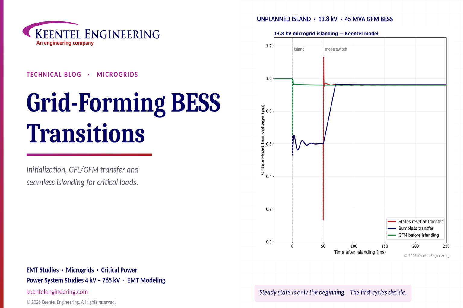
Explore grid-forming BESS initialization, GFL-to-GFM transitions, seamless islanding, EMT simulations, current limiting and microgrid protection.
By SANDIP R PATEL
•
October 23, 2026
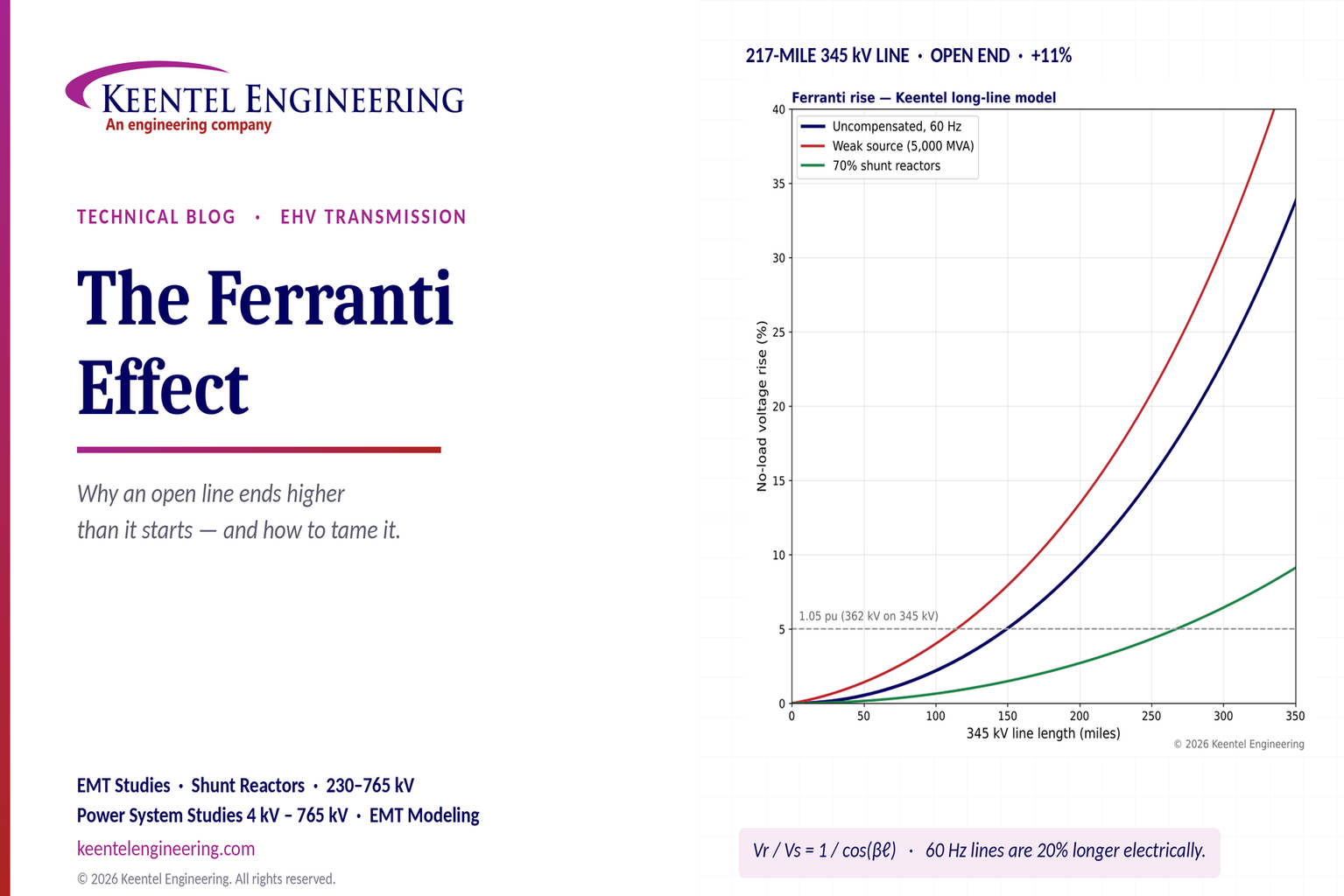
Explore the Ferranti effect in EHV transmission lines: voltage rise, 345 kV examples, switching overvoltages, shunt reactor sizing and mitigation.
By SANDIP R PATEL
•
October 23, 2026
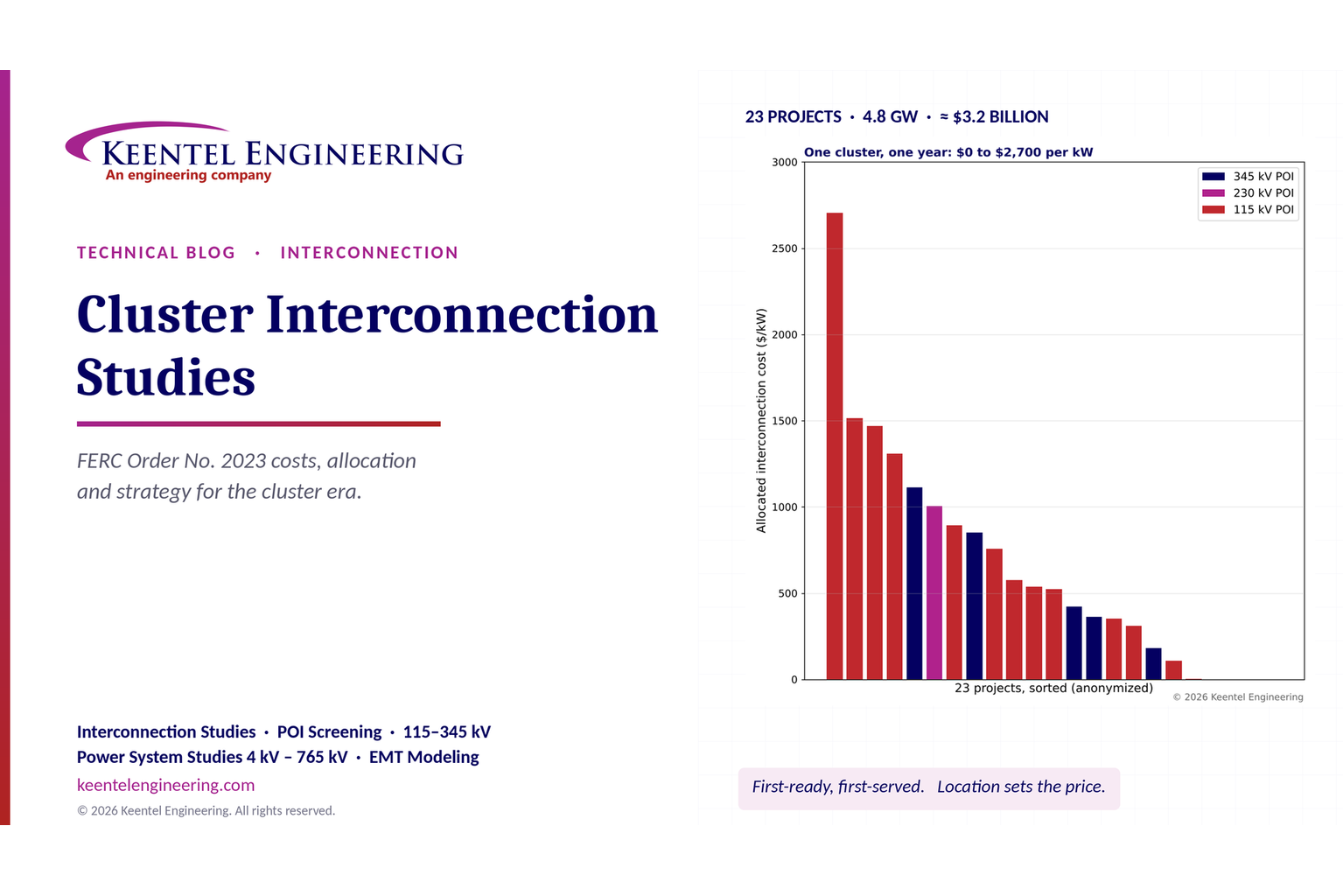
Explore cluster interconnection studies under FERC Order 2023, including network upgrades, cost allocation, withdrawal penalties and developer strategy.
By SANDIP R PATEL
•
October 21, 2026
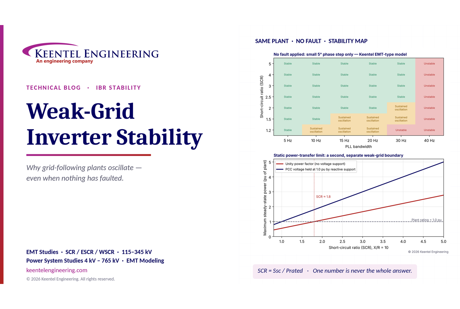
Learn why grid-following inverters become unstable without grid faults. Explore SCR, PLL interactions, EMT studies, grid strength, and mitigation.
By SANDIP R PATEL
•
October 21, 2026
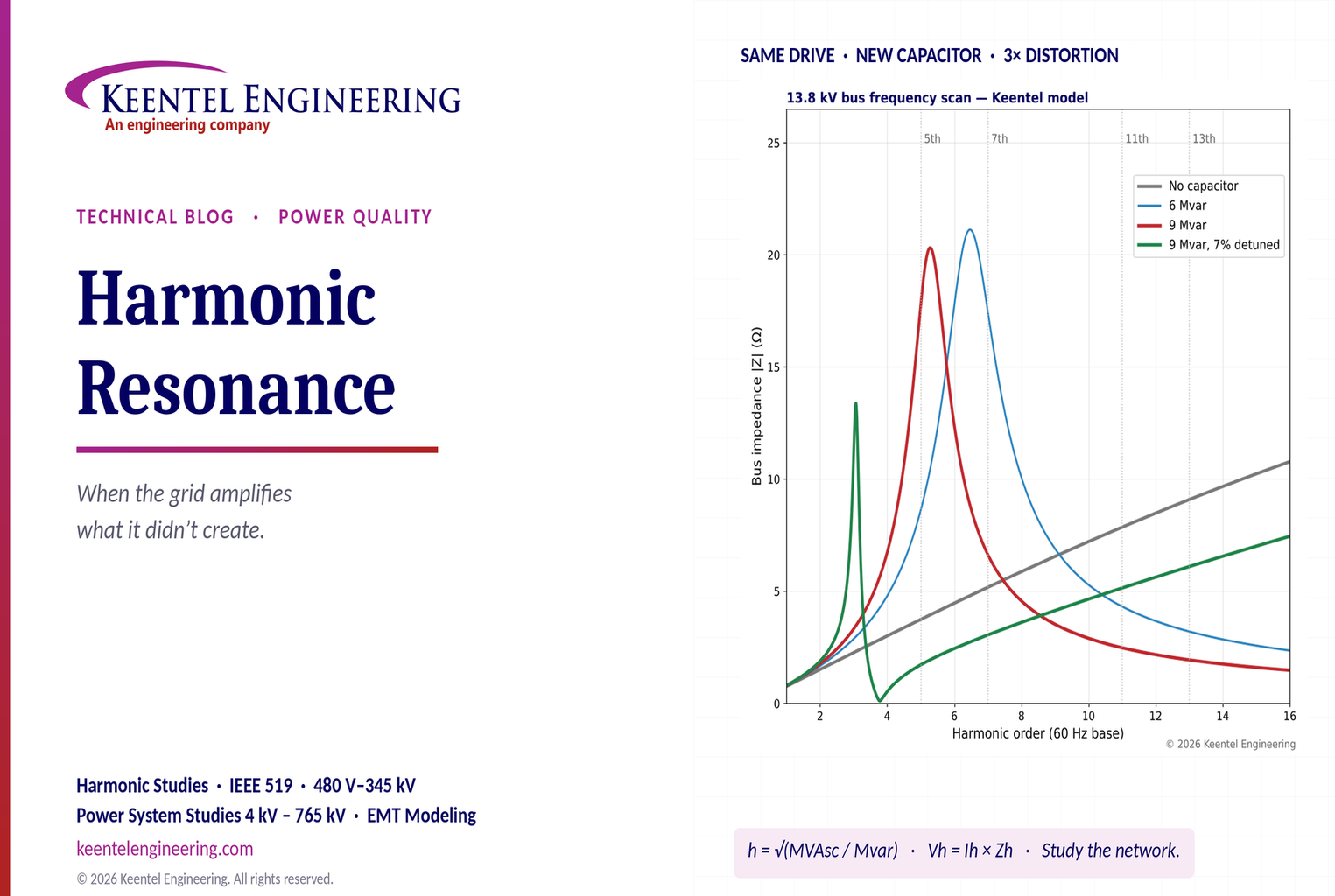
Learn how harmonic resonance amplifies distortion in power systems. Explore capacitor banks, detuned reactors, frequency scans, and IEEE 519 solutions.
By SANDIP R PATEL
•
October 20, 2026
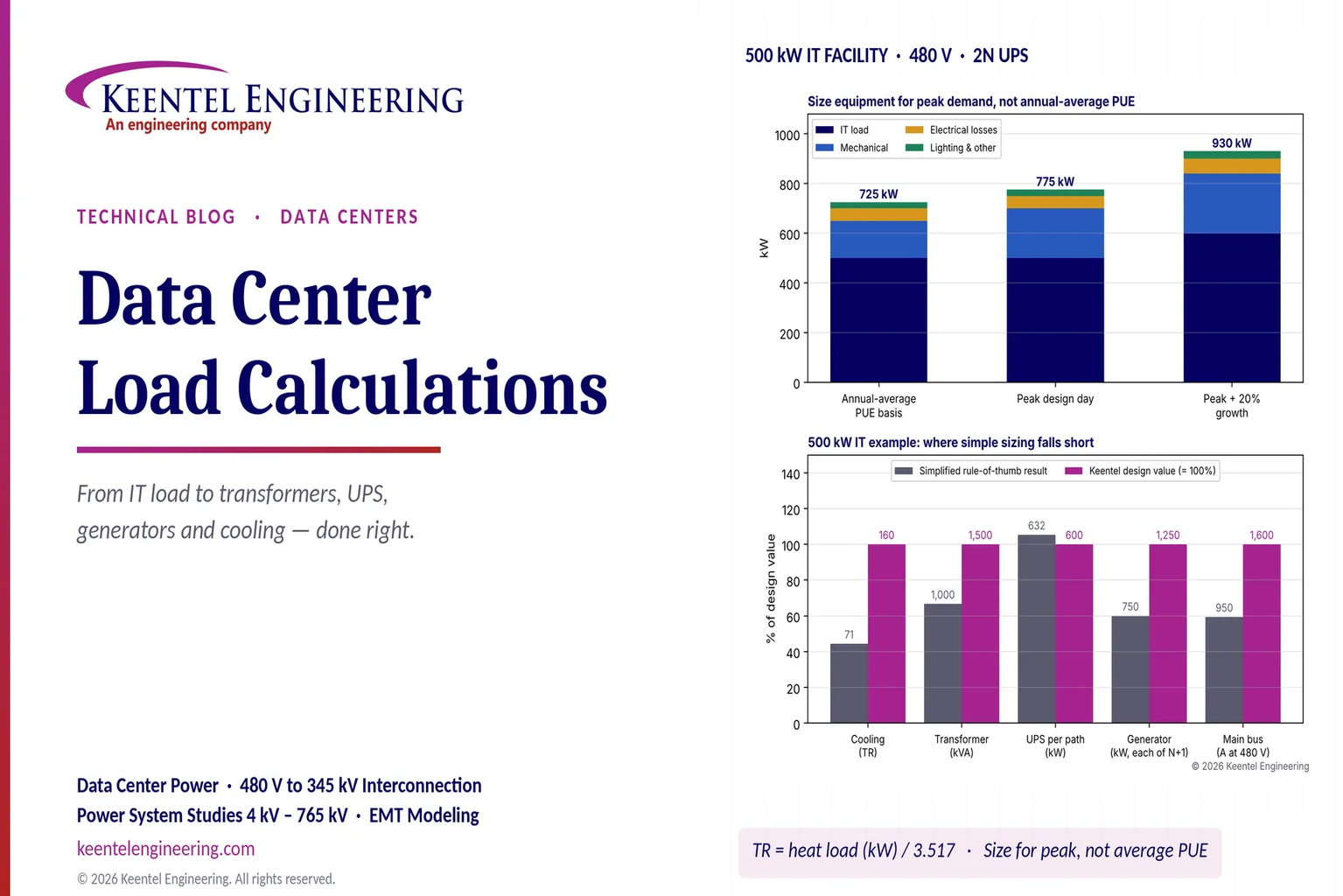
Learn data center electrical load calculations, including IT demand, PUE, UPS and generator sizing, cooling loads, redundancy, and worked US examples.
By SANDIP R PATEL
•
October 20, 2026
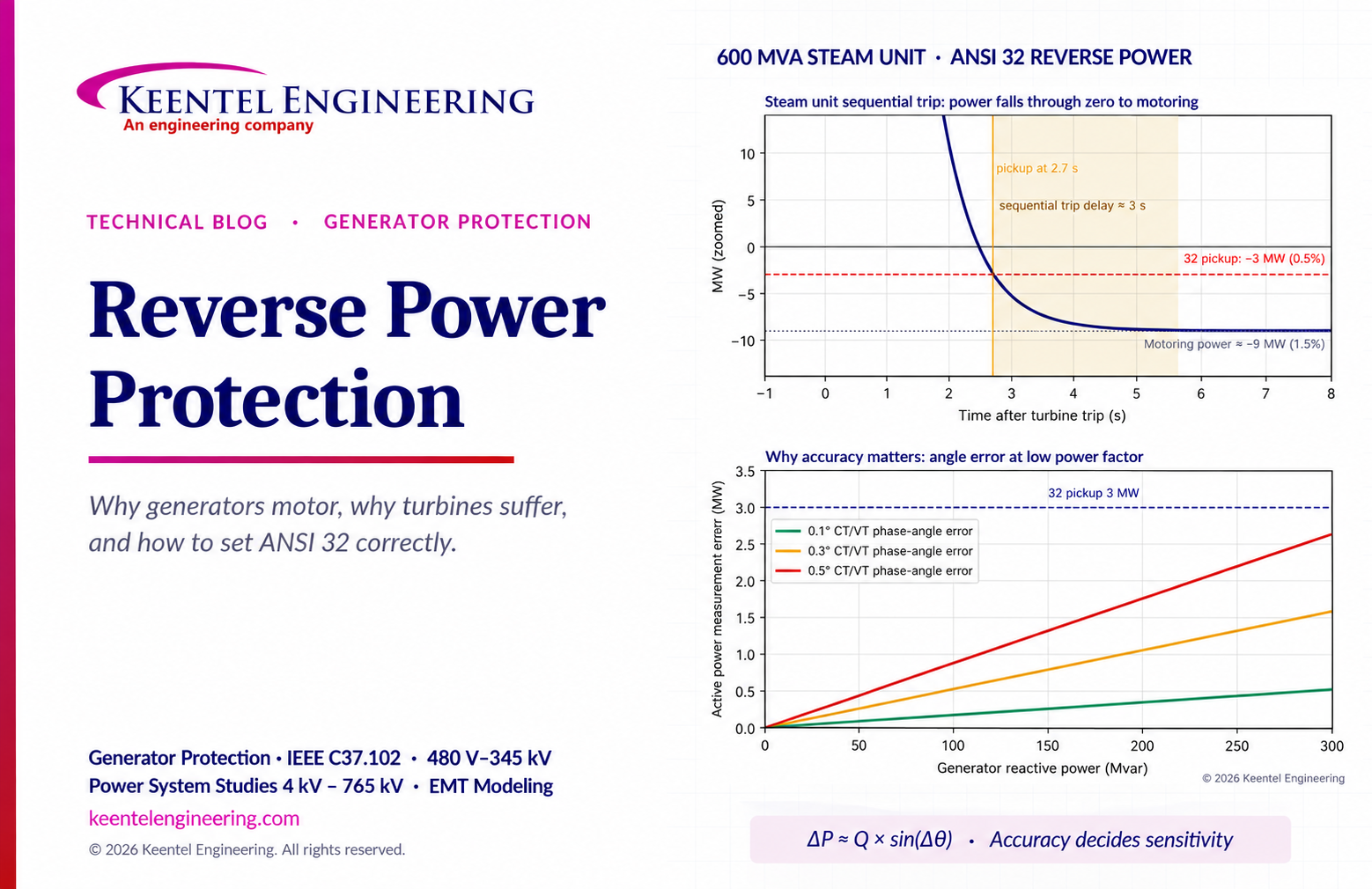
Learn reverse power protection (ANSI 32), generator motoring, relay pickup settings, time delays, sequential tripping and testing for US power plants.

By Team 2 Dexora
•
October 20, 2026
Explore grounding system testing with Keentel Engineering. Learn IEEE 80/81 methods, soil resistivity, ground resistance, and touch and step voltage safety.

By SANDIP R PATEL
•
October 13, 2026
Plan data center capacity with land screening, MW-per-acre estimates, grid power availability and interconnection feasibility studies from Keentel Engineering.





