
A Coordinated Electric System Interconnection Review—the utility’s deep-dive on technical and cost impacts of your project.
Challenge: Frequent false tripping using conventional electromechanical relays
Solution: SEL-487E integration with multi-terminal differential protection and dynamic inrush restraint
Result: 90% reduction in false trips, saving over $250,000 in downtime
ERCOT enforces all of the above through simulation, which means your model is your compliance case. The bar is now high:
- Whole-facility scope. The model must represent everything the IT load, the UPS and power conversion, the cooling plant, the protection and control systems in formats compatible with ERCOT's study platforms (PSS/E, PSCAD, TSAT).
- Real control loops, not approximations. Generic textbook representations are unacceptable. The model must capture the actual inner control behavior of your power electronics.
- Hardware-validated converter models. For electronic loads, the PSCAD model must be benchmarked against actual hardware testing including voltage ride-through and subsynchronous response. A model assembled from standard PSCAD library blocks fails by definition, because a generic block has never been tested against your vendor's hardware. The good news: validation is a hardware-type test, so results for a given converter product are reusable across every facility that uses it.
- Format migration. Facilities that previously submitted the older composite load model (CMLD) format must transition to EPRI's PERC1 format.
- Three checkpoints. Models are reviewed before the stability study begins (no model, no study), before each quarterly stability assessment, and for electronic loads one final time before energization, when you must submit as-built models with a documented comparison against the previously studied data and a sworn attestation that the model matches actual field settings. ERCOT's review takes 10 business days, extendable by 20 put it on your critical path.
- A living obligation. Change your technology, controls, or relay settings in a way that affects ride-through including converting a crypto mining site to an AI data center — and you've triggered a new interconnection study, even if your megawatts don't change.
| Parameter | Detail |
|---|---|
| System | 230 kV / 138 kV transmission corridors, wind and wet-snow icing exposure |
| Data basis | 15 years of minute-resolution forced-outage records + regional weather observations |
| Core methods | Event grouping, MVA performance curves, time-to-95%-restore, area outage rate curves, fragility modeling, rerun-history benefits, exceedance and log-domain risk metrics |
| Headline result | ≈85% of maximum resilience benefit at 60% of original capital; worst-event restoration window cut from 11 days to 5 in rerun-history terms |
| Decision supported | Capital portfolio selection; resilience plan filing; post-investment verification framework |
| System / Topic | Governing Standard(s) | What It Controls |
|---|---|---|
| Overall plant electrical distribution | IEEE 141 (Red Book); IEEE 666 | Distribution architecture, voltage selection, design of generating station auxiliary service systems |
| Power system studies | IEEE 399 (Brown Book); IEEE 551 | Load flow, symmetrical/asymmetrical short circuit, motor starting methodologies down to the lowest LV panelboard |
| Protection & coordination | IEEE 242 (Buff Book); IEEE 3004.5; IEEE C37 series | Generator relaying (21, 59N, 87G), time-current coordination, selective clearing between LV and MV tiers |
| GSU / UAT / SST transformers | IEEE C57.12.00 and C57 family | Transformer ratings, impedance, testing, loading |
| HV switchyard breakers | IEEE C37.06 | AC high-voltage circuit breaker preferred ratings |
| MV switchgear (13.8 kV) | IEEE C37.20.2; IEEE C37.20.7 | Metal-clad construction, compartmentalization, vacuum breakers; arc-resistant design with plenum venting |
| MV cable | UL 1072; ICEA S-93-639 (NEMA WC 74) | Type MV-105 shielded cable, 133% insulation level for HRG systems |
| LV switchgear (480 V) | IEEE C37.13; UL 1558 | Metal-enclosed LV power circuit breaker switchgear to 635 V, draw-out ACBs with electronic trip units |
| Motor control centers | UL 845; NEMA ICS 18 | LV-MCC construction, MCCB/MCP protection for motors under ~200 HP |
| Motors | NEMA MG-1 | Motor performance, starting characteristics, service factors |
| DC & battery systems | IEEE 485; IEEE 946 | Lead-acid battery sizing (125/250 VDC), DC auxiliary system design |
| Grounding | IEEE 80; IEEE 142 (Green Book) | Ground grid step/touch potential limits; system grounding including high-resistance grounding |
| Lightning protection | IEEE 998 | Direct-stroke shielding of switchyard and outdoor generator structures |
| Arc flash & electrical safety | IEEE 1584; NFPA 70E | Incident energy calculation; worker safety boundaries and PPE |
| Fire protection | NFPA 850 | Fire protection and risk management for combustion turbine generating plants |
| Installation code | NEC (NFPA 70); NESC | Wiring methods inside the plant fence; overhead/outdoor clearances at the switchyard |
| Interconnection & compliance | FERC LGIP; NERC MOD-025/026/027, PRC-019/024/029, FAC-008 | Interconnection process, model validation, protection/ride-through coordination, facility ratings |
| IFC / Construction Deliverable | Purpose |
|---|---|
| Stamped IFC packages | Legal basis for construction; P.E. responsible charge |
| Final relay settings & TCCs | Protection as-installed matches the coordination study |
| Calculation archive | Owner records; NERC audit evidence trail |
| Commissioning procedures | Safe, sequenced energization; MOD field testing |
| Construction support | RFIs, field changes, FAT/SAT witness |
| As-builts & model handoff | Operating baseline; future study currency |
| Metric | Outcome |
|---|---|
| Defects found pre-occupancy | Three topology defects and one settings-mismatch family corrected before load migration; the shared-switchboard defect alone would have invalidated the concurrently-maintainable claim on day one |
| IST findings | Fourteen additional discrepancies surfaced under scenario testing (control logic, alarm mapping, one generator sequencing fault) — all closed before handover instead of during operations |
| Black-building test | Passed on second execution; the first attempt exposed the generator sequencing fault under true block load, exactly the failure the compressed plan would never have found |
| Handover quality | Operations team certified on the actual failure scenarios; corrected EOPs and settings documentation delivered as controlled documents |
| Business outcome | Occupancy proceeded three weeks behind the original date — against an independent estimate that the uncorrected sequencing fault carried a high probability of a full facility outage within the first year |
Part 2 — Frequently Asked Questions: Large Load Interconnection
An electric grid must remain in continuous balance — generation onto the grid must equal consumption from it at every instant. PJM achieves this balance, and prices it, through a layered market architecture. Each layer operates on a different time horizon, and each one touches project economics differently.
| Domain | Key Standards / Codes | What They Govern |
|---|---|---|
| Fire safety | NFPA 855; UL 9540 / UL 9540A | Installation requirements, separation, gas management; system safety listing and thermal-runaway fire testing |
| Grid interconnection | IEEE 1547 (distribution); IEEE 2800 (transmission IBRs) | Ride-through, reactive capability, power quality, and performance at the point of interconnection |
| Power quality | IEEE 519 | Harmonic distortion limits at the PCC |
| Protection & grounding | IEEE 80 / 81 / 142; C37 series | Grounding system design and testing; protective relaying |
| Reliability compliance | NERC standards (incl. PRC ride-through requirements) | Registered-entity obligations for grid-connected storage |
Re-Engineering a Pole-Mounted Distribution Transformer to IEEE, ANSI, and NESC
Aug 20, 2026 | Blog
1. Start with the system
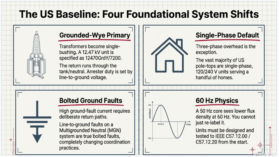
- Transformers become single-bushing (grounded-wye primary). A 12.47 kV pole-mount unit is typically specified as 12470GrdY/7200 — one primary bushing at 7,200 V line-to-neutral with the return through the tank/neutral. The Indian design’s three fully-insulated primary bushings become one bushing per single-phase unit.
- Arrester duty is set by line-to-ground voltage, not line-to-line. This is what lets a US 12.47 kV system use a 10 kV duty-cycle arrester where an ungrounded 12 kV system would need substantially more.
- Single-phase service is the default, not the exception. A large fraction of US pole-top transformers are single-phase, 120/240 V, serving a handful of houses. The three-phase pole-top unit shown in the rendering is the unusual case in US practice, not the base case.
- Ground-fault current is high and the return path is deliberate. Line-to-ground faults on an MGN system are true bolted faults, sized comparably to three-phase faults, which is why US fusing and coordination practice looks nothing like IEC-region practice.
And frequency matters more than people expect. A 50 Hz core operated at 60 Hz sees lower flux density and different loss and excitation behavior; impedance and regulation shift too. You cannot re-label a 50 Hz transformer as a 60 Hz unit — it has to be designed and tested to IEEE C57.12.00 and C57.12.20 from the start.
2. Voltage class: what "12 kV" actually means
Per
ANSI/NEMA C84.1-2020 (R2025), the standard nominal distribution system voltages are:
| Nominal system voltage | Line-to-neutral | Class | Standard BIL (dist. xfmr) |
|---|---|---|---|
| 4160Y/2400 | 2,400 V | 5 kV | 60 kV |
| 12470Y/7200 | 7,200 V | 15 kV | 95 kV (110 kV alt.) |
| 13200Y/7620 | 7,620 V | 15 kV | 95 kV (110 kV alt.) |
| 13800Y/7970 | 7,970 V | 15 kV | 95 kV (110 kV alt.) |
| 24940Y/14400 | 14,400 V | 25 kV | 125 kV (150 kV alt.) |
| 34500Y/19920 | 19,920 V | 35 kV | 150 kV (200 kV alt.) |
Two notes worth internalizing.
First, 12.47 kV, 13.2 kV, and 13.8 kV all share the 15 kV insulation class. Insulation, arresters, cutouts, and cable are ordered by class, not by nominal voltage. This is why "15 kV class" is the phrase that appears on most US distribution material specs.
Second, C84.1 Range A above 600 V is +5% / −2.5%, not the symmetric ±5% that applies at 600 V and below. On a 12,470 V nominal system, Range A service voltage is 12,157–13,094 V. Designers who carry the ±5% low-voltage habit upward into MV voltage-drop studies will size regulation wrong on the low side.
3. Component-by-component translation
| Rendering (IS/CBIP) | US equivalent | Governing standard |
|---|---|---|
| LA (lightning arrester) | MOV surge arrester, distribution class | IEEE C62.11-2020 |
| Hot line clamp | Hotline clamp / compression connector | ANSI C119.4-2022 |
| Disc insulator | Porcelain pin, polymer line post, or polymer deadend | ANSI C29.2 / C29.5 / C29.6 / C29.7 / C29.13 / C29.18 |
| Cross arm V-bracket | 8–10 ft wood or fiberglass crossarm with braces | NESC Sec. 26, Rule 261; RUS 1724E-150 |
| D.O. fuse cutout | Fused cutout with expulsion fuse link | IEEE/ANSI C37.42 |
| Guy assembly | Down guy, anchor, guy strain insulator, guy guard | NESC Rule 261, Table 261-1 |
| 25 kVA, 11/0.4 kV 3-ph | 1-ph units banked, or 3-ph pole-mount ≤500 kVA | IEEE C57.12.20-2023 |
| LT cable | Triplex/quadruplex secondary and service drop | NESC Sec. 23; ICEA/NEMA |
| LT MCCB box | Generally not present — see §6 | — |
| PCC pole, 8 m, base plate | Direct-embedded wood pole, 40–50 ft, Class 1–5 | ANSI O5.1-2022 |
| Earthing | Pole ground bonded to the multigrounded neutral | NESC Sec. 9, Rules 093–096 |
Insulators
The rendering shows disc (suspension) insulators on the primary. In US distribution tangent construction, the phase conductor typically sits on a pin insulator (ANSI C29.5 for low/medium voltage, C29.6 for high-voltage pin) or, increasingly, a polymer line post (C29.18 for distribution line post — note that C29.17 is the transmission line post and is a common miscitation). Suspension/deadend discs per C29.2 appear at deadends, corners, and dead-end riser poles, not at a typical tangent transformer pole.
Poles
This is the most visually obvious change. The US default is a direct-embedded wood pole to ANSI O5.1-2022, not a spun prestressed concrete pole on a base plate. Setting depth follows the standard 10%-plus-2-feet rule of thumb, checked against NESC Section 26 / Rule 261 strength requirements for Grade B or Grade C construction and the applicable Heavy/Medium/Light loading district under NESC Section 25. RUS Bulletin 1724E-150 — the federal design guide for rural distribution — is written almost entirely around unguyed wood poles, Classes 1–6, 35–55 ft.
Spun concrete poles do exist in the US and are covered by ASTM C1089-19 (R2025). They are a deliberate, cost-justified exception (coastal corrosion, fire-hardening, decay zones), not the baseline. And be careful with citations: the ANSI C136 series is roadway and area lighting equipment, not utility distribution concrete poles.
Connectors
The hotline clamp translates directly, but the qualification basis changes. ANSI C119.4-2022 governs aluminum-to-aluminum and aluminum-to-copper connectors on distribution and transmission lines. Its Class A / Class B designations are electrical current-cycle test classes — Class A is 500 current cycles, Class B is 250 — plus separate mechanical strength classes 1, 2, and 3. They are not connector "types," and specifying "Class A" without also specifying the mechanical class leaves the spec incomplete.
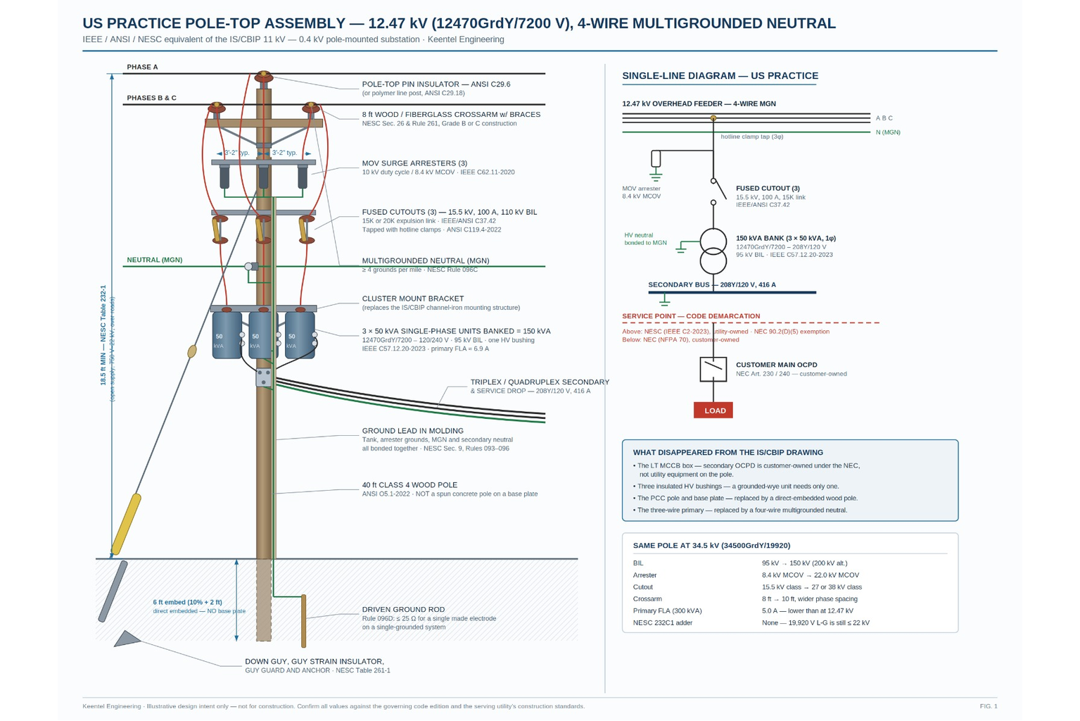
Figure 1, on the following page, shows the whole assembly rebuilt — elevation and single-line — alongside a summary of what the 34.5 kV version changes.
FIGURE 1 — US-practice pole-top assembly at 12.47 kV (12470GrdY/7200 V), 4-wire multigrounded neutral
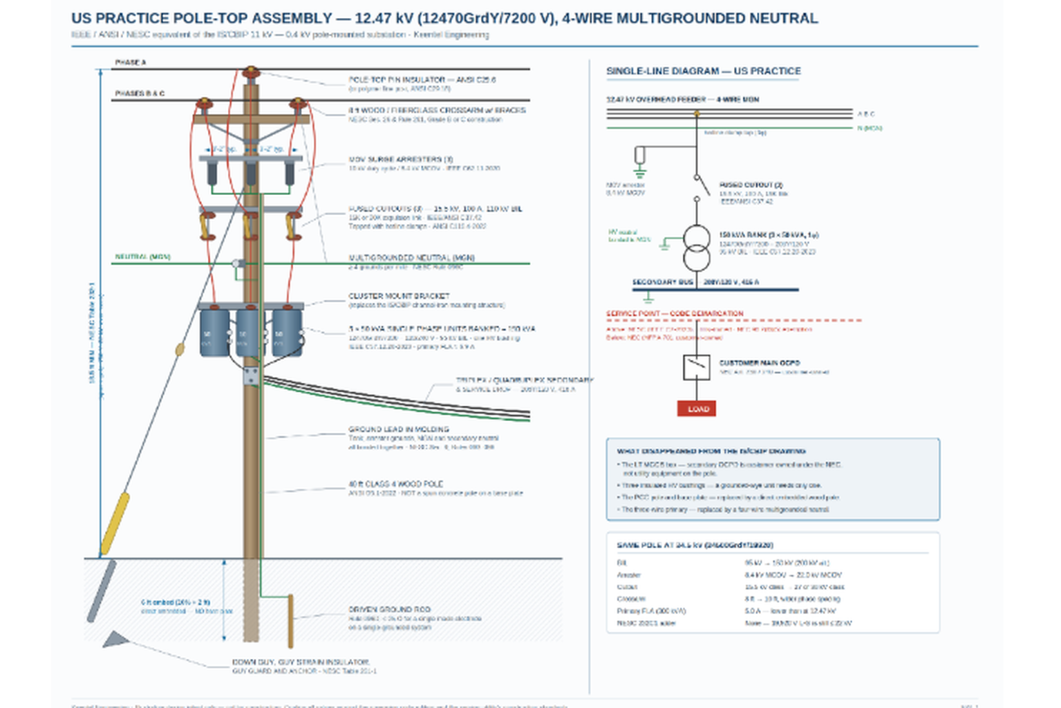
The IEEE / ANSI / NESC equivalent of the IS/CBIP 12 kV — 0.4 kV pole-mounted substation. Illustrative design intent only — not for construction.
4. Worked example A — 12.47 kV suburban commercial tap
Design intent: three-phase, 208Y/120 V service to a small commercial building off a 12.47 kV MGN feeder.
| Parameter | Value | Basis |
|---|---|---|
| System | 12470GrdY/7200 V, 4-wire MGN | ANSI C84.1-2020 |
| Transformer | 150 kVA, 3 × 50 kVA 1-ph banked, 7200 – 120/240 | IEEE C57.12.20-2023 |
| Secondary connection | 208Y/120 V | — |
| Primary BIL | 95 kV | IEEE C57.12.00 |
| Primary FLA | 150 kVA ÷ (√3 × 12.47 kV) ≈ 6.9 A | — |
| Fuse link | 15K or 20K, per utility table | IEEE/ANSI C37.42 |
| Cutout | 15.5 kV, 100 A cont., 110 kV BIL | IEEE/ANSI C37.42 |
| Arrester | 10 kV duty cycle / 8.4 kV MCOV (9 kV / 7.65 kV MCOV also valid) | IEEE C62.11-2020 |
| Secondary FLA | 150 kVA ÷ (√3 × 208 V) ≈ 416 A | — |
| Pole | 40 ft Class 4 wood, ~6 ft embedment | ANSI O5.1-2022 |
| Mounting | Cluster mount (1-ph units) or single-pole bracket | Utility standard |
Three single-phase units banked is deliberate. It is the common US route to three-phase overhead service: stock is standardized, a single failed unit is a cheap replacement, and the bank tolerates open-delta operation if one unit is lost. Three-phase pole-mounted units exist — triplex designs generally 30–225 kVA, T-connected up to 500 kVA — but they are a purchased exception at most utilities, not the default.
5. Worked example B — 34.5 kV rural / collector tap
Design intent: three-phase, 480Y/277 V auxiliary service off a 34.5 kV line — a very common arrangement for site power at a solar, wind, or BESS facility, and for rural three-phase irrigation and pumping loads.
| Parameter | Value | Basis |
|---|---|---|
| System | 34500GrdY/19920 V, 4-wire MGN | ANSI C84.1-2020 |
| Transformer | 300 kVA, 3-ph pole-mount or banked 1-ph, 19920 – 480Y/277 | IEEE C57.12.20-2023 |
| Primary BIL | 150 kV standard (200 kV alternative) | IEEE C57.12.00 |
| Primary FLA | 300 kVA ÷ (√3 × 34.5 kV) ≈ 5.0 A | — |
| Fuse link | 10K–15K, per utility table | IEEE/ANSI C37.42 |
| Cutout | 27 kV or 38 kV class, 100 A cont. | IEEE/ANSI C37.42 |
| Arrester | 27 kV duty cycle / 22.0 kV MCOV (30 kV / 24.4 kV MCOV also valid) | IEEE C62.11-2020 |
| Secondary FLA | 300 kVA ÷ (√3 × 480 V) ≈ 361 A | — |
| Pole | 45–50 ft Class 2–3 wood; 10 ft crossarm | ANSI O5.1-2022 |
Note what changes and what does not. Primary current falls — 5.0 A at 34.5 kV versus 6.9 A at 12.47 kV for a comparable load — which is exactly why 34.5 kV distribution wins on long rural feeders. What rises sharply is everything driven by dielectric stress: BIL goes 95 → 150 kV, phase spacing widens, crossarms lengthen, and the arrester’s MCOV nearly triples.
One clearance subtlety worth flagging. NESC Rule 232 / Table 232-1 brackets open supply conductors at "over 750 V to 22 kV," and for effectively grounded systems that threshold is applied phase-to-ground. A 34.5Y/19.92 kV system sits at 19,920 V line-to-ground — still inside the 22 kV bracket. So the base vertical clearances apply, and the Rule 232C1 adder of 0.4 in (10 mm) per kV above 22 kV does not kick in. Engineers who apply the adder off the 34.5 kV line-to-line number will over-build every crossing on the line. (Verify against the codebook for your specific configuration; ungrounded and delta systems are treated differently.)
6. Where the rendering has no US equivalent: the LT MCCB box
This is the most instructive difference on the whole pole.
The rendering shows an LT MCCB box below the transformer, and the accompanying SLD runs: overhead feeder → DO fuse cutout → transformer → LT box bus → MCCB → load. That secondary molded-case breaker is standard practice in IS/CBIP distribution substation design.
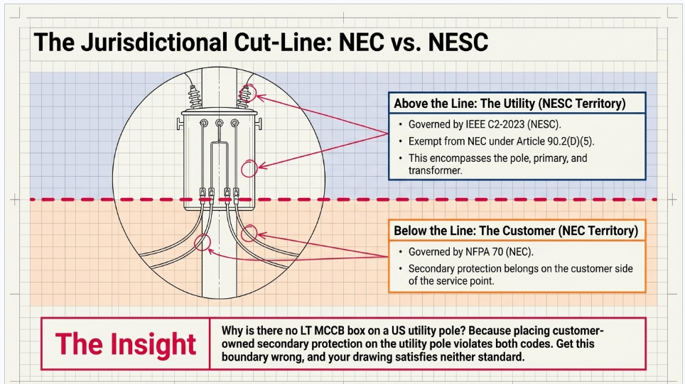
On a US utility pole, it usually isn’t there. Secondary protection lives on the customer side of the service point, in customer-owned equipment governed by the NEC (NFPA 70). The utility side stops at secondary spades, triplex, and a service drop.
That demarcation is not stylistic — it is jurisdictional. NEC 90.2(D)(5) in the 2023 NEC (90.2(B)(5) in the 2020 and earlier editions) exempts installations under the exclusive control of an electric utility, on utility-owned or leased property, for the purpose of generation, transformation, transmission, or distribution. Everything on that pole is NESC (IEEE C2-2023) territory. Everything past the service point is NEC territory, and NEC Article 450 governs the customer’s transformers, not the utility’s.
Get this boundary wrong and you produce a drawing that satisfies neither code.
7. Protection philosophy: the part that doesn’t translate at all
The rendering’s SLD implies a straightforward radial cascade. US distribution protection is more layered, and the fuse is designed around it.
Fuse links
Expulsion links per IEEE/ANSI C37.42 come in speed characteristics defined by speed ratio — the ratio of the current that melts the link in 0.1 s to the current that melts it in 300 s (600 s for links above 100 A). Type K links are fast (speed ratio 6–8, nominally 7); Type T links are slow (10–13, nominally 12). Selecting K where a utility standardizes on T, or vice versa, breaks coordination with the upstream device.
Sizing
There is no clean percentage rule, and consultants who quote one are usually quoting a rule of thumb as if it were a standard. Real practice:
- PG&E’s overhead standard states plainly that transformers are fused at approximately 2.5× nominal rating.
- Classic guidance holds that minimum blowing current should exceed roughly 200% of transformer FLA, since primary fuses cannot meaningfully protect against overload — the curves don’t match — and exist for fault clearing.
- S&C Data Bulletin 350-110, the industry selection reference, deliberately uses per-kVA lookup tables, not a multiplier, evaluating continuous peak load at 40 °C ambient, hot-load pickup up to 6× pre-interruption current, and cold-load pickup of 6× for 1 s, 3× for 10 s, and 2× for 15 minutes.
- Major utilities (JEA among them) publish direct kVA→link tables by system voltage with no percentage rule at all.
The right framing: cold-load and hot-load pickup set the floor, not full-load amps. A transformer that has been de-energized for an hour on a summer afternoon will draw multiples of FLA on restoration, and a fuse sized off FLA will nuisance-blow every time the feeder recloses.
Coordination
The pole fuse must coordinate with the upstream feeder recloser or substation relay, and the utility’s fuse-saving versus fuse-blowing philosophy determines whether the recloser’s fast curve is enabled. That decision is made at the feeder level, not the pole level — which is precisely why a pole-top detail cannot be designed in isolation from the distribution study.
Arresters
Under IEEE C62.11-2020, distribution arresters are still specified as Normal Duty or Heavy Duty (with Heavy Duty Riser as an HD variant). What changed in the 2020 harmonization with IEC 60099-4 was the retirement of line-discharge-class ratings in favor of charge and energy withstand: Qrs (repetitive single-impulse charge transfer), Qth (thermal charge transfer, for distribution arresters), and Wth (switching-impulse energy). Specifications written against the older line-discharge-class language should be updated.
8. Grounding
The rendering’s "earthing" conductor and base plate become something structurally different in the US: the pole ground is not a standalone earth electrode serving one transformer, it is one of many bonds to a continuous multigrounded neutral.
Governing rules live in NESC Section 9:
- Rule 096A — resistance to ground low enough to permit prompt operation of protective devices.
- Rule 096C — multigrounded neutral systems require a minimum of four grounds per mile.
- Rule 096D — an individual made electrode on a single-grounded system shall not exceed 25 Ω.
A note on standards misuse we see regularly in submitted packages:
IEEE Std 80-2013 is a substation grounding guide — GPR, step and touch potential inside the fenced yard — and
IEEE Std 142 (Green Book) covers industrial and commercial premises grounding. Neither is the governing document for a utility distribution pole ground. Citing IEEE 80 for a pole ground is a tell that the design was assembled from references rather than from practice.
9. If the pole serves a DER site
Increasingly, these assemblies exist to serve or interconnect distributed generation. Once generation is on the customer side of that transformer, IEEE Std 1547-2018 (with amendment 1547a-2020, which widened Category III trip-clearing settings in Table 13) governs interconnection performance, ride-through, protection, and testing. That drives anti-islanding coordination, transformer winding configuration selection, and whether a direct transfer trip or a dedicated interconnection recloser is required — none of which is visible anywhere on the original rendering, and all of which changes the pole.
Standards referenc
| Standard | Scope |
|---|---|
| ANSI/NEMA C84.1-2020 (R2025) | System and utilization voltage ratings, 60 Hz |
| IEEE C57.12.00 | General requirements, liquid-immersed transformers; BIL and preferred kVA tables |
| IEEE C57.12.20-2023 | Overhead-type distribution transformers, 500 kVA and smaller, ≤34.5 kV |
| Overhead-type distribution transformers, 500 kVA and smaller, ≤34.5 kV | Metal-oxide surge arresters for AC circuits >1 kV |
| IEEE/ANSI C37.42 | High-voltage fuses, cutouts, and accessories |
| NESC — IEEE C2-2023 | Overhead line safety, clearances, strength, grounding |
| ANSI C119.4-2022 | Aluminum/copper distribution and transmission connectors |
| ANSI C29 series | Porcelain, glass, and composite insulators |
| ANSI O5.1-2022 | Wood poles — specifications and dimensions |
| ASTM C1089-19 (R2025) | Spun cast prestressed concrete poles |
| RUS Bulletin 1724E-150 | Design guide for rural electric distribution lines |
| IEEE Std 1547-2018 / 1547a-2020 | DER interconnection and interoperability |
| NEC (NFPA 70) 90.2 | Utility exemption; NEC/NESC jurisdictional boundary |
losing
The original rendering is a good teaching drawing. It is also a reminder that a distribution assembly is not a parts list — it is the physical expression of a system philosophy. Change the neutral from three-wire to multigrounded, the frequency from 50 to 60 Hz, the governing code from IS/CBIP to NESC, and the protection basis from a secondary MCCB to a coordinated feeder recloser, and you have not adapted a design. You have replaced it.
At Keentel Engineering, distribution-class assets like these show up constantly at the edges of the work we do — auxiliary and station service at collector substations, gen-tie taps, POI interconnection packages, and utility service to solar, wind, and BESS sites. The interfaces between the utility distribution system and the project are where interconnection schedules slip, and they slip for exactly the reasons above: a clearance applied off the wrong voltage basis, a fuse sized off FLA instead of cold-load pickup, an NEC citation where a NESC rule belonged.
If you have a pole-top, service, or POI detail that needs to be right the first time, we would be glad to look at it.
KEENTEL ENGINEERING
Tampa, FL · Austin, TX · Sacramento, CA · Baltimore, MD
keentelengineering.com · contact@keentelengineering.com · 813-389-7871
Engineering note: standards editions, rule numbers, and clearance values cited here were verified against current published sources at time of writing. Always confirm against the governing edition adopted in your jurisdiction and the serving utility’s own construction standards, which frequently exceed code minimums.

About the Author:
Sandip "Sonny" R. Patel, P.E.
IEEE Senior Member · Founder & CEO, Keentel Engineering
In 1995, Sonny Patel earned his Electrical Engineering degree from the University of Illinois. But degrees don't build legacies — action does.
For three decades, he has worked the power industry from every side of the table: 16 years as a utility engineer at Exelon/Commonwealth Edison; generation leadership across hydroelectric, industrial steam turbine, and a 9 GW renewable fleet; NERC Regional Entity Senior Compliance Engineer and Audit Team Lead, auditing some of the nation's largest utilities; and testing and commissioning lead on equipment up to 765 kV — the very top of the North American grid.Utility. Generator. Regulator. Consultant. Few engineers have seen all four seats. Fewer still have sat in them.
His experience spans nuclear, hydro, conventional generation, renewables, oil and gas, mining — and today's data centers, where he is authoring a three-book series on data center design. He is a Licensed Professional Engineer in six states and a Licensed Electrical Contractor in Florida (Unlimited EC) — he doesn't just design the work; he's qualified to stand behind its execution.Today, as Founder and CEO of Keentel Engineering, Sonny leads a nationwide team of engineers delivering substation design, power system studies, NERC compliance, and commissioning — done right, coast to coast.Three decades. Every side of the table. One standard: accountable engineering.
Services

Let's Discuss Your Project
Let's book a call to discuss your electrical engineering project that we can help you with.
About the Author:
Sandip "Sonny" R. Patel, P.E.
IEEE Senior Member · Founder & CEO, Keentel Engineering
In 1995, Sonny Patel earned his Electrical Engineering degree from the University of Illinois. But degrees don't build legacies — action does.
For three decades, he has worked the power industry from every side of the table: 16 years as a utility engineer at Exelon/Commonwealth Edison; generation leadership across hydroelectric, industrial steam turbine, and a 9 GW renewable fleet; NERC Regional Entity Senior Compliance Engineer and Audit Team Lead, auditing some of the nation's largest utilities; and testing and commissioning lead on equipment up to 765 kV — the very top of the North American grid.
Utility. Generator. Regulator. Consultant. Few engineers have seen all four seats. Fewer still have sat in them.
His experience spans nuclear, hydro, conventional generation, renewables, oil and gas, mining — and today's data centers, where he is authoring a three-book series on data center design. He is a Licensed Professional Engineer in six states and a Licensed Electrical Contractor in Florida (Unlimited EC) — he doesn't just design the work; he's qualified to stand behind its execution.
Today, as Founder and CEO of Keentel Engineering, Sonny leads a nationwide team of engineers delivering substation design, power system studies, NERC compliance, and commissioning — done right, coast to coast.Three decades. Every side of the table. One standard: accountable engineering.
Leave a Comment
Thank you for contacting us.
We will get back to you as soon as possible.
We will get back to you as soon as possible.
Oops, there was an error sending your message.
Please try again later.
Please try again later.
Related Posts

By SANDIP R PATEL
•
September 30, 2026
Learn NERC and ERCOT compliance requirements for natural gas power plants, including GO/GOP obligations, O&P standards, GADS reporting, and audits.

By SANDIP R PATEL
•
September 26, 2026
Learn how to prepare a MISO large-load interconnection package, including PSS®E models, BESS smoothing, harmonic data and transmission-owner requirements.

By SANDIP R PATEL
•
September 26, 2026
Learn where storage belongs in an 800 VDC AI data center, including capacitors, flywheels, BESS, fault current, protection, grounding, and EMT design.

By SANDIP R PATEL
•
September 26, 2026
Learn how SPP’s HILL and HILLGA framework works for large-load projects, including studies, BTM generation, modeling, EMT requirements, and firm service.

By SANDIP R PATEL
•
September 25, 2026
Learn how IBR time synchronization, IEEE 2800, IRIG-B verification, and PTP solutions help meet disturbance monitoring compliance requirements.

By SANDIP R PATEL
•
September 24, 2026
Learn why continuing technical training matters in power engineering, including standards, software skills, PDH requirements, and career growth.
By SANDIP R PATEL
•
September 22, 2026
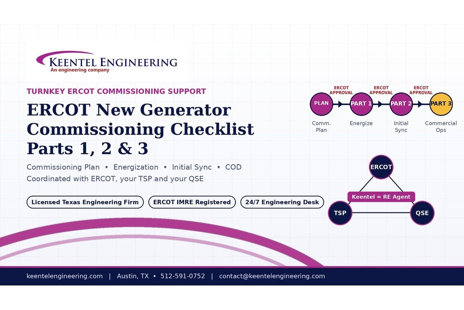
2026 ERCOT commissioning guide covering the Commissioning Plan, Checklist Parts 1–3, BESS requirements, TSP/QSE coordination, field testing and COD.

By SANDIP R PATEL
•
September 22, 2026
Learn PRC-030-1 R1 event detection requirements for inverter-based resources, SEL platforms, disturbance monitoring, and audit-ready compliance.
By SANDIP R PATEL
•
September 22, 2026
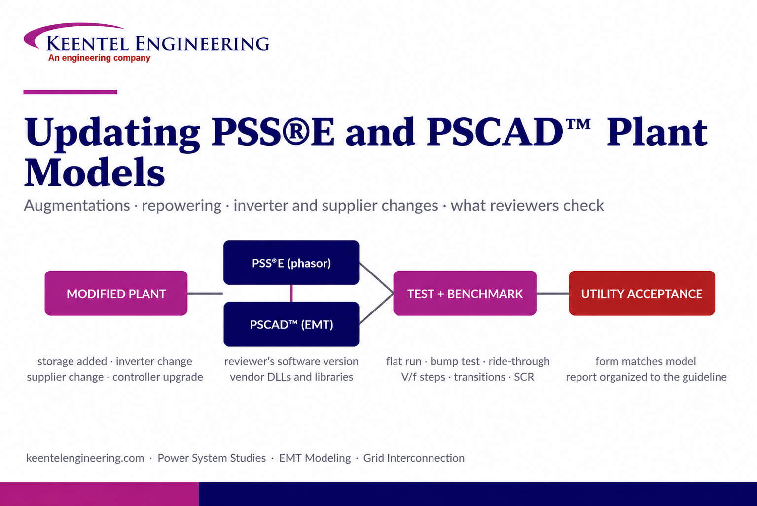
Learn how PSS®E and PSCAD™ model updates support plant augmentations, repowering, equipment changes, testing, benchmarking, and grid compliance.





