
A Coordinated Electric System Interconnection Review—the utility’s deep-dive on technical and cost impacts of your project.
Challenge: Frequent false tripping using conventional electromechanical relays
Solution: SEL-487E integration with multi-terminal differential protection and dynamic inrush restraint
Result: 90% reduction in false trips, saving over $250,000 in downtime
ERCOT enforces all of the above through simulation, which means your model is your compliance case. The bar is now high:
- Whole-facility scope. The model must represent everything the IT load, the UPS and power conversion, the cooling plant, the protection and control systems in formats compatible with ERCOT's study platforms (PSS/E, PSCAD, TSAT).
- Real control loops, not approximations. Generic textbook representations are unacceptable. The model must capture the actual inner control behavior of your power electronics.
- Hardware-validated converter models. For electronic loads, the PSCAD model must be benchmarked against actual hardware testing including voltage ride-through and subsynchronous response. A model assembled from standard PSCAD library blocks fails by definition, because a generic block has never been tested against your vendor's hardware. The good news: validation is a hardware-type test, so results for a given converter product are reusable across every facility that uses it.
- Format migration. Facilities that previously submitted the older composite load model (CMLD) format must transition to EPRI's PERC1 format.
- Three checkpoints. Models are reviewed before the stability study begins (no model, no study), before each quarterly stability assessment, and for electronic loads one final time before energization, when you must submit as-built models with a documented comparison against the previously studied data and a sworn attestation that the model matches actual field settings. ERCOT's review takes 10 business days, extendable by 20 put it on your critical path.
- A living obligation. Change your technology, controls, or relay settings in a way that affects ride-through including converting a crypto mining site to an AI data center — and you've triggered a new interconnection study, even if your megawatts don't change.
| Parameter | Detail |
|---|---|
| System | 230 kV / 138 kV transmission corridors, wind and wet-snow icing exposure |
| Data basis | 15 years of minute-resolution forced-outage records + regional weather observations |
| Core methods | Event grouping, MVA performance curves, time-to-95%-restore, area outage rate curves, fragility modeling, rerun-history benefits, exceedance and log-domain risk metrics |
| Headline result | ≈85% of maximum resilience benefit at 60% of original capital; worst-event restoration window cut from 11 days to 5 in rerun-history terms |
| Decision supported | Capital portfolio selection; resilience plan filing; post-investment verification framework |
| System / Topic | Governing Standard(s) | What It Controls |
|---|---|---|
| Overall plant electrical distribution | IEEE 141 (Red Book); IEEE 666 | Distribution architecture, voltage selection, design of generating station auxiliary service systems |
| Power system studies | IEEE 399 (Brown Book); IEEE 551 | Load flow, symmetrical/asymmetrical short circuit, motor starting methodologies down to the lowest LV panelboard |
| Protection & coordination | IEEE 242 (Buff Book); IEEE 3004.5; IEEE C37 series | Generator relaying (21, 59N, 87G), time-current coordination, selective clearing between LV and MV tiers |
| GSU / UAT / SST transformers | IEEE C57.12.00 and C57 family | Transformer ratings, impedance, testing, loading |
| HV switchyard breakers | IEEE C37.06 | AC high-voltage circuit breaker preferred ratings |
| MV switchgear (13.8 kV) | IEEE C37.20.2; IEEE C37.20.7 | Metal-clad construction, compartmentalization, vacuum breakers; arc-resistant design with plenum venting |
| MV cable | UL 1072; ICEA S-93-639 (NEMA WC 74) | Type MV-105 shielded cable, 133% insulation level for HRG systems |
| LV switchgear (480 V) | IEEE C37.13; UL 1558 | Metal-enclosed LV power circuit breaker switchgear to 635 V, draw-out ACBs with electronic trip units |
| Motor control centers | UL 845; NEMA ICS 18 | LV-MCC construction, MCCB/MCP protection for motors under ~200 HP |
| Motors | NEMA MG-1 | Motor performance, starting characteristics, service factors |
| DC & battery systems | IEEE 485; IEEE 946 | Lead-acid battery sizing (125/250 VDC), DC auxiliary system design |
| Grounding | IEEE 80; IEEE 142 (Green Book) | Ground grid step/touch potential limits; system grounding including high-resistance grounding |
| Lightning protection | IEEE 998 | Direct-stroke shielding of switchyard and outdoor generator structures |
| Arc flash & electrical safety | IEEE 1584; NFPA 70E | Incident energy calculation; worker safety boundaries and PPE |
| Fire protection | NFPA 850 | Fire protection and risk management for combustion turbine generating plants |
| Installation code | NEC (NFPA 70); NESC | Wiring methods inside the plant fence; overhead/outdoor clearances at the switchyard |
| Interconnection & compliance | FERC LGIP; NERC MOD-025/026/027, PRC-019/024/029, FAC-008 | Interconnection process, model validation, protection/ride-through coordination, facility ratings |
| IFC / Construction Deliverable | Purpose |
|---|---|
| Stamped IFC packages | Legal basis for construction; P.E. responsible charge |
| Final relay settings & TCCs | Protection as-installed matches the coordination study |
| Calculation archive | Owner records; NERC audit evidence trail |
| Commissioning procedures | Safe, sequenced energization; MOD field testing |
| Construction support | RFIs, field changes, FAT/SAT witness |
| As-builts & model handoff | Operating baseline; future study currency |
| Metric | Outcome |
|---|---|
| Defects found pre-occupancy | Three topology defects and one settings-mismatch family corrected before load migration; the shared-switchboard defect alone would have invalidated the concurrently-maintainable claim on day one |
| IST findings | Fourteen additional discrepancies surfaced under scenario testing (control logic, alarm mapping, one generator sequencing fault) — all closed before handover instead of during operations |
| Black-building test | Passed on second execution; the first attempt exposed the generator sequencing fault under true block load, exactly the failure the compressed plan would never have found |
| Handover quality | Operations team certified on the actual failure scenarios; corrected EOPs and settings documentation delivered as controlled documents |
| Business outcome | Occupancy proceeded three weeks behind the original date — against an independent estimate that the uncorrected sequencing fault carried a high probability of a full facility outage within the first year |
Part 2 — Frequently Asked Questions: Large Load Interconnection
An electric grid must remain in continuous balance — generation onto the grid must equal consumption from it at every instant. PJM achieves this balance, and prices it, through a layered market architecture. Each layer operates on a different time horizon, and each one touches project economics differently.
| Domain | Key Standards / Codes | What They Govern |
|---|---|---|
| Fire safety | NFPA 855; UL 9540 / UL 9540A | Installation requirements, separation, gas management; system safety listing and thermal-runaway fire testing |
| Grid interconnection | IEEE 1547 (distribution); IEEE 2800 (transmission IBRs) | Ride-through, reactive capability, power quality, and performance at the point of interconnection |
| Power quality | IEEE 519 | Harmonic distortion limits at the PCC |
| Protection & grounding | IEEE 80 / 81 / 142; C37 series | Grounding system design and testing; protective relaying |
| Reliability compliance | NERC standards (incl. PRC ride-through requirements) | Registered-entity obligations for grid-connected storage |
Gas-Insulated Substations: What the Component Diagrams Leave Out
Aug 22, 2026 | Blog
Substation Design | Technical Guide, FAQ and Case Studies | August 2026
There is a widely shared infographic that labels the parts of a GIS bay — bus, circuit breaker, disconnector, combined disconnector/earthing switch, CT, VT — and gives each a two-line description. As an orientation slide it does its job. Most engineers who have never stood next to a GIS could point at the right pieces after reading it.
But one of its statements is not merely imprecise. It describes the safety property that GIS does not have, and it describes it as the reason you would use the equipment. If that sentence made it into a switching procedure, it would put someone at risk.
This article does three things. It corrects what the popular diagrams get wrong, on IEEE C37.122-series and IEC 62271 basis. It covers the GIS-specific engineering the diagrams omit entirely — gas zoning, density monitoring, very fast transients, enclosure currents, partial discharge, decomposition byproducts. And it deals with the question that now dominates every GIS procurement in North America: what happens when you cannot buy SF₆ equipment any more.
1. What the diagram gets right
Credit first, because the framework is sound.
A GIS bay really is the same functional set as an air-insulated bay — bus, breaker, disconnectors, earthing switches, instrument transformers — with two differences: the live parts sit inside grounded aluminum enclosures filled with an insulating gas at a few bar, and the dielectric strength of that arrangement lets you shrink the phase-to-phase and phase-to-ground clearances by roughly an order of magnitude.
The diagram is also right that:
- The circuit breaker interrupts load and fault current, and in a conventional GIS the same gas that insulates also quenches the arc.
- The disconnector is a no-load device. It is not rated to break load current, and operating one under load is a well-known way to destroy a GIS bay.
- The combined disconnector/earthing switch (DS/ES) saves length and gas volume by putting two functions in one enclosure — the single most common space-saving move in modern GIS design.
- The make-proof earthing switch is a real and distinct device class, rated to close onto a fault without welding shut.
- CTs and VTs feed protection and metering.
All correct. Now the parts that are not.
2. The error that matters: "visible isolation"
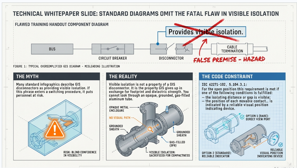
The diagram states that the disconnector "provides visible isolation of equipment." In a GIS, that is exactly backwards — and the standard that governs disconnectors says so, clearly, in a sentence worth reading twice.
IEC 62271-102, subclause 5.104.3.1, "Indication of position":
"It shall be possible to know the operating position of the disconnector or earthing switch. For the open position this requirement is met if one of the following conditions is fulfilled: — the isolating distance or gap is visible; — the position of each movable contact ensuring the isolating distance or gap is indicated by a reliable visual position indicating device."
Read the structure. The standard gives two alternative ways to satisfy a single requirement — knowing the position. Air-insulated switchgear satisfies it the first way: you look up and see the gap. A GIS disconnector is a moving contact inside an opaque, grounded, gas-filled aluminum enclosure. It cannot satisfy the first condition and must satisfy the second.
Visible isolation is not a property of a GIS disconnector. It is the property GIS gives up in exchange for everything else it provides.
What replaces it
This is not a weakness — it is a different, and arguably more rigorous, safety architecture. Four elements do the work that a visible gap does in AIS.
A position indicator that is mechanically coupled, not inferred. The normative annex of IEC 62271-102 does not treat "reliable" as a marketing word. The kinematic chain between the moving contact and the indicator must be a continuous mechanical connection to ensure a positively driven operation, must have sufficient mechanical strength, and must indicate open or closed only after the moving contacts have actually reached that position. A strain-limiting device is not permitted anywhere in that chain. The indicator is not a lamp driven by an auxiliary switch — it is a mechanical extension of the contact itself, type-tested to prove it.
Interlocking. Mechanical and electrical interlocks between breaker, disconnector and earthing switch prevent the sequence errors that cause GIS failures. Manual operation is possible only under electrical interlock release. The feeder earthing switch is interlocked with its breaker and disconnector.
Voltage presence verification. Interlocking the earthing switch against line VT secondary voltage through undervoltage relay contacts proves the circuit is dead before the earthing switch can close.
The integrated earthing switch itself. In AIS, the visible gap is the proof of the safe state. In GIS, the applied earth is the proof. That is a stronger guarantee, because an earthing switch does not merely separate you from the source — it holds the conductor at ground potential against induced and capacitively coupled voltage.
Some GIS designs offer inspection windows, and some utilities specify them or add camera monitoring of the viewport. Neither IEC 62271-102 nor IEC 62271-203 requires them. They are a specification option, not a code baseline, and they should never be the sole basis of a switching procedure.
The practical consequence. If your lockout/tagout or switching procedure contains the phrase "verify visible break," it was written for air-insulated equipment and it cannot be executed on a GIS. It must be rewritten around position indication, interlock status, applied earths, and voltage verification. See Case Study 2 — this is not hypothetical.
3. Four more corrections
"ES = Earthing transformer." The diagram's legend expands ES as earthing transformer. ES is the earthing switch — the device drawn in the picture. An earthing transformer is an entirely different animal: a zig-zag or wye-delta transformer that creates a neutral point on a delta or ungrounded system so it can be resistance- or reactance-grounded. Putting one term where the other belongs is the kind of error that survives into a bill of materials.
A box titled "DS - Circuit Breaker." It contains the disconnector's description — visible isolation, no-load operation, maintenance safety — duplicating the DS box two panels over. It is a mislabel, not a device.
Two identical CT panels. "CT - Current Transformer" and "CT - Current" carry the same three bullets. Space that could have described gas zoning or interlocking.
And the VT is drawn without an isolating disconnector. In practice, GIS VT compartments are frequently separated by a disconnector or removable link so the VT can be isolated for testing without de-gassing the bus. Whether you need one is a design decision, but it belongs on the diagram.
4. What the diagrams leave out entirely
Everything above is about labels. This section is about engineering, and it is where GIS actually differs from a metal box full of familiar devices.
4.1 Gas compartments are a design decision, not a detail
A GIS is not one volume of gas. It is divided into gas compartments separated by gas-tight barrier insulators, and the partitioning scheme determines what has to be de-gassed, opened, evacuated and refilled to work on any given component — and therefore how much of the substation goes out of service for any given job.
Segment too coarsely and a single leak or a single component failure takes an entire bus section out. Segment too finely and you add barrier insulators, gas zones, density monitors, cost and leak paths. This is one of the highest-leverage decisions in GIS specification, it is invisible on the single-line diagram, and it is almost never discussed in component overviews. See Case Study 3.
4.2 Density monitoring, not pressure gauges
GIS uses temperature-compensated density monitors, not pressure gauges. The reason is simple: pressure in a sealed compartment swings with ambient temperature through the day while the quantity of gas is unchanged. A pressure reading cannot distinguish a cold morning from a slow leak. Density monitors measure pressure and temperature together and compute density against manufacturer correction curves.
Each gas zone gets a two-stage scheme: stage 1 alarm (top up at the next opportunity) and stage 2 lockout (block operation or trip and isolate). Setpoints are compartment- and manufacturer-specific and should never be copied from a generic table.
The permissible leakage rate has tightened. IEC 62271-203 Edition 3.0 (2022) states in its foreword that "the tightness requirements for type tests for gasses with GWP > 1 000 has been reduced from 0,5 % to 0,1 % per year per gas compartment." If your specification still calls for 0.5% per year on SF₆ equipment, it is citing the previous edition.
4.3 Very fast transient overvoltages (VFTO)
This is a GIS-specific phenomenon with no real air-insulated equivalent. When a GIS disconnector switches a small capacitive current, the restrikes across the slowly moving contacts launch travelling waves between the inner conductor and the enclosure. Because the geometry is a low-loss coaxial line, those waves bounce.
The result is a transient with a rise time in the nanosecond range — roughly 10 to 1,000 ns depending on gas pressure — and a peak typically in the range of 1.4 to 2.0 per unit of rated voltage. Standard lightning impulse testing does not represent this waveform, because the rise time is two orders of magnitude faster.
VFTO matters for insulation coordination inside the GIS, for transformer windings connected directly to a GIS without intervening cable, and for the secondary systems that see the transient couple out. IEC 62271-102 Annex F addresses disconnector switching requirements at 72.5 kV and above; IEC 60071-1 covers insulation coordination; CIGRE has treated it extensively in WG A3.22, A3.28 and C4.306 and Technical Brochures 362, 400 and 456.
4.4 Enclosure currents and transient enclosure voltage
The aluminum enclosure of a GIS is not passive. It carries an induced return current that can reach up to about 90% of the conductor current, flowing in the opposite direction. That is a feature, not a problem — the near-cancellation of the magnetic field is one reason GIS has such low external field — but it only works if the enclosure is electrically continuous.
Every module must be bonded, by flange connections or external shunts, into a continuous enclosure. Where that continuity is broken — at discontinuities, at expansion joints, at air-to-gas bushings — travelling waves can produce transient enclosure voltage (TEV). TEV is generally not a direct shock hazard to personnel, but it will produce electrostatic sparks if the multipoint grounding system is not correctly installed, and those sparks are both a personnel startle hazard and a nuisance-trip source for nearby secondary wiring.
GIS grounding is a multipoint scheme by design, and it interacts with — but is not the same as — the station ground grid analysis under IEEE Std 80.
4.5 Partial discharge monitoring
GIS is unusually intolerant of small internal defects. A free metallic particle a few millimetres long, a protrusion on a conductor, a floating electrode, a void or delamination in a cast spacer — any of these can initiate a flashover in a system whose dielectric margin is engineered tight.
The industry answer is UHF partial discharge monitoring, using sensors coupled into the enclosure. Per IEC TS 62478, the UHF band is nominally 300 MHz to 3 GHz; commercial GIS instruments typically work in a sub-band of that. Sensitivity verification is covered by CIGRE TB 654 (WG D1.25), and the more recent CIGRE TB 933 (WG D1.66) addresses requirements and application of UHF PD monitoring systems for gas-insulated systems.
PD monitoring is now routine on new transmission-class GIS and is one of the strongest arguments for the technology: an internal defect that would be invisible in an AIS yard is detectable, trendable and locatable in a GIS.
4.6 Decomposition byproducts and personnel safety
SF₆ itself is chemically inert and non-toxic. Arced SF₆ is neither.
The byproducts of arcing and of arcing against silica-filled epoxy spacers include SOF₂ (thionyl fluoride), SO₂F₂ (sulfuryl fluoride), SF₄ (sulfur tetrafluoride), S₂F₁₀ (disulfur decafluoride), HF (hydrogen fluoride), SiF₄ (silicon tetrafluoride), SO₂, and solid metal fluorides as a fine powder. EPA's own guidance identifies S₂F₁₀ as the most toxic of these, on the order of 43 times more toxic than the others.
OSHA permissible exposure limits apply to several of these directly — S₂F₁₀ at a 0.025 ppm TWA, SF₄ at a 0.1 ppm ceiling, HF at 3 ppm TWA, SO₂ at 2 ppm TWA. Protective clothing and an approved respirator are required where decomposition products may be present, and the solid fluoride powder must be handled as a contaminant, not swept up.
There is no SF₆-specific OSHA rule, but SF₆ does carry an OSHA PEL of 1,000 ppm — and the practical hazard is not toxicity, it is asphyxiation. SF₆ is roughly five times heavier than air. It pools in cable basements, trenches, pits and the low corners of GIS buildings. Confined-space procedures and oxygen monitoring belong in the design of the building, not just in the O&M manual.
IEEE C37.122.3-2024 is the current gas-handling guide. Note the edition — it superseded the 2011 version, and specifications still calling for C37.122.3-2011 are two revisions behind on a document that has been substantially updated as alternative gases entered service.
5. The SF₆ question
Every popular GIS diagram says the same thing: the equipment uses SF₆ for insulation and arc quenching. That was a complete answer in 2015. In 2026 it is the beginning of a procurement conversation, and getting it wrong can strand a substation design.
5.1 Why the pressure exists
SF₆ is the most potent greenhouse gas the IPCC has assessed. Its 100-year global warming potential is:
| IPCC Assessment Report | SF₆ GWP₁₀₀ |
|---|---|
| AR4 | 22,800 |
| AR5 | 23,500 |
| AR6 | 24,300 |
Its atmospheric lifetime is approximately 3,200 years. A kilogram released today is still working in the year 5200.
Which number you use depends on the regime. The US EPA Greenhouse Gas Reporting Program uses AR4 (22,800); the US national GHG inventory uses AR5 (23,500) under UNFCCC rules; EU Regulation 2024/573 uses AR6 (24,300), which is the figure that now appears on mandatory F-gas equipment labels.
5.2 What US federal law actually requires
Less than most people assume, and it is worth being precise because vendors are not always.
40 CFR Part 98, Subpart DD — "Electrical Transmission and Distribution Equipment Use" — requires electric power systems to report emissions of fluorinated GHGs from transmission and distribution equipment, where the facility meets the general 25,000 metric ton CO₂e per year threshold. Reported data includes nameplate capacity of insulating gas, gas acquired and disbursed, and transmission and distribution line miles.
There is no federal EPA ban on SF₆ in electrical equipment. Subpart DD establishes reporting requirements only — no operational bans, no emission limits. And the voluntary EPA SF₆ Emission Reduction Partnership (later the Electric Power Systems Partnership) is no longer active; its resources are archived.
If a vendor tells you federal law is forcing your hand, it is not. State law and, increasingly, corporate ESG commitments are.
5.3 California CARB — the schedule that is actually binding
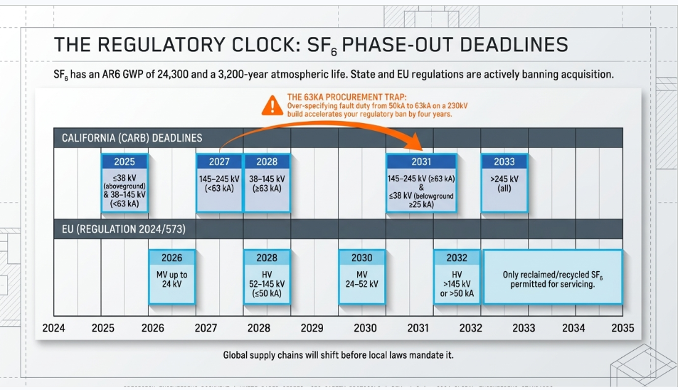
California adopted its Regulation for Reducing Sulfur Hexafluoride Emissions from Gas Insulated Switchgear in October 2020, effective January 2022, codified at 17 CCR §§95350–95359.1. Section 95352 sets a phase-out: from the dates below, no person may acquire SF₆ gas-insulated equipment for use in California.
38 kV and below (Table 1):
| Configuration | Short-circuit rating | Phase-out date |
|---|---|---|
| Aboveground, below 38 kV | all | 1 Jan 2025 |
| Aboveground, 38 kV | all | 1 Jan 2028 |
| Belowground, 38 kV and below | < 25 kA | 1 Jan 2025 |
| Belowground, 38 kV and below | ≥ 25 kA | 1 Jan 2031 |
Above 38 kV (Table 2):
| Voltage | Short-circuit rating | Phase-out date |
|---|---|---|
| 38 < kV ≤ 145 | < 63 kA | 1 Jan 2025 |
| 38 < kV ≤ 145 | ≥ 63 kA | 1 Jan 2028 |
| 145 < kV ≤ 245 | < 63 kA | 1 Jan 2027 |
| 145 < kV ≤ 245 | ≥ 63 kA | 1 Jan 2031 |
| > 245 kV | all | 1 Jan 2033 |
Converting non-SF₆ equipment to SF₆ is also prohibited from the applicable date. Replacement parts for existing equipment are exempt. Annual reports are due to CARB by 1 June.
Note the breakpoints: 38 / 145 / 245 kV, with sub-thresholds at 25 kA and 63 kA. They are not the same as the EU's. Do not blend the two schedules — a specification written against the wrong set of numbers will be wrong at exactly the voltage classes where it matters.
5.4 The EU schedule, for anyone with a global supply chain
Regulation (EU) 2024/573 prohibits placing on the market:
| Equipment | From |
|---|---|
| MV switchgear up to and including 24 kV | 1 Jan 2026 |
| MV switchgear above 24 kV up to and including 52 kV | 1 Jan 2030 |
| HV switchgear 52 kV to 145 kV and up to 50 kA short-circuit | 1 Jan 2028 |
| HV switchgear above 145 kV or above 50 kA, GWP ≥ 1 | 1 Jan 2032 |
Plus a date that catches everyone by surprise: from 1 January 2035, only reclaimed or recycled SF₆ may be used for maintenance or servicing of electrical switchgear.
Derogations exist under Articles 13(11) and 13(12) where suitable alternatives are unavailable or technically infeasible. Repair and servicing of existing equipment is not caught by the placing-on-the-market prohibitions.
Why does this matter to a US project? Because the manufacturers are global. Product lines are being redesigned to the EU dates, and the SF₆ variant of a given GIS family may be discontinued well before your local regulation requires it.
5.5 The alternatives, honestly assessed
Three technologies are in commercial play, and they are not equivalent.
Vacuum interrupter plus clean air. Siemens Energy's blue portfolio uses a vacuum interrupter for switching and clean air — nitrogen and oxygen only — for insulation. GWP of zero, no fluorinated gas at all. This is the cleanest answer where it is available. Commercially available at 72.5 kV (8VM3, 8VM1) and 145 kV (8VN1). Be precise about the upper end: 420 kV blue GIS is not in commercial service. It is an EU LIFE demonstration project launched October 2024 running to September 2028, with a single pilot bay at an ELIA substation in Belgium.
Fluoronitrile (C4-FN) mixtures. C4-FN — perfluoroisobutyronitrile, CAS 42532-60-5 — is used diluted in CO₂ and O₂ because it liquefies at −4.7 °C pure. Typical HV mixtures run 3.5–5% C4-FN with 10–13% O₂, balance CO₂, rated to −25 °C or −30 °C. GE Vernova markets it as g3, with a mixture GWP around 327 versus SF₆'s 24,300 — roughly a 99% reduction. Hitachi Energy's EconiQ is also C4-FN based, including the ELK-3 420 kV GIS at 63 kA. Track record at the top end: the world's first SF₆-free 420 kV g3 GIL was energized at National Grid's Sellindge substation in April 2017; a 420 kV g3 circuit breaker for GIS was unveiled in August 2024.
The practical summary today: vacuum plus clean air is proven and commercial to 145 kV; C4-FN mixtures are the only route currently offered at 420 kV and above.
5.6 The question nobody is asking loudly enough
C4-FN is a PFAS. Any molecule with more than two carbon atoms bonded to fluorine falls inside the definition, and C₄F₇N does.
The ECHA universal PFAS restriction is live: a narrowed proposal was published in August 2025, committee opinions are expected at the end of 2026, and a Commission decision is possible in 2027. It covers 21 sectors including energy, with sector derogations of five to thirteen and a half years.
And the supply chain has already moved. 3M announced in December 2022 that it would exit all PFAS manufacturing by the end of 2025 — which covers the Novec line, including Novec 4710 (C4-FN) and Novec 5110 (C5-FK), the additives in the leading fluorinated alternatives.
None of this means C4-FN equipment is a bad choice today. It does mean that a utility replacing an SF₆ fleet with a fluorinated alternative is making a second gas-transition decision, not a final one, and should say so in its asset strategy. Where the voltage class allows it, vacuum plus clean air avoids the question entirely.
6. GIS or AIS?
The decision is rarely about the equipment. It is about the site.
| Driver | Favors |
|---|---|
| Land cost or availability | GIS — commonly cited at roughly a tenth of the AIS footprint, with 70–90% reduction typical |
| Coastal salt, industrial pollution, desert dust | GIS — live parts are sealed away from the environment |
| Flood and hurricane exposure | GIS — elevated indoor installation is practical |
| High altitude | GIS — sealed enclosure is insensitive to air-density derating |
| Extreme cold or heat | GIS — indoor installation decouples from ambient |
| Seismic zones | Either — but qualification is explicit; see below |
| Straightforward greenfield rural site | AIS — lower capital cost, simpler maintenance, no gas handling |
| SF₆ regulatory exposure | Depends — non-SF₆ GIS resolves it; AIS avoids gas entirely |
Historically only about 2 to 5% of new US substations were built as GIS, with the cost case strengthening as voltage rises. That share is climbing, driven by urban load growth, land constraints and resiliency requirements.
Seismic qualification. IEEE Std 693-2018 (with amendment 693a-2024) is the US recommended practice for seismic design of substations, defining Low, Moderate and High qualification levels. But the standard written specifically for this equipment is IEC 62271-207, "Seismic qualification for gas-insulated switchgear assemblies for rated voltages above 52 kV." It uses the same three levels, harmonized with IEEE 693, and permits site-specific spectra. On a GIS project, specify both.
Arc flash — and a trap. IEEE Std 1584-2018 applies only from 208 V to 15 kV. Above 15 kV it is outside its range of validity and should not be used to calculate incident energy. For enclosed switchgear at 52 kV and below, IEEE C37.20.7-2024, "Recommended Practice for Testing Switchgear Rated Up to 52 kV for Internal Arcing Faults," governs arc-resistant construction testing. Internal Arc Classification with accessibility types — the IAC/A/B and F/L/R designations — is defined in IEC 62271-200 for MV switchgear at 52 kV and below, not in IEC 62271-203. NFPA 70E requires that an assessment be performed; it does not prescribe the method above 15 kV.
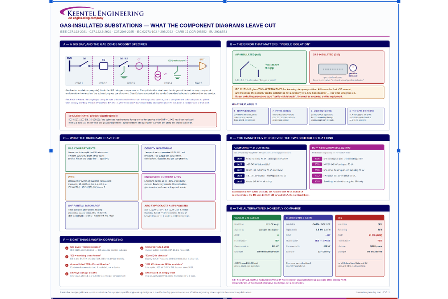
Figure 1, on the following page, summarizes the whole picture: the bay and its gas zones, the isolation question, what the diagrams omit, the two SF₆ schedules, and the alternatives compared.
FIGURE 1
— Gas-insulated substations: the bay and its gas zones, the isolation question, what the diagrams omit, the SF₆ schedules, and the alternatives
Illustrative design guidance — not a substitute for a project-specific engineering design or a qualified safety procedure review.
7. Eight things worth correcting
1. GIS disconnectors do not provide visible isolation. IEC 62271-102 5.104.3.1 offers a visible gap or a reliable visual position indicating device; GIS necessarily uses the second.
2. ES is the earthing switch, not an earthing transformer.
3. A panel titled "DS – Circuit Breaker" containing disconnector text is a mislabel.
4. The permissible leakage rate for SF₆ GIS under IEC 62271-203 Ed. 3.0 is 0.1% per year per gas compartment, not the older 0.5%.
5. Cite current editions: C37.122-2021, C37.122.2-2022, C37.122.3-2024, C37.122.6-2013, C37.122.7-2021, C37.20.9-2025, IEC 62271-203:2022 Ed. 3.0. The IEC document was explicitly extended in 2022 to cover alternative gases alongside SF₆ — which is why it is the right reference for a non-SF₆ specification.
6. Hitachi EconiQ is fluoronitrile-based, not clean air. Only Siemens blue is vacuum plus clean air. Vendors' marketing names do not map to a single technology.
7. 420 kV vacuum-plus-clean-air GIS is a pilot, not a product. 420 kV C4-FN GIL has been in service since 2017.
8.
SF₆ is an asphyxiant that pools. Five times heavier than air, in trenches and cable basements. The building design has to address it.
9. Anonymized case studies
The following are anonymized and composited from typical engagements. Figures are representative of the scenarios described and have been rounded and adjusted; they do not identify any specific client or facility.
Case Study 1 — California, 230 kV: a phase-out date discovered at procurement
Situation. A California transmission owner was midway through detailed design of a 230 kV GIS addition at an existing urban substation. The design basis, written two years earlier, specified conventional SF₆ GIS with a 63 kA short-circuit rating. Long-lead procurement was scheduled to begin the following quarter.
What the analysis found. Under 17 CCR §95352 Table 2, equipment in the 145 kV to 245 kV band rated below 63 kA could no longer be acquired in California after 1 January 2027, and equipment at 63 kA and above after 1 January 2031. The project's 63 kA rating placed it in the later bracket — but only just, and the rating had been selected with margin rather than from a hard system requirement.
The short-circuit study was revisited. Available fault duty at the bus was well under 50 kA, and the 63 kA specification was inherited from a template. Had it been trimmed to a standard 50 kA rating, the project would have fallen into the 2027 bracket and the SF₆ design would have been unpurchasable before the second phase of the build.
Separately, the manufacturer's roadmap indicated the SF₆ variant of the chosen 245 kV family was scheduled for discontinuation in line with the EU 2032 date, with engineering support winding down earlier.
What was done. The design was converted to a C4-FN mixture GIS at the same voltage and current ratings. Three things had to be reworked: enclosure dimensions grew modestly, which propagated into the building layout and the crane coverage; the gas handling plan, spares strategy and technician training were rewritten around a mixture rather than a single gas; and the asset strategy was updated to record explicitly that C4-FN is a PFAS and that a second gas transition may be required within the asset's life.
Outcome. The change added roughly four months to the design phase and avoided a procurement dead end that would have surfaced during construction of phase two. The 63 kA rating was retained — but as a documented decision with a stated basis, not an inherited default.
Engineering takeaway. On a GIS project, the regulatory schedule is a design input with the same standing as the fault duty. And check whether an inherited rating is putting you in a different regulatory bracket than the system actually requires — the CARB thresholds sit at 25 kA and 63 kA, and margin you did not need can move your deadline by four years in either direction.
Case Study 2 — Industrial plant, 115 kV: the procedure that could not be performed
Situation. A process plant replaced a congested outdoor 115 kV air-insulated switchyard with an indoor GIS. Commissioning went well. Six weeks into operation, a maintenance crew preparing to work on a feeder cable stopped work and escalated, because they could not complete step 7 of the switching procedure.
What the analysis found. The plant's high-voltage switching and lockout/tagout procedure — carried over from the AIS installation with the equipment names updated — required the switching operator to "visually verify the open disconnect blades before applying grounds."
There were no blades to see. The disconnector was inside a grounded aluminum enclosure. The crew, correctly, refused to proceed on the basis of a step they could not perform, and the escalation was the system working as intended.
Review found the deeper problem. The procedure had been treated as a document to be find-and-replaced rather than rewritten, and the same assumption ran through several other documents: the operator training material, the permit-to-work form, and a contractor safety briefing that instructed visiting crews to "confirm visible isolation."
What was done. The switching procedure was rewritten from the equipment up, around the four things that actually establish the safe state on a GIS: the mechanically coupled position indicator and what a compliant indicator is; interlock status and the electrical release conditions; applied earthing switches as the physical proof; and voltage verification through the VT undervoltage interlock. Operator training was rebuilt around position indication and interlocking rather than visual confirmation. The local control cabinet mimic was re-labelled to make position indication unambiguous at a glance.
The plant also added a step that has no AIS equivalent — confirming the gas density status of the relevant compartments before any operation, because a compartment in stage-2 lockout will not operate and the crew needs to know that before they are standing at the panel rather than after.
Outcome. No injury and no incident. The cost was a procedure rewrite and a retraining cycle. The near-miss report is now part of the plant's onboarding for the GIS.
Engineering takeaway. The most dangerous document on an AIS-to-GIS conversion is the procedure that was updated instead of rewritten. "Visible isolation" is not a phrase that can be find-and-replaced — the safety architecture underneath it is different, and every document that assumed a visible break has to be rebuilt on position indication, interlocks and applied earths.
Case Study 3 — Utility, 138 kV: one leak, one bus, one long outage
Situation. A utility's 138 kV GIS lost an entire bus section for eleven days after a slow gas leak developed at a flange on a single bay. The equipment performed exactly as designed. The design was the problem.
What the analysis found. The GIS had been procured to the manufacturer's standard gas-compartment arrangement, which placed the entire main bus run across five bays in a single gas zone. There was no barrier insulator between bays on the bus.
When the density monitor for that zone reached its stage-2 setpoint, the protection scheme correctly blocked operation and the bus section was taken out of service. Repair required de-gassing the whole zone — recovering the gas, opening the enclosure, replacing the flange seal, evacuating, refilling to the correct density, and completing dielectric and moisture verification before re-energizing. Eleven days, five bays, one seal.
The specification had said nothing about compartment segmentation. It specified voltage, current, short-circuit rating, ambient, seismic level and interface details, and left the gas zoning to the vendor's standard offering — where it is optimized for the vendor's cost, not the utility's outage exposure.
What was done. Two changes, one immediate and one structural.
Immediately, the utility's GIS specification template was rewritten to require the gas compartment scheme as a submittal, evaluated against a stated outage philosophy: no single gas compartment may contain more than one bay's bus section, and the compartment boundary must permit work on any single bay without de-gassing an adjacent one. The number of density monitors, alarm points and SCADA mappings rose accordingly, and those costs were accepted explicitly against an avoided-outage case rather than absorbed as a surprise.
Structurally, the existing installation was retrofitted at the next planned outage with barrier insulators between bays on the bus run, converting one gas zone into four. The retrofit was performed during a scheduled outage that was already planned for control system work.
The utility also took the opportunity to correct a specification item it had been carrying for years: the leakage requirement still read 0.5% per year per gas compartment, the older figure. IEC 62271-203 Edition 3.0 reduced the type-test requirement to 0.1% per year per compartment for gases with GWP above 1,000. The template now cites the current edition.
Outcome. The same failure today takes one bay out, not five. The eleven-day outage became the business case for a specification change that will apply to every GIS the utility buys.
Engineering takeaway. Gas compartment segmentation is an availability decision disguised as a mechanical detail, and if you do not specify it, someone else decides it for you. Work it backwards from the outages you have to survive, put it in the specification as a submittal, and price the density monitors against the outage they prevent.
10. Standards reference
| Standard | Scope |
|---|---|
| IEC 62271-102 | Disconnectors and earthing switches — position indication, Annex F |
| IEC 62271-200:2021+A1:2024 | MV metal-enclosed switchgear 1 kV to 52 kV; internal arc classification |
| IEC 62271-203:2022 Ed. 3.0 | Gas-insulated metal-enclosed switchgear above 52 kV; alternative gases |
| IEC 62271-207 | Seismic qualification for GIS assemblies above 52 kV |
| IEC 60071-1 | Insulation coordination |
| IEC TS 62478 | PD measurement by electromagnetic and acoustic methods; UHF 300 MHz–3 GHz |
| CIGRE TB 654 / TB 933 | UHF PD detection for GIS — sensitivity verification and system requirements |
| 40 CFR Part 98 Subpart DD | US EPA GHG reporting for electrical T&D equipment |
| 17 CCR §§95350–95359.1 | California CARB SF₆ phase-out for gas-insulated equipment |
| Regulation (EU) 2024/573 | EU F-gas Regulation — SF₆ switchgear placing-on-market prohibitions |
| IEEE Std C37.122-2021 | High-voltage gas-insulated substations rated above 52 kV |
| IEEE Std C37.122.1-2014 | Guide for gas-insulated substations rated above 52 kV |
| IEEE Std C37.122.2-2022 | Guide for the application of GIS, 1 kV to 52 kV |
| IEEE Std C37.122.3-2024 | SF₆ gas handling for high-voltage equipment |
| IEEE Std C37.122.4-2016 | Gas-insulated transmission lines, 72.5 kV and above |
| IEEE Std C37.122.5-2013 | Moisture measurement and control in SF₆ equipment |
| IEEE Std C37.122.6-2013 | Interface of new GIS equipment in existing GIS above 52 kV |
| IEEE Std C37.122.7-2021 | Field testing of gas-insulated substations above 52 kV |
| IEEE Std C37.20.9-2025 | Metal-enclosed switchgear 1 kV to 52 kV incorporating gas insulating systems |
| IEEE Std C37.20.7-2024 | Testing switchgear rated up to 52 kV for internal arcing faults |
| IEEE Std 693-2018 (+693a-2024) | Seismic design of substations |
| IEEE Std 80 | Safety in AC substation grounding |
| IEEE Std 1584-2018 | Arc-flash hazard calculations — 208 V to 15 kV only |
| IEC 62271-1:2017+A1:2021 | Common specifications for AC switchgear and controlgear |
Frequently Asked Questions
No. Any step that requires verifying a visible break cannot be performed on a GIS, because there is nothing to see. Procedures must be rewritten around mechanically coupled position indication, interlock status, applied earthing switches, and voltage verification through the VT interlock. This is the single most important operational difference between the two technologies and it is routinely underestimated during an AIS-to-GIS conversion.
Through a position indicator that IEC 62271-102 requires to be positively driven by a continuous mechanical connection to the moving contact, that may not include a strain-limiting device, and that must indicate the position only after the contacts have actually reached it. That indicator is type-tested. Then you close the earthing switch, which is your physical proof of the safe state — a stronger guarantee than a gap, because it holds the conductor at ground potential against induced voltage.
You may, and some utilities do, sometimes with camera monitoring. But understand what you are buying: neither IEC 62271-102 nor IEC 62271-203 requires them, they add a potential leak path and a dielectric discontinuity, and they must never become the sole basis of a switching procedure. If your operating philosophy depends on seeing the contacts, revisit the philosophy rather than the hardware.
Commonly cited at roughly a tenth of the equivalent AIS footprint, with reductions of 70–90% typical depending on voltage and configuration. The saving grows with voltage because AIS clearances grow with voltage while GIS clearances grow much more slowly.
Not federally. EPA requires reporting under 40 CFR Part 98 Subpart DD above the 25,000 t CO₂e threshold, but imposes no ban or emission limit. California does ban new SF₆ equipment acquisition, on a schedule running from 2025 to 2033 depending on voltage class and short-circuit rating. Other states are considering similar rules, and manufacturers are redesigning product lines to the EU dates regardless.
Three reasons. Your manufacturer may discontinue the SF₆ variant of your chosen family before your local rules require it. Your corporate GHG reporting probably already counts SF₆ at 22,800 to 24,300 times CO₂. And a 40-year asset bought in 2026 will spend most of its life under rules that do not exist yet — an SF₆ fleet is a future gas-handling and disposal liability whether or not anyone bans it.
At 145 kV and below, vacuum plus clean air is available, proven, and has a GWP of exactly zero — specify it if the ratings work. Above 145 kV, fluoronitrile (C4-FN) mixtures are currently the only commercial route, at roughly 1% of SF₆'s GWP. Understand that C4-FN is a PFAS, that the ECHA universal PFAS restriction is in progress, and that 3M has committed to exiting PFAS manufacturing — so a fluorinated alternative is a bridge, not a destination.
Generally yes, modestly. Alternative gas mixtures have lower dielectric strength than SF₆ at the same pressure, so enclosure diameters and clearances increase, or the fill pressure does. Vacuum-plus-clean-air designs at 145 kV are typically somewhat larger than the SF₆ equivalent. It is still a small fraction of AIS. Get the actual dimensions from the vendor early — do not assume a drop-in footprint when planning a building.
Very fast transient overvoltage: a nanosecond-rise-time transient generated by disconnector switching inside the coaxial GIS geometry, typically 1.4 to 2.0 per unit. It matters for internal insulation coordination, for power transformers connected directly to GIS without intervening cable, and for coupling into secondary systems. Address it in the insulation coordination study, per IEC 60071-1 and IEC 62271-102 Annex F. It is not something to leave to the vendor by default.
Continuously and at multiple points. The enclosure carries an induced current up to about 90% of the conductor current, and that current must have an unbroken path — flange connections or external shunts at every module. Discontinuities produce transient enclosure voltage and electrostatic sparking. GIS grounding is its own design task; it uses the station ground grid designed under IEEE Std 80 but is not covered by it.
Internal defects that are otherwise undetectable until they flash over — free metallic particles, conductor protrusions, floating electrodes, voids or delamination in cast spacers. The UHF band per IEC TS 62478 is nominally 300 MHz to 3 GHz. Sensitivity verification follows CIGRE TB 654; CIGRE TB 933 covers the requirements and application of monitoring systems. On transmission-class GIS, specify it from the start — retrofitting sensors means opening gas compartments.
There is no formula. Segment finely enough that a leak or a component failure does not take out more of the substation than your outage philosophy allows, and coarsely enough that you are not paying for barrier insulators, density monitors and leak paths you do not need. Work it backwards from the outage scenarios you must survive. It belongs in the specification, not in the vendor's standard offering.
Two. Asphyxiation — SF₆ is roughly five times heavier than air and pools in trenches, pits and cable basements; the building needs low-level ventilation and oxygen monitoring. And arc decomposition byproducts — SOF₂, SO₂F₂, SF₄, S₂F₁₀, HF, SiF₄, SO₂ and solid metal fluorides, several with OSHA PELs in the low-ppm range and one (S₂F₁₀) roughly 43 times more toxic than the rest. Any compartment that has interrupted a fault must be opened under the procedures in IEEE C37.122.3-2024 with appropriate respiratory protection.
With care, and there is a standard for it: IEEE C37.122.6, "Recommended Practice for the Interface of New Gas-Insulated Equipment in Existing Gas-Insulated Substations Rated above 52 kV." It addresses interfaces between existing and new GIS of different make and design. Expect an adapter module, a shared gas zone boundary that both parties will want to own, and a long conversation about who is responsible for the dielectric interface.
GIS is generally regarded as a 40-plus-year asset, and the sealed construction is why. The practical limits are usually not dielectric — they are spare parts availability, control and protection obsolescence, and now gas regulation. Plan the mid-life control system replacement at design time, and plan the gas strategy for an asset that will outlive the current rules.
Closing
The component diagrams are not wrong to exist. Somebody has to explain what a disconnector does before anyone can specify one. But they describe a GIS as a familiar substation with the air replaced, and it is not that. It is a system whose safety architecture, failure modes, maintenance philosophy and regulatory exposure are all different, and every one of those differences shows up in a document — a switching procedure, a specification, a gas handling plan, a procurement schedule — long before it shows up in a fault.
The three case studies above are the same story told three ways: a GIS was treated as an AIS substitution, and the substitution held right up until it did not. A regulatory date, a procedure step, a mechanical detail. None of them were equipment failures.
At
Keentel Engineering,
substation design power system studies, and owner's engineering are delivered together, because the questions above cross all three. If you are specifying a GIS, converting from AIS, writing a switching procedure for equipment you have not operated before, or trying to work out what your SF₆ exposure looks like in 2033, we would be glad to look at it.

About the Author:
Sandip "Sonny" R. Patel, P.E.
IEEE Senior Member · Founder & CEO, Keentel Engineering
In 1995, Sonny Patel earned his Electrical Engineering degree from the University of Illinois. But degrees don't build legacies — action does.
For three decades, he has worked the power industry from every side of the table: 16 years as a utility engineer at Exelon/Commonwealth Edison; generation leadership across hydroelectric, industrial steam turbine, and a 9 GW renewable fleet; NERC Regional Entity Senior Compliance Engineer and Audit Team Lead, auditing some of the nation's largest utilities; and testing and commissioning lead on equipment up to 765 kV — the very top of the North American grid.Utility. Generator. Regulator. Consultant. Few engineers have seen all four seats. Fewer still have sat in them.
His experience spans nuclear, hydro, conventional generation, renewables, oil and gas, mining — and today's data centers, where he is authoring a three-book series on data center design. He is a Licensed Professional Engineer in six states and a Licensed Electrical Contractor in Florida (Unlimited EC) — he doesn't just design the work; he's qualified to stand behind its execution.Today, as Founder and CEO of Keentel Engineering, Sonny leads a nationwide team of engineers delivering substation design, power system studies, NERC compliance, and commissioning — done right, coast to coast.Three decades. Every side of the table. One standard: accountable engineering.
Services

Let's Discuss Your Project
Let's book a call to discuss your electrical engineering project that we can help you with.
About the Author:
Sandip "Sonny" R. Patel, P.E.
IEEE Senior Member · Founder & CEO, Keentel Engineering
In 1995, Sonny Patel earned his Electrical Engineering degree from the University of Illinois. But degrees don't build legacies — action does.
For three decades, he has worked the power industry from every side of the table: 16 years as a utility engineer at Exelon/Commonwealth Edison; generation leadership across hydroelectric, industrial steam turbine, and a 9 GW renewable fleet; NERC Regional Entity Senior Compliance Engineer and Audit Team Lead, auditing some of the nation's largest utilities; and testing and commissioning lead on equipment up to 765 kV — the very top of the North American grid.
Utility. Generator. Regulator. Consultant. Few engineers have seen all four seats. Fewer still have sat in them.
His experience spans nuclear, hydro, conventional generation, renewables, oil and gas, mining — and today's data centers, where he is authoring a three-book series on data center design. He is a Licensed Professional Engineer in six states and a Licensed Electrical Contractor in Florida (Unlimited EC) — he doesn't just design the work; he's qualified to stand behind its execution.
Today, as Founder and CEO of Keentel Engineering, Sonny leads a nationwide team of engineers delivering substation design, power system studies, NERC compliance, and commissioning — done right, coast to coast.Three decades. Every side of the table. One standard: accountable engineering.
Leave a Comment
Thank you for contacting us.
We will get back to you as soon as possible.
We will get back to you as soon as possible.
Oops, there was an error sending your message.
Please try again later.
Please try again later.
Related Posts

By SANDIP R PATEL
•
October 3, 2026
Engineering guide to PRC-028 disturbance recording, PRC-029 ride-through and PRC-030 event detection for inverter-based resources.

By SANDIP R PATEL
•
October 3, 2026
A practical guide to SSO classification, SSR, PEDI, Wind-SSCI, EMT analysis, mitigation and protection based on CIGRE TB 909.

By SANDIP R PATEL
•
October 3, 2026
Learn ERCOT generator testing for PFR, MOD-025 and MOD-026/027, including staged tests, capability verification, dynamic models and field testing.

By SANDIP R PATEL
•
October 3, 2026
Learn how PV string I-V curve testing identifies hidden solar performance losses, including soiling, shading, mismatch, degradation, and wiring faults.

By SANDIP R PATEL
•
October 3, 2026
Learn how active harmonic filters work, how to size AHF systems, reduce VFD harmonics, calculate losses, and meet IEEE 519 TDD limits at the PCC.
By SANDIP R PATEL
•
October 3, 2026
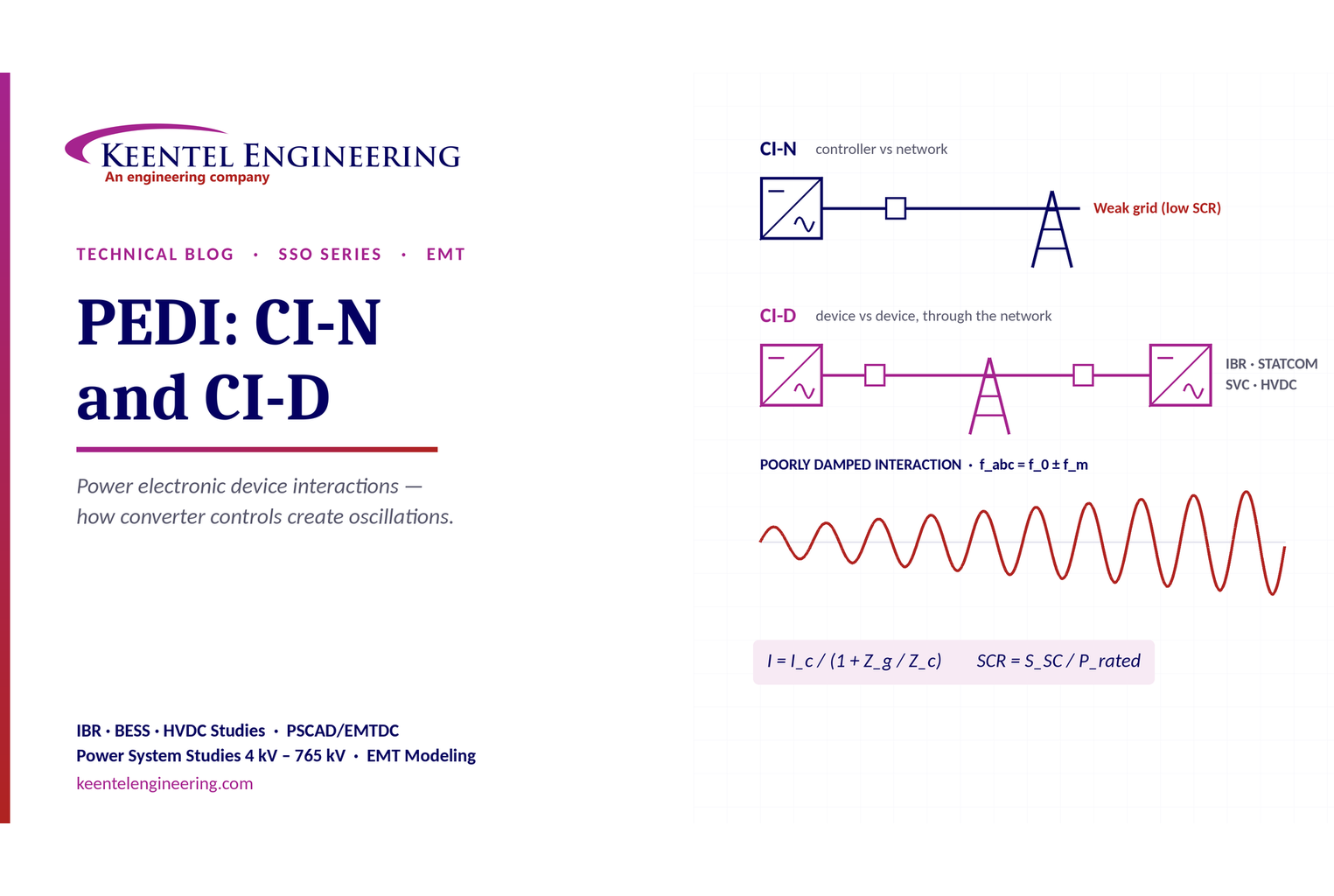
Learn power electronic device interactions (PEDI), including CI-N and CI-D, weak-grid stability, SCR, EMT studies, impedance analysis and mitigation for IBRs.
By SANDIP R PATEL
•
October 3, 2026
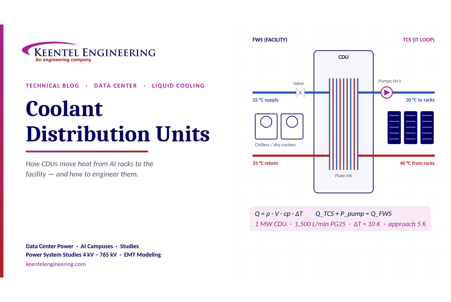
Learn how data center coolant distribution units (CDUs) work, including FWS and TCS loops, heat transfer, sizing, redundancy and liquid cooling for AI data centers.
By SANDIP R PATEL
•
October 3, 2026
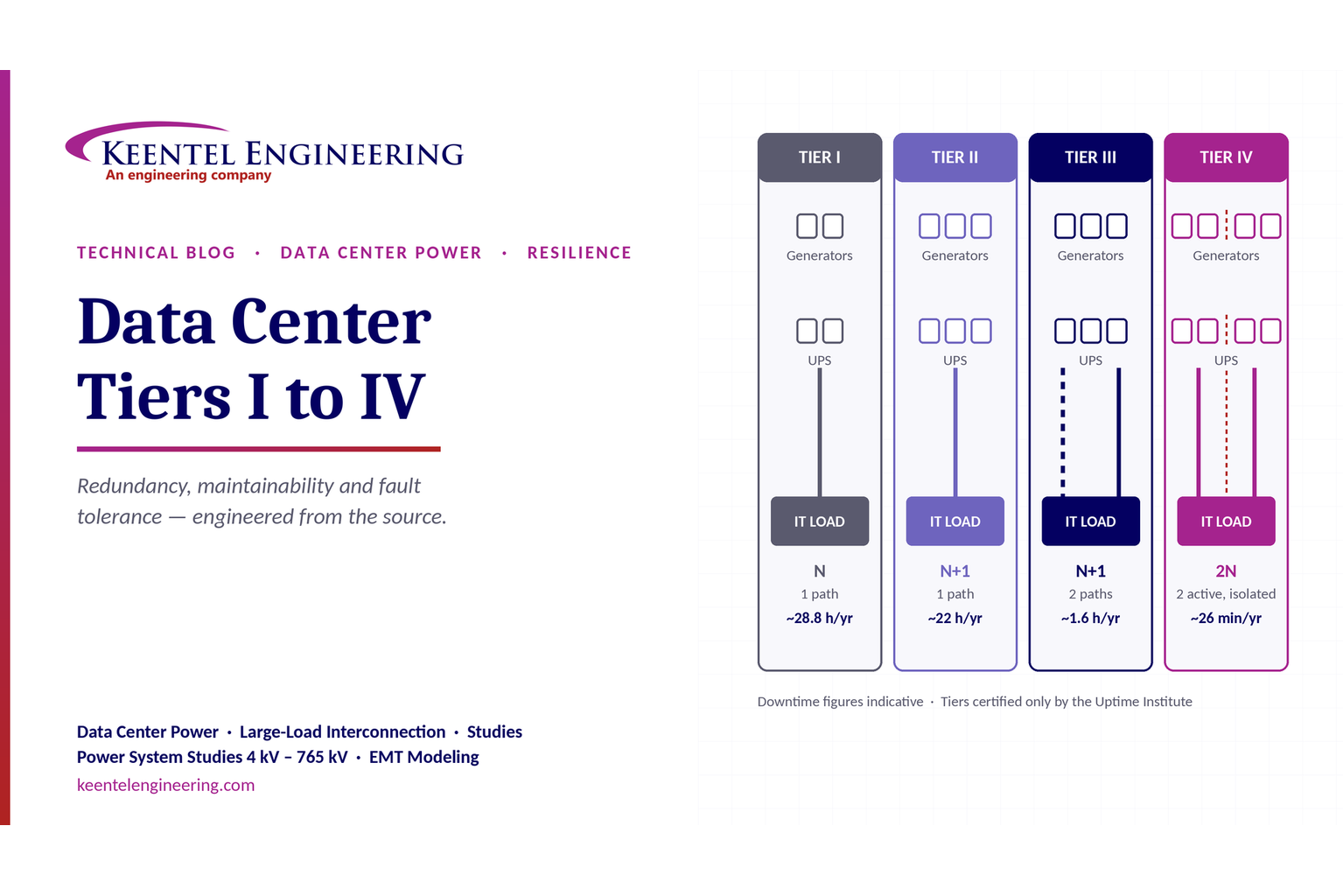
Compare Data Center Tiers I–IV, including redundancy, uptime, Tier III concurrent maintainability, Tier IV fault tolerance, UPS, generators and power design.

By SANDIP R PATEL
•
October 3, 2026
Learn how BESS supports grid stability through fast frequency response, voltage support, oscillation damping, black start, grid-forming controls and EMT studies.





