



A Coordinated Electric System Interconnection Review—the utility’s deep-dive on technical and cost impacts of your project.

Challenge: Frequent false tripping using conventional electromechanical relays
Solution: SEL-487E integration with multi-terminal differential protection and dynamic inrush restraint
Result: 90% reduction in false trips, saving over $250,000 in downtime

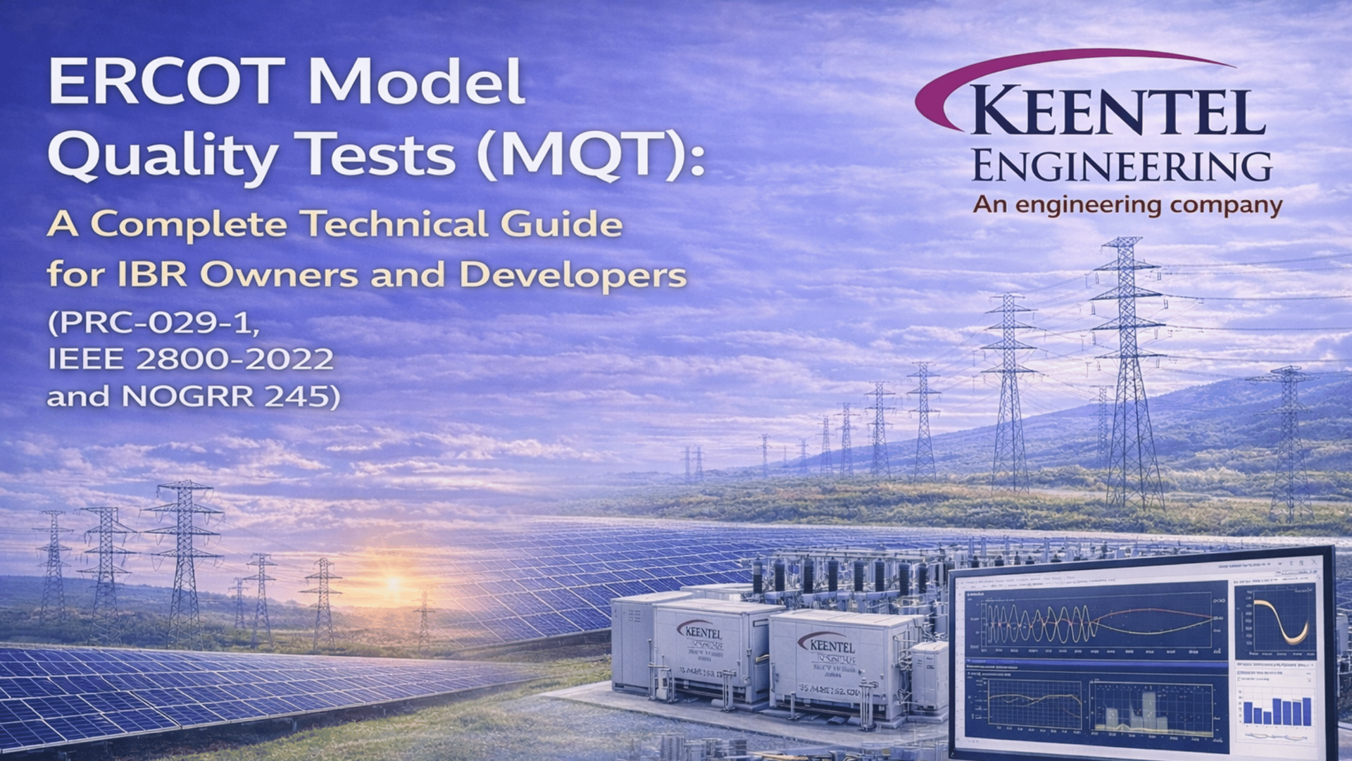
ERCOT Model Quality Tests (MQT): A Complete Technical Guide for IBR Owners and Developers. (PRC-029-1, IEEE 2800-2022, and NOGRR 245)

Solar panels in rows with a power plant featuring smokestacks emitting steam.
Calendar icon. D

December 26, 2025 | Blog

Introduction

As inverter-based resources (IBRs) continue to dominate new generation additions in ERCOT, the accuracy and reliability of dynamic models have become critical to system planning, operations, and reliability. ERCOT’s Model Quality Tests (MQT) defined in the Dynamics Working Group (DWG) Procedure Manual form the backbone of ERCOT’s model validation framework.

MQT ensures that resource models do not merely run, but respond correctly to realistic grid disturbances, providing confidence that planning and operational studies reflect actual system behavior. For Generator Owners, passing MQT is not optional it is a prerequisite for ERCOT acceptance of dynamic models and directly affects interconnection schedules and compliance obligations.


What Are ERCOT Model Quality Tests (MQT)?

ERCOT Model Quality Tests (MQT) are standardized dynamic simulation tests used to validate the performance of resource models submitted for ERCOT studies. These tests apply to:

  • Solar PV plants
  • Wind generation (Type 1–4)
  • Battery Energy Storage Systems (BESS)
  • Hybrid resources (solar + storage, wind + storage)
  • Synchronous generation
  • Dynamic reactive devices (STATCOM, SVC)

The purpose of MQT is to confirm that models:

  • Initialize properly,
  • Respond stably to voltage and frequency disturbances,
  • Exhibit correct ride-through behavior,
  • Provide appropriate reactive and frequency support,
  • Remain stable across required system strength (SCR) conditions.

Why ERCOT Uses a Controlled Testbench

MQT simulations are performed using a controlled testbench configuration:

Resource → Point of Interconnection (POI) → Infinite Bus

This framework:

  • Removes dependency on ERCOT system topology,
  • Ensures consistent and repeatable testing,
  • Allows fair comparison across different resources and technologies,
  • Prevents masking of model deficiencies by strong grid conditions.


In short, if a model performs correctly in the MQT testbench, ERCOT can trust it to behave appropriately in broader system studies.

See Keentel Engineering POI Services.


Core ERCOT MQT Simulation Tests

1. Flat Start Test

Validates:

  • Proper model initialization,
  • Steady-state convergence,
  • Absence of numerical instability.

Failure here typically indicates incorrect parameterization or model incompatibility.

2. Small Voltage Disturbance Test (±3%)

Validates:

  • Voltage control behavior,
  • Reactive current direction,
  • Damping and settling time.

This test is critical for verifying IEEE 2800 voltage support expectations.

3. Low Voltage Ride-Through (LVRT)

Validates:

  • Ride-through capability during voltage depressions,
  • Reactive current injection,
  • Recovery behavior without tripping.

LVRT tests directly support PRC-029-1 R1 and R2 and ERCOT NOG 2.9 requirements.

4. High Voltage Ride-Through (HVRT)

Validates:

  • Overvoltage tolerance,
  • Control stability,
  • Smooth recovery back to nominal conditions.

5. Small Frequency Disturbance Test (±0.3 Hz)

Validates:

  • Frequency response behavior,
  • Droop characteristics,
  • Proper response with and without headroom.

This test supports PRC-029-1 R3 and ERCOT NOG 2.6 requirements.

6. System Strength / SCR Sensitivity Testing

Required for IBRs to validate:

  • Stable operation at low SCR,
  • Control robustness,
  • Absence of oscillatory or unstable behavior.

This test is central to IEEE 2800-2022 performance expectations.

7. Phase Angle Jump Test (PSCAD-Only)

Required for inverter-based resources and performed in PSCAD (EMT).

Validates:

  • Control stability during sudden phase shifts,
  • PLL behavior,
  • Fast transient response not captured by RMS models.

This is the primary reason PSCAD is conditionally required under ERCOT rules.


Pass/Fail Criteria

ERCOT evaluates MQT results based on:

  • Correct reactive current direction and magnitude,
  • Stable damping and settling,
  • Successful ride-through and recovery,
  • Appropriate frequency response,
  • Stability at required SCR levels.

Passing MQT means ERCOT accepts the model.


Failing MQT may result in:

  • Model rejection,
  • Required retuning,
  • Re-submission delays,
  • Interconnection schedule impacts.

Relationship Between MQT, PRC-029-1, IEEE 2800, and NOGRR 245

MQT and PRC-029-1

  • LVRT/HVRT tests support R1 and R2.
  • Frequency disturbance tests support R3.
  • Post-event validation supports R4 and disturbance evidence.

MQT and IEEE 2800-2022

  • Voltage support (Section 5),
  • Frequency response (Section 7),
  • Stability and system strength (Section 9).

ERCOT MQT effectively operationalizes IEEE 2800 requirements.

MQT and NOGRR 245

  • Aligns with updated VRT/FRT requirements,
  • Supports performance maximization documentation,
  • Required after ride-through performance failures (NOG 2.13).

Why PSCAD Is Conditional, Not Universal

PSCAD is required only when EMT-level behavior must be evaluated, primarily for:

  • Phase angle jump tests,
  • Performance failure investigations,
  • Complex hybrid interactions.

Most MQT tests can be completed using PSS®E or TSAT, making PSCAD an as-needed, additional scope.


Best Practices for Generator Owners

  • Perform internal MQT checks before submission.
  • Coordinate closely with OEMs for accurate models.
  • Validate models against real disturbance data.
  • Address MQT failures early to avoid schedule risk.
  • Treat PSCAD as a contingency, not a baseline requirement.

Conclusion

ERCOT Model Quality Tests are not a formality they are a critical gatekeeper for model acceptance, system reliability, and regulatory compliance. Understanding MQT and its relationship to PRC-029-1, IEEE 2800-2022, and NOGRR 245 is essential for any Generator Owner operating in ERCOT.

Keentel Engineering supports clients through MQT preparation, model validation, PSCAD EMT analysis, and regulatory coordination, ensuring models are accepted the first time.


Frequently Asked Questions (FAQ)

  • 1. What is the purpose of ERCOT MQT?

    To verify that dynamic models accurately represent real-world grid behavior under disturbances.


  • 2. Is MQT required for all ERCOT resources?

    Yes, for any resource submitting dynamic models for ERCOT studies.


  • 3. Does passing MQT guarantee PRC-029-1 compliance?

    No, but it strongly supports Ride-through compliance evidence.


  • 4. Is PSCAD always required for MQT?

    No. PSCAD is required only for phase angle jump tests and specific EMT investigations.

  • 5. Which tools are typically used for MQT?

    PSS®E, TSAT, and PSCAD (when required).


  • 6. What happens if a model fails MQT?

    ERCOT may reject the model and require retuning and re-submission.


  • 7. How does MQT affect interconnection schedules?

    Failed MQT can delay studies and commercial operation timelines.


  • 8. Are hybrid plants treated differently in MQT?

    Yes. Control interactions between resources are closely evaluated.


  • 9. How does SCR affect MQT results?

    Low SCR can expose control instability not visible at strong grid conditions.


  • 10. Is MQT required after firmware updates?

    Often yes, especially if control behavior changes.


  • 11. Who is responsible for MQT submissions?

    The Resource Entity / Generator Owner.


  • 12. Can OEM models fail MQT?

    Yes. OEM models frequently require tuning for ERCOT conditions.


  • 13. What is the flat start test checking?

    Initialization stability and steady-state convergence.


  • 14. Why is phase angle jump tested in PSCAD?

    RMS models cannot capture fast electromagnetic transients.


  • 15. Does MQT replace event-based model validation?

    No. Both are required when applicable.


  • 16. How does MQT support IEEE 2800 compliance?

    It validates voltage, frequency, and stability performance.


  • 17. Are MQT plots reviewed manually by ERCOT?

    Yes, by ERCOT and DWG reviewers.


  • 18. Can Keentel Engineering support MQT preparation?

    Yes—full MQT, PSCAD, and compliance support.


  • 19. Is MQT required for BESS-only plants?

    Yes, if they provide dynamic grid services.


  • 20. Can MQT results be reused?

    Only if models and configurations remain unchanged.


  • 21. Does NOGRR 245 increase MQT scrutiny?

    Yes, especially for Ride-through performance.


  • 22. What data is needed for MQT?

    Dynamic models, control settings, and plant configuration.


  • 23. How long does MQT typically take?

    Several weeks, depending on complexity and revisions.


  • 24. Can MQT trigger PSCAD scope later?

    Yes, if EMT behavior needs investigation.


  • 25. What is the biggest MQT failure risk?

    Inaccurate or untuned inverter control parameters


A smiling man with glasses and a beard wearing a blue blazer stands in front of server racks in a data center.

About the Author:

Sandip "Sonny" R. Patel, P.E.

IEEE Senior Member · Founder & CEO, Keentel Engineering

In 1995, Sonny Patel earned his Electrical Engineering degree from the University of Illinois. But degrees don't build legacies — action does.

For three decades, he has worked the power industry from every side of the table: 16 years as a utility engineer at Exelon/Commonwealth Edison; generation leadership across hydroelectric, industrial steam turbine, and a 9 GW renewable fleet; NERC Regional Entity Senior Compliance Engineer and Audit Team Lead, auditing some of the nation's largest utilities; and testing and commissioning lead on equipment up to 765 kV — the very top of the North American grid.Utility. Generator. Regulator. Consultant. Few engineers have seen all four seats. Fewer still have sat in them.

His experience spans nuclear, hydro, conventional generation, renewables, oil and gas, mining — and today's data centers, where he is authoring a three-book series on data center design. He is a Licensed Professional Engineer in six states and a Licensed Electrical Contractor in Florida (Unlimited EC) — he doesn't just design the work; he's qualified to stand behind its execution.Today, as Founder and CEO of Keentel Engineering, Sonny leads a nationwide team of engineers delivering substation design, power system studies, NERC compliance, and commissioning — done right, coast to coast.Three decades. Every side of the table. One standard: accountable engineering.

Four workers in safety vests and helmets stand with arms crossed near wind turbines.

Let's Discuss Your Project

Let's book a call to discuss your electrical engineering project that we can help you with.

Man in a blazer and open shirt, looking at the camera, against a blurred background.

About the Author:

Sandip "Sonny" R. Patel, P.E.

IEEE Senior Member · Founder & CEO, Keentel Engineering

In 1995, Sonny Patel earned his Electrical Engineering degree from the University of Illinois. But degrees don't build legacies — action does.

For three decades, he has worked the power industry from every side of the table: 16 years as a utility engineer at Exelon/Commonwealth Edison; generation leadership across hydroelectric, industrial steam turbine, and a 9 GW renewable fleet; NERC Regional Entity Senior Compliance Engineer and Audit Team Lead, auditing some of the nation's largest utilities; and testing and commissioning lead on equipment up to 765 kV — the very top of the North American grid.

Utility. Generator. Regulator. Consultant. Few engineers have seen all four seats. Fewer still have sat in them.

His experience spans nuclear, hydro, conventional generation, renewables, oil and gas, mining — and today's data centers, where he is authoring a three-book series on data center design. He is a Licensed Professional Engineer in six states and a Licensed Electrical Contractor in Florida (Unlimited EC) — he doesn't just design the work; he's qualified to stand behind its execution.

Today, as Founder and CEO of Keentel Engineering, Sonny leads a nationwide team of engineers delivering substation design, power system studies, NERC compliance, and commissioning — done right, coast to coast.Three decades. Every side of the table. One standard: accountable engineering.

Leave a Comment

Related Posts

PRC-028 PRC-029 and PRC-030 NERC IBR compliance guide
By SANDIP R PATEL • October 3, 2026
Engineering guide to PRC-028 disturbance recording, PRC-029 ride-through and PRC-030 event detection for inverter-based resources.

Keentel Engineering graphic showing damped and undamped subsynchronous oscillations.
By SANDIP R PATEL • October 3, 2026
A practical guide to SSO classification, SSR, PEDI, Wind-SSCI, EMT analysis, mitigation and protection based on CIGRE TB 909.

PV String I-V Curve Testing for Solar Performance Loss
By SANDIP R PATEL • October 3, 2026
Learn how PV string I-V curve testing identifies hidden solar performance losses, including soiling, shading, mismatch, degradation, and wiring faults.

Active harmonic filter reducing VFD current harmonics and grid THDi.
By SANDIP R PATEL • October 3, 2026
Learn how active harmonic filters work, how to size AHF systems, reduce VFD harmonics, calculate losses, and meet IEEE 519 TDD limits at the PCC.
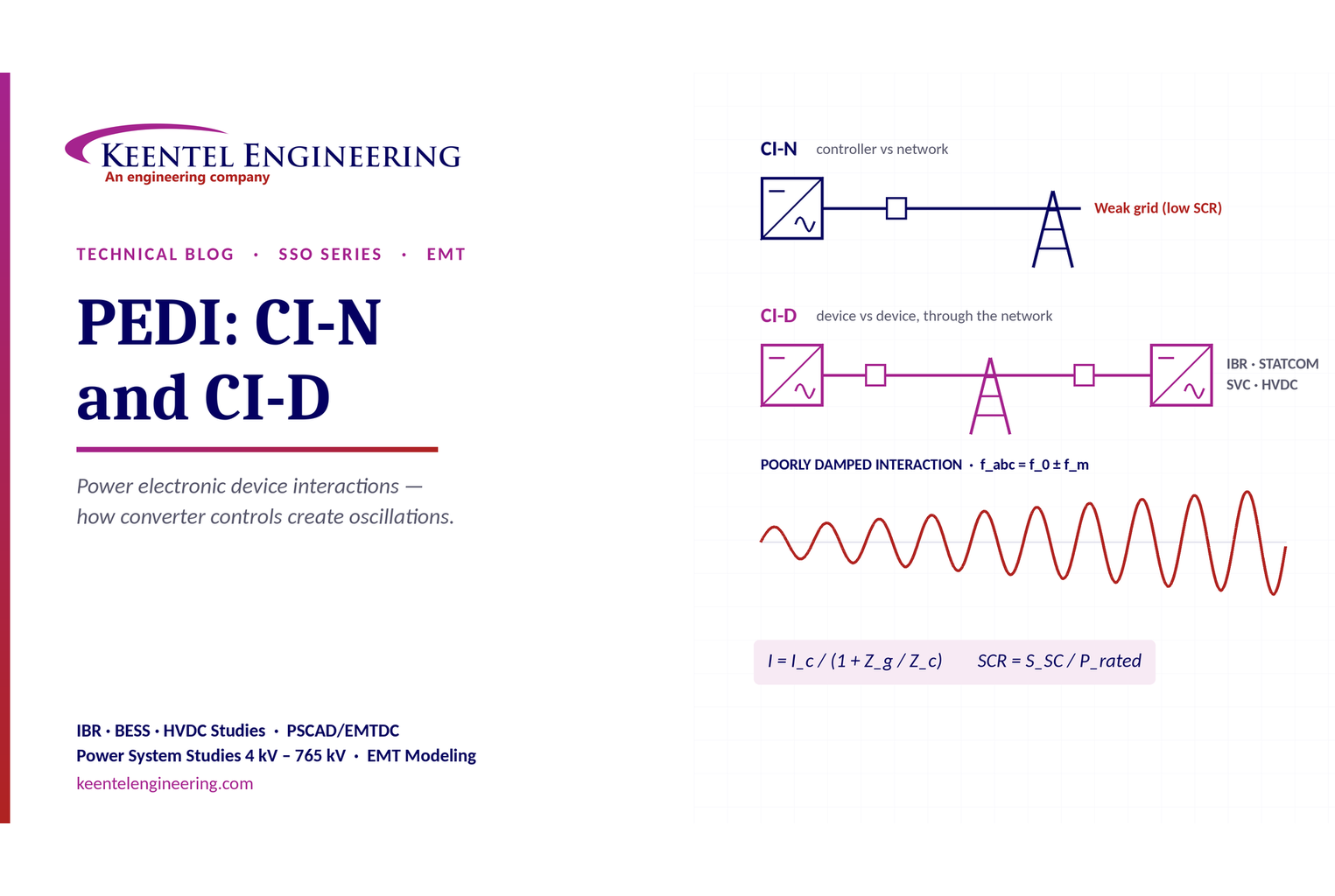
PEDI CI-N and CI-D power system interaction diagram
By SANDIP R PATEL • October 3, 2026
Learn power electronic device interactions (PEDI), including CI-N and CI-D, weak-grid stability, SCR, EMT studies, impedance analysis and mitigation for IBRs.
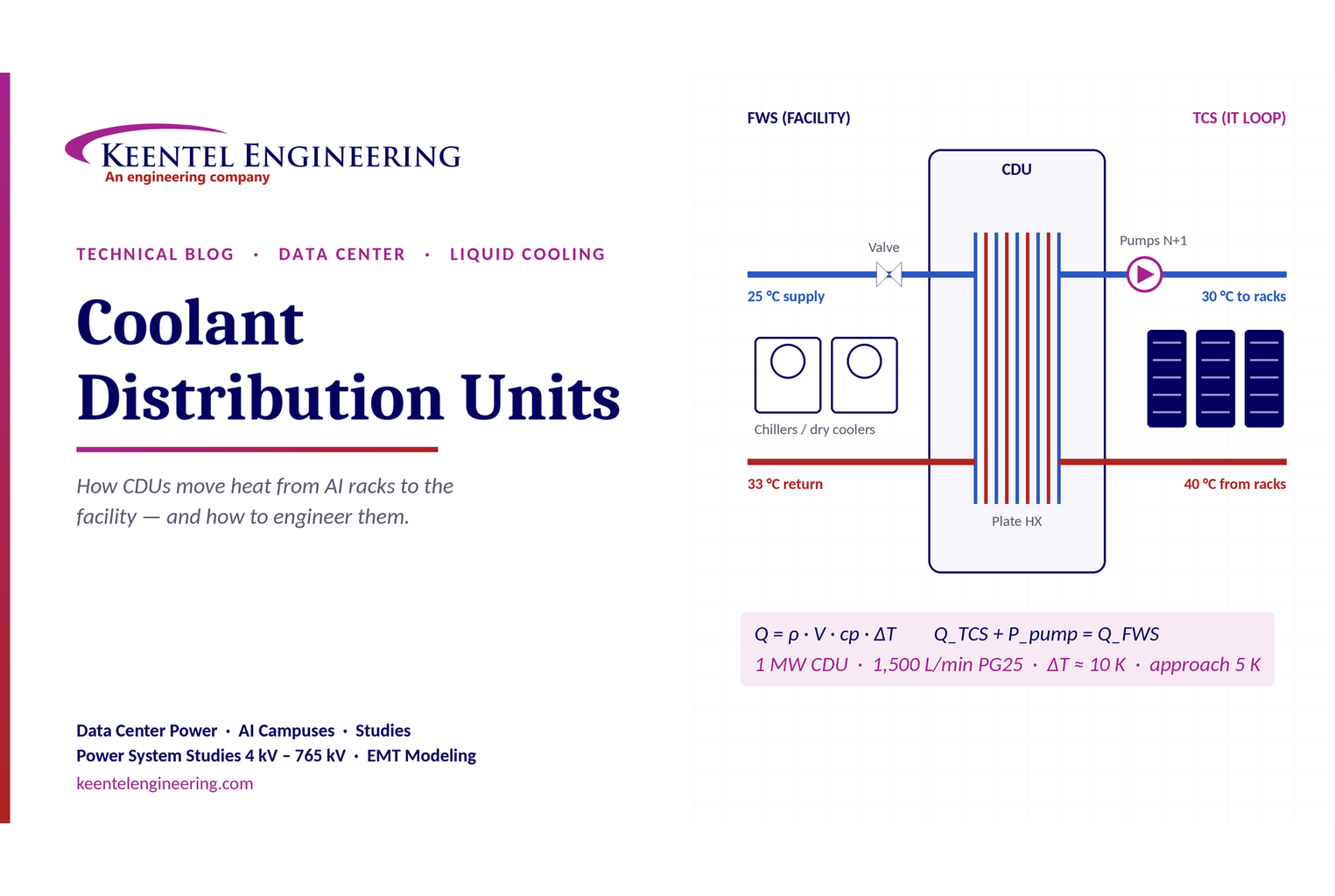
Coolant distribution unit for data center cooling
By SANDIP R PATEL • October 3, 2026
Learn how data center coolant distribution units (CDUs) work, including FWS and TCS loops, heat transfer, sizing, redundancy and liquid cooling for AI data centers.
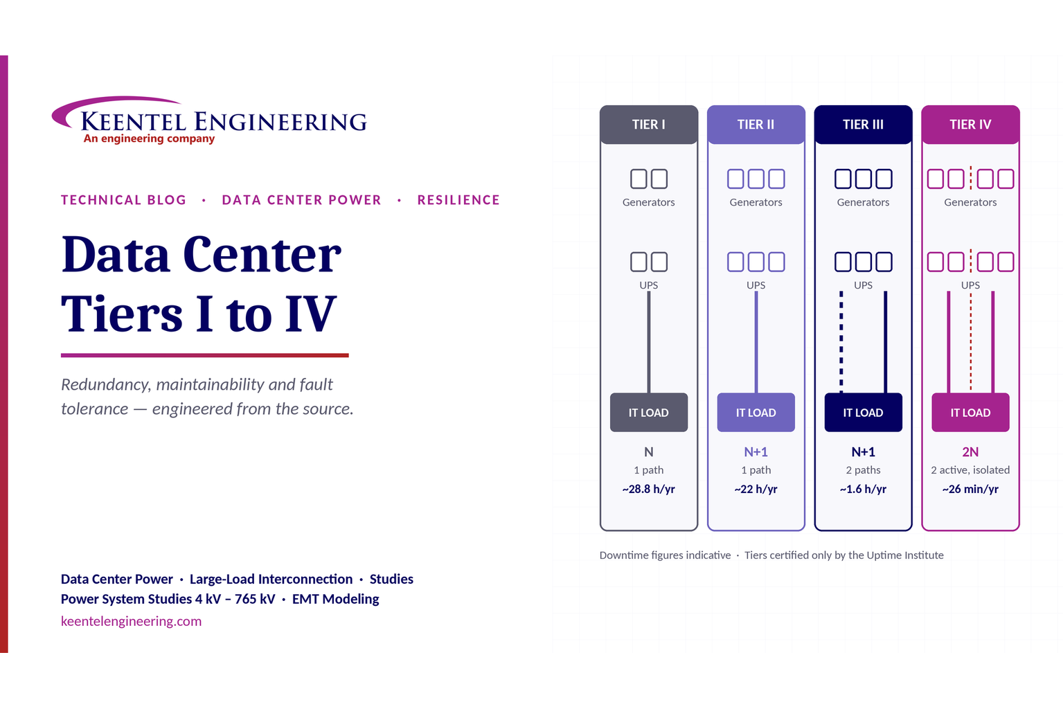
Data Center Tiers I to IV: An Electrical Engineer's Guide to Redundancy, Maintainability and Fault T
By SANDIP R PATEL • October 3, 2026
Compare Data Center Tiers I–IV, including redundancy, uptime, Tier III concurrent maintainability, Tier IV fault tolerance, UPS, generators and power design.

BESS grid stability with frequency response and POI interconnection.
By SANDIP R PATEL • October 3, 2026
Learn how BESS supports grid stability through fast frequency response, voltage support, oscillation damping, black start, grid-forming controls and EMT studies.
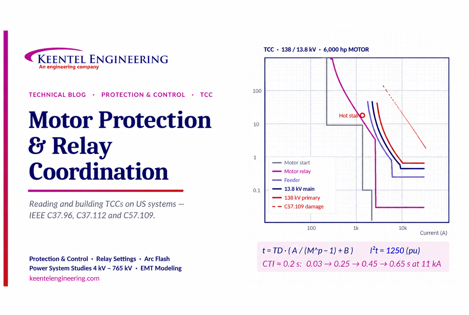
Motor Protection & Relay Coordination TCC Guide
By SANDIP R PATEL • October 3, 2026
Learn motor protection and relay coordination using TCC curves, IEEE standards, transformer damage limits, CTI settings and a 138/13.8 kV example.





