
A Coordinated Electric System Interconnection Review—the utility’s deep-dive on technical and cost impacts of your project.
Challenge: Frequent false tripping using conventional electromechanical relays
Solution: SEL-487E integration with multi-terminal differential protection and dynamic inrush restraint
Result: 90% reduction in false trips, saving over $250,000 in downtime
The three operating regions you have to design to
| Device | Output vs voltage | Response | Best suited to | Main limitations |
|---|---|---|---|---|
| Mechanically switched capacitor or reactor | Proportional to voltage squared | Seconds; discrete steps; limited switching operations per day | Steady-state reactive supply, voltage profile, loss reduction | No dynamic capability; step voltage change on switching; capability collapses when most needed |
| Static var compensator | Capacitive branches proportional to voltage squared | A few cycles; continuously controllable | Continuous control where cost matters and deep voltage support is not the driver | Square-law capability loss; harmonic filters are part of the plant and interact with the network |
| STATCOM | Approximately proportional to voltage — constant current capability | One to two cycles closed loop; converter response faster still | Voltage stability margin, weak interconnections, fast disturbance recovery, flicker and unbalance compensation | Higher capital cost; converter losses; adds a converter and its control dynamics to the network |
| Synchronous condenser | Governed by machine capability and excitation | Excitation response in the hundreds of milliseconds; inherent inertial response instantaneous | System strength and inertia, short-circuit contribution, black start support | Rotating plant with maintenance and losses; slower controlled response than a converter |
| STATCOM with energy storage | Reactive as a STATCOM, plus real power within the storage rating | As STATCOM for reactive; real power limited by storage | Where a real power deficiency is part of the problem | Cost and complexity of the storage; different failure and maintenance profile |
| Stage | Keentel scope | Outcome |
|---|---|---|
| Screening | Series-compensation proximity, radial contingency review, UIF and short-circuit ratio screening, frequency scans | Early identification of which SSO types apply |
| Detailed studies | PSCAD/EMTDC EMT studies with vendor real-code models, impedance-based and frequency-scan analysis | Clear evidence of stability margins or risk |
| Model quality | EMT model review, benchmarking against positive-sequence models, model acceptance support | Models that system operators accept |
| Mitigation | Control retuning recommendations with vendors, SSDC and bypass logic requirements, protection and monitoring specifications | Practical, coordinated solutions |
| Interconnection support | SSR and SSO study reports for ISO and utility requirements, response to reviewer comments | Fewer delays in the interconnection process |
Data Center Tiers I to IV: An Electrical Engineer's Guide to Redundancy, Maintainability and Fault Tolerance
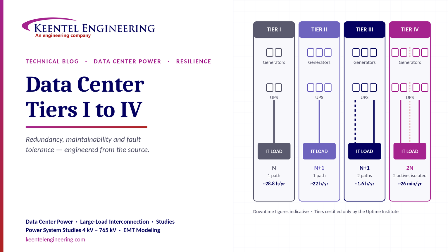
October 03, 2026 | Blog
Part A — Data Center Tiers at a Glance
Data center Tiers describe how much of the site infrastructure can be maintained, or can fail, without interrupting the IT load. Higher Tiers buy more availability with more redundancy, more distribution paths and more cost. The Tier classification system was created by the Uptime Institute, which is the only organisation that certifies facilities against it.
The four Tiers
| Feature | Tier I | Tier II | Tier III | Tier IV |
|---|---|---|---|---|
| Objective | Basic capacity | Redundant capacity components | Concurrently maintainable | Fault tolerant |
| Power and cooling capacity | N (no redundancy) | N+1 components | N+1 components | Independent systems (commonly 2N or 2N+1) |
| Distribution paths | Single | Single | Multiple (one active, one alternate) | Multiple, simultaneously active, physically isolated |
| Maintenance | Requires shutdown | Path maintenance causes downtime | Any component or path can be maintained without impacting IT | Any component or path can be maintained without impacting IT |
| Response to a single failure | Outage likely | Component failures covered; path failure causes outage | Planned work protected; some unplanned failures can still cause an outage | A single failure or path loss does not disrupt IT operations |
| Continuous cooling | Not required | Not required | Not required | Required |
| Indicative availability | ~99.671% | ~99.741% | ~99.982% | ~99.995% |
| Indicative downtime per year | ~28.8 h | ~22 h | ~1.6 h | ~26 min |
| Typical use | Small business, test environments | SMBs, regional offices | Enterprise, banking, healthcare, cloud | Hyperscale, finance, government, mission-critical |
The key insight
- The jump from Tier II to Tier III is about maintainability: the second distribution path.
- The jump from Tier III to Tier IV is about fault tolerance: isolation and compartmentalisation.
Two things to remember
- Availability percentages are indicative. Tiers are defined by topology and performance objectives, not by uptime statistics. The current Uptime Institute Tier Standard does not specify availability percentages.
- Only the Uptime Institute certifies Tiers, for Design Documents, Constructed Facility and Operational Sustainability. Do not confuse a Tier with the "Rated" levels of ANSI/TIA-942 or the Classes of ANSI/BICSI 002.
The right Tier balances uptime, redundancy and business requirements. It is not just about infrastructure; it is about keeping the business running.
Part B — Data Center Tiers I to IV: An Electrical Engineer's Guide to Redundancy, Maintainability and Fault Tolerance
What each Tier really requires from the power, cooling and fuel systems, how to calculate what redundancy buys, and how to choose and deliver the right Tier for an enterprise, colocation or hyperscale facility.
Why Tiers matter more than ever
Data center construction is growing fast, driven by cloud and AI workloads. At the same time, the cost of downtime has risen sharply, and owners, tenants, lenders and insurers all want a common language for resilience. The Tier classification system gives them one. It describes the site infrastructure, not the IT systems, in terms of two questions:
- Can every piece of equipment be taken out of service for maintenance without affecting the IT load? That is concurrent maintainability, the heart of Tier III.
- Can any single failure or event happen without affecting the IT load? That is fault tolerance, the heart of Tier IV.
Everything else, from UPS module counts to fuel piping, follows from those two questions.
Who defines what: Uptime, TIA and BICSI
Three frameworks are commonly confused:
| Framework | Levels | Who assesses | Scope |
|---|---|---|---|
| Uptime Institute Tier Standard: Topology and Operational Sustainability | Tier I, II, III, IV | Uptime Institute only (Tier Certification of Design Documents, Constructed Facility, Operational Sustainability) | Site infrastructure topology and operations |
| ANSI/TIA-942-C (published May 2024) | Rated-1, Rated-2, Rated-3, Rated-4 |
Self-assessment or third-party conformity bodies | Telecommunications infrastructure plus architectural, electrical, mechanical and other site systems |
| ANSI/BICSI 002 | Classes F0 to F4 | Design guidance; no single certifying body | Data center design and implementation best practices |
The levels line up conceptually: Rated-3 and Class F3 are broadly comparable to Tier III objectives. But they are different documents with different requirements and assessment methods. A facility should be described as "Tier III Certified" only when Uptime Institute has certified it. Otherwise, "designed to Tier III objectives" or "TIA-942 Rated-3" is accurate.
The source of power: why the generator, not the utility
The Tier Standard treats on-site engine generators as the facility's reliable power source. Utility power is valuable and economical, but it is outside the owner's control, so it is not counted towards the Tier objective.
Two consequences matter for electrical design:
- Generator ratings. For Tier III and IV, Uptime Institute accepts only continuous ratings, derated prime ratings, or standby ratings with no runtime limitation. A standby-rated generator with limited annual run hours does not qualify on its own.
- Fuel. The Tier Standard sets a minimum of 12 hours of on-site fuel storage at the design load as a starting point for all Tiers. For Tier III and IV, the fuel supply path, including pumps, day tanks and piping, must itself be concurrently maintainable or fault tolerant.
In the United States, generator systems also fall under the National Electrical Code (Articles 700, 701 and 702 depending on the load classification) and NFPA 110 for emergency and standby power systems. Tier objectives sit on top of, not instead of, those code requirements.
Understanding N, N+1, 2N and 2N+1
Redundancy is described relative to N, the capacity needed to carry the design load.
| Notation | Meaning | Example for a 2 MW IT load with 500 kW UPS modules |
|---|---|---|
| N | Exactly enough capacity | 4 modules, one system |
| N+1 | One spare component | 5 modules, one system |
| 2N | Two complete, independent systems, each able to carry the load | Two systems of 4 modules each (A and B) |
| 2N+1 | Two independent systems, each with a spare | Two systems of 5 modules each |
| Distributed redundant (for example 4-to-make-3) | Several systems, each loaded below its rating, so any one can fail | Four systems of 667 kW usable, each loaded to about 500 kW |
N+1 protects against the failure of a component. It does not protect against the failure of the path, such as a switchboard, a bus, a cable or a breaker, that all components share. That is why Tier II remains vulnerable even with redundant UPS modules and generators.
Tier I: Basic capacity
A Tier I site has dedicated space for IT systems, a UPS to ride through sags and short interruptions, dedicated cooling that runs outside office hours, and an engine generator for extended outages. There is no redundancy and a single distribution path.
Electrical implications. A single utility service and generator feed one automatic transfer switch, one UPS system and one distribution path. Any maintenance on the switchgear, UPS or distribution requires an IT shutdown, as does any failure in them.
Where it fits. Small server rooms, test and development environments, and businesses that can schedule downtime.
Tier II: Redundant capacity components
Tier II adds redundant capacity components: N+1 UPS modules, generators, chillers, pumps and cooling units. Distribution remains a single path.
Electrical implications. A failed UPS module or generator no longer causes an outage, and individual components can be serviced while the others carry the load. But the switchgear, UPS output board, distribution panels and cabling form one path. Maintaining any of them still means shutting down the IT load.
Where it fits. Small and medium businesses and regional offices where some planned downtime is acceptable.
Tier III: Concurrently maintainable
Tier III requires that every capacity component and every element of the distribution path can be removed from service on a planned basis without affecting the IT load. This includes items engineers often forget: switchgear buses, breakers, transfer switches, control power, fuel pumps and piping, chilled-water valves and pipe sections.
Electrical implications.
- Two distribution paths to the IT load, one active and one alternate. In practice most designs make both paths active, using dual-corded IT equipment fed from an A and a B source.
- Concurrently maintainable switchgear. Main-tie-main or double-ended arrangements, isolation points on both sides of every component, and the ability to transfer load without interruption or with closed-transition transfers.
- Single-corded IT loads need a point-of-use transfer switch or rack automatic transfer switch, so they can be fed from either path.
- Control and monitoring power must also be maintainable. A single DC control bus or a single PLC for generator paralleling defeats the topology.
- Mechanical systems need the same treatment: N+1 chillers and cooling units, plus valving and piping arranged so any section can be isolated.
The limitation. Concurrent maintainability protects planned work. While one path is out of service for maintenance, an unplanned failure on the remaining path can still cause an outage. Tier III also does not require compartmentalisation, so a fire or other event that affects both paths at one point can disrupt IT.
Where it fits. The most common choice for enterprise, banking, healthcare and colocation facilities, because it removes the large majority of downtime caused by maintenance at a moderate cost premium.
Tier IV: Fault tolerant
Tier IV requires that any single failure of a capacity component, distribution element or event, such as a fire, leak or explosion in one location, does not affect the IT load. It builds on Tier III with three additional requirements:
- Fault tolerance. Multiple independent systems, commonly 2N UPS and distribution, so the loss of any one system leaves enough capacity on the other.
- Compartmentalisation. Redundant systems and their paths are physically separated, in separate rooms, fire-rated enclosures or routes, so that one event cannot reach both.
- Continuous cooling. Cooling must continue without interruption during a utility failure and generator start, because high-density IT equipment can overheat in the tens of seconds before chillers restart. This usually means UPS-backed pumps and air handlers, thermal storage tanks, or both.
Electrical implications. Fault-tolerant generator paralleling, with no single bus or controller whose failure can disable the plant; physically separated A and B switchgear, UPS and battery rooms; separate cable routes; and automatic response to failures, so that recovery does not depend on operator action.
Where it fits. Hyperscale, financial trading, government and mission-critical applications where even a single outage carries very high cost.
What the availability numbers really mean
The often-quoted percentages come from early Uptime Institute papers that summarised the observed performance of sites in each category. They are useful for intuition but are not part of the current Tier Standard, which defines Tiers by topology and performance objectives.
Annual downtime follows directly from availability:

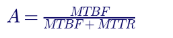
Engineers who need numbers for a specific design should calculate them. Availability of a component is:
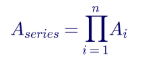
For components in series, every one must work:
For independent redundant paths, only one must work:
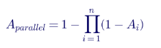
Worked example. Suppose a single distribution path has five components in series, each with availability 0.9999. The path availability is 0.9999⁵ ≈ 0.9995, about 4.4 hours of downtime a year. Two fully independent such paths in parallel give 1 − (0.0005)² ≈ 0.99999975, a few seconds a year. Real systems never reach that ideal, because of common-cause failures, shared controls and human error. That is exactly why Tier IV adds compartmentalisation and why operations matter as much as topology. IEEE Std 3006.7 and the legacy IEEE Std 493 (Gold Book) give data and methods for formal reliability studies.
Electrical architecture choices that deliver each Tier
| Element | Tier I | Tier II | Tier III | Tier IV |
|---|---|---|---|---|
| Utility service | Single | Single | Single or dual (not counted towards the Tier) | Single or dual (not counted towards the Tier) |
| Engine generators | N | N+1 | N+1, continuous-rated, concurrently maintainable paralleling | N+1 or 2N, fault-tolerant paralleling and controls |
| Medium-voltage and low-voltage switchgear | Single bus | Single bus | Main-tie-main or dual buses; isolation on both sides of every component | Physically separated A and B switchgear |
| UPS | N | N+1 | N+1 with dual output paths, or 2N | 2N, 2N+1 or distributed redundant, compartmentalised |
| Distribution to IT | Single path | Single path | A and B paths; rack ATS for single-corded loads | A and B paths, physically separated |
| Fuel | 12 h minimum | 12 h minimum, redundant pumps | 12 h minimum, concurrently maintainable supply | 12 h minimum, fault-tolerant supply |
| Cooling | N | N+1 | N+1 with maintainable piping and valves | Fault tolerant, compartmentalised, continuous cooling |
UPS topology options for Tier III and IV
- Isolated redundant (catcher) and block redundant designs use a shared reserve system that picks up any failed module or system through static transfer switches. They save capital cost but add switching complexity.
- 2N is the simplest fault-tolerant design. Each side is loaded below 50% in normal operation, which reduces efficiency unless high-efficiency modes are used.
- Distributed redundant designs, such as 4-to-make-3, load each system to about 75% of its rating, improving utilisation. They require careful load balancing so that losing any one system never overloads the others.
Arc flash and maintenance safety
Concurrent maintainability lets technicians work on de-energised equipment while the IT load continues on the other path. Designs should therefore provide visible isolation points, interlocks, maintenance-mode protective settings and arc-flash mitigation, coordinated through protective device and arc-flash studies to IEEE Std 1584 and NFPA 70E.
Commissioning and operations: where Tiers are proven
A design delivers a Tier only if it is built and operated as intended. Commissioning normally progresses through five levels, from factory witness testing (Level 1) to integrated systems testing (Level 5), where the whole facility is subjected to utility failures, component failures and maintenance scenarios under load banks. The Tier Certification of Constructed Facility relies on demonstrating the topology in exactly these scenarios.
After handover, the Uptime Institute's Operational Sustainability criteria cover staffing, maintenance, training, procedures and planning. Industry outage surveys repeatedly find that human error and process failures cause a large share of significant outages, so operations deserve as much attention as topology.
AI and high-density data centers: new pressures on Tier design
- Rack densities of tens to over 100 kW move cooling towards direct-to-chip liquid cooling. Continuous cooling then means keeping coolant distribution units and pumps on UPS power, not just air handlers.
- Rapid load swings from AI training workloads can stress UPS, generators and the utility interconnection. Generator transient response and UPS behaviour should be studied with realistic load profiles.
- Large utility interconnections at 69 kV to 345 kV bring new requirements from utilities and system operators. Dual utility feeds improve economics and reliability, but the Tier objective still rests on the on-site plant.
- Footprint and capital pressure push hyperscale designs towards distributed redundant and catcher architectures that achieve fault tolerance with less idle capacity.
Choosing the right Tier
- Quantify the cost of downtime per hour and per event, including reputational and contractual penalties.
- Define the maintenance model. If the business cannot accept planned shutdowns, Tier III is the minimum.
- Assess single-event risk. If one failure or fire must never interrupt service, Tier IV or an equivalent fault-tolerant design is needed.
- Consider IT-level resilience. Workloads replicated across several sites can sometimes justify a lower site Tier at each location.
- Plan for growth. Choose an architecture that can be expanded without breaking concurrent maintainability.
- Decide on certification early. Certification of Design Documents should happen before construction documents are finished, when changes are still cheap.
How Keentel Engineering helps
Keentel Engineering delivers data center power engineering, from utility interconnection and substation design to medium- and low-voltage distribution, with
power system studies from 4 kV to 765 kV. Keentel designs to the Tier objective the owner selects and supports the owner through the Uptime Institute certification process; certification itself is issued only by the Uptime Institute.
| Stage | Keentel scope | Outcome |
|---|---|---|
| Planning and Tier strategy | Tier objective selection support, architecture options (2N, N+1, distributed redundant, catcher), reliability and life-cycle cost comparison | The right Tier at the right cost |
| Utility interconnection | Large-load interconnection studies, dual-feed and on-site substation design from 69 kV to 345 kV and above | Power delivered on time and to utility requirements |
| Electrical design | Medium- and low-voltage switchgear, generator paralleling, UPS and distribution design, grounding and protection | A topology that meets the Tier objective in every operating mode |
| Studies | Short-circuit, protective device coordination, arc-flash, load flow, motor and transformer energisation, harmonic and transient studies | Safe, selective and stable systems |
| Concurrent maintainability and fault tolerance reviews | Component-by-component maintenance and failure-scenario reviews of drawings | Gaps found on paper, not during operation |
| Commissioning support | Level 1 to Level 5 test planning and witnessing support, integrated systems test scenarios | Evidence that the facility performs as designed |
Planning a new data center, an expansion or a Tier upgrade? Talk to Keentel Engineering at (813) 389-7871, contact@keentelengineering.com, or book a 15-minute scoping call at calendly.com/keentel-engineering/15min.
Part C — Case Studies
The following are illustrative scenarios based on conditions typical of enterprise, colocation and hyperscale data centers. They show how Keentel Engineering approaches data center power design; site details are generalised and figures are rounded.
Case Study 1 — Colocation design review: closing hidden Tier III gaps
Situation. A developer is designing a 12 MW colocation facility to Tier III objectives and plans to pursue Tier Certification of Design Documents. The 90% electrical drawings show N+1 generators, N+1 UPS and A/B distribution to every rack.
Analysis. A component-by-component concurrent maintainability review walks through every switchgear bus, breaker, transfer switch, control system and fuel component. It finds four gaps: a single generator paralleling control PLC, a single fuel supply header to all day tanks, a shared DC control power panel for both A and B switchgear, and a mechanical plant with a single chilled-water header valve that cannot be isolated.
Engineered solution. Redundant paralleling controllers with independent control power; a looped fuel header with isolation valves so any section can be maintained; separate A and B DC control systems; and a valved, looped chilled-water header. Each change is documented against the maintenance scenario it resolves.
Outcome. The design closes the gaps before construction documents are issued, when the changes cost a fraction of what they would after construction.
Case Study 2 — Enterprise data center upgraded to concurrent maintainability while live
Situation. A regional bank's 1.5 MW data center was built to Tier II: N+1 UPS and generators on a single switchboard and single distribution path. Every switchgear maintenance outage requires weekend shutdowns that the business no longer accepts.
Analysis. A load and topology study shows enough space and capacity to add a second UPS output path and a second distribution path, and that most IT equipment is already dual-corded. About 8% of loads are single-corded legacy devices.
Engineered solution. A phased upgrade adds a second UPS output switchboard and B-side distribution, rack transfer switches for single-corded loads, and a main-tie-main arrangement for the low-voltage switchgear. Each cutover is planned with a detailed method of procedure, temporary feeds, protective device setting changes and arc-flash review, so the IT load never loses both sources.
Outcome. The facility moves from scheduled shutdowns to concurrently maintainable operation without a planned IT outage during the project.
Case Study 3 — AI campus: choosing the redundancy architecture
Situation. A developer plans a 100 MW AI campus served from a new 138 kV substation with two utility lines. The owner wants fault tolerance at the lowest capital cost and the smallest electrical footprint.
Analysis. Keentel compares 2N, distributed redundant (4-to-make-3) and catcher architectures for each 10 MW data hall. The comparison covers UPS and generator count, utilisation, efficiency, failure scenarios, compartmentalisation and the behaviour of the plant under rapid AI training load swings. Utility interconnection studies confirm the substation design and the facility's ride-through requirements.
Engineered solution. A distributed redundant architecture with physically separated systems and fault-tolerant generator paralleling, combined with UPS-backed coolant distribution units and pumps for continuous liquid cooling. Generator and UPS selections are checked against measured AI load profiles.
Outcome. The selected architecture meets the fault-tolerance objective with materially fewer UPS modules and generators than 2N, freeing space and capital for IT capacity.
Part D — Technical FAQ: Data Center Tiers
They are a four-level classification of data center site infrastructure, created by the Uptime Institute. Each Tier sets a performance objective: Tier I basic capacity, Tier II redundant capacity components, Tier III concurrent maintainability and Tier IV fault tolerance. Higher Tiers include all the requirements of lower ones.
Only the Uptime Institute. It offers Tier Certification of Design Documents, Tier Certification of Constructed Facility and Operational Sustainability certification. Engineers and contractors design and build to Tier objectives, but they cannot certify a Tier.
ANSI/TIA-942-C, published in 2024, defines Rated-1 to Rated-4 across telecommunications, architectural, electrical and mechanical systems. Its levels are conceptually similar to Tiers but are a separate standard with different requirements and assessment methods. A facility should not be called "Tier III" because it meets TIA-942 Rated-3.
ANSI/BICSI 002 uses Classes F0 to F4 to describe data center design practice and resilience. It is a design best-practice standard rather than a certification scheme. Many designs reference all three frameworks.
No. Figures such as 99.671% for Tier I and 99.995% for Tier IV come from early Uptime Institute papers summarising observed site performance. The current Tier Standard defines Tiers by topology and performance objectives, not by uptime statistics, so the percentages should be treated as indicative.
N is the capacity needed to carry the design load; N+1 adds one more component than needed. With five 500 kW UPS modules serving a 2 MW load, any one module can fail or be maintained while the other four carry the load.
Because its components share one distribution path. A failure or maintenance on the shared switchboard, UPS output bus, distribution panel or cable interrupts the IT load regardless of how many redundant components are installed upstream.
Every capacity component and every element of every distribution path can be shut down, isolated and worked on, on a planned basis, while the IT load continues on the alternate path. This must hold for switchgear buses and breakers, transfer switches, control power, fuel systems and mechanical piping, not only for UPS and generators.
Tier III requires two distribution paths to the IT load. Dual-corded equipment uses both directly. Single-corded equipment needs a point-of-use or rack transfer switch so it can be fed from either path. Without one, single-corded loads are not concurrently maintainable.
Tier III protects against planned maintenance; Tier IV also protects against unplanned failures and events. Tier IV requires fault-tolerant, independent systems, physical compartmentalisation of redundant systems and paths, and continuous cooling.
It is physical separation of redundant systems and their distribution paths, in separate rooms, fire-rated enclosures or separate routes, so a single event such as a fire, leak or explosion cannot disable both. Tier IV requires it; Tier III does not.
During a utility failure, chillers and cooling units can stop until generators start and the plant restarts, which can take minutes. High-density IT equipment can overheat in less time. Continuous cooling keeps heat removal running through that period, using UPS-backed pumps and fans, thermal storage or both.
No. The Tier Standard treats the on-site engine generator plant as the reliable power source and utility power as an economic alternative outside the owner's control. Dual utility feeds improve reliability and economics, but they do not substitute for generator capacity and redundancy.
Uptime Institute accepts continuous ratings, derated prime ratings, or standby ratings without runtime limitation. Standby ratings that limit annual or continuous running hours do not qualify on their own, because the generators may have to carry the load for an extended utility outage.
The Tier Standard sets a minimum of 12 hours of on-site fuel at design load for all Tiers, as a starting point. Many owners store more, based on fuel delivery risk. For Tier III and IV, pumps, day tanks and piping must also be concurrently maintainable or fault tolerant.
2N uses two complete systems, each able to carry the full load, so each normally runs below 50%. Distributed redundant designs, such as 4-to-make-3, use several systems loaded to about 75% so that any one can fail. They use capacity more efficiently but need careful load assignment and analysis.
A shared reserve UPS system stands behind several primary systems and picks up the load of any one that fails, through static transfer switches or other transfer means. It reduces idle capacity compared with 2N but adds switching equipment and control complexity.
Downtime equals (1 − availability) multiplied by 8,760 hours. At 99.982% availability, that is 0.00018 × 8,760 ≈ 1.6 hours, or about 95 minutes, a year. At 99.995% it is about 26 minutes.
They give a useful comparison between architectures, using component availability from MTBF and MTTR data. Real performance is lower than ideal calculations because of common-cause failures, shared controls, maintenance errors and design gaps. IEEE reliability methods help, but operations and human factors dominate in practice.
The National Electrical Code (including Articles 645, 700, 701 and 702), NFPA 110 for emergency and standby power systems, NFPA 75 for IT equipment protection, NFPA 70E for electrical safety, IEEE 1584 for arc-flash calculations, and local building and fire codes. Tier objectives add to these requirements; they never replace them.
No. Each step adds capital, space, energy and maintenance cost. The right Tier depends on the cost of downtime, the business's tolerance for planned shutdowns, the risk of single events, and how much resilience is built into the IT applications across multiple sites.
Often, yes, but it is complex. Upgrades usually add a second distribution path, switchgear ties, transfer switches and mechanical valving, all while the facility stays live. Careful phasing, methods of procedure and arc-flash management are essential to avoid causing the outages the upgrade is meant to prevent.
AI racks push densities to tens or over 100 kW, driving liquid cooling and making continuous cooling more critical. Training workloads can create rapid power swings that UPS systems, generators and utility interconnections must handle. Designs must be validated against realistic load profiles.
It is the final level of commissioning, where the whole facility is tested together under load: utility failures, generator starts, transfers, component failures and maintenance scenarios. It proves the facility actually achieves its concurrent maintainability or fault tolerance objective, and it is central to constructed-facility certification.
At the start of planning, before site selection is complete. The Tier drives utility service, electrical room space, generator yards, fuel storage, mechanical plant layout and cost. Changing it after design begins is expensive, and certification of design documents should be pursued before construction documents are finished.
References and Further Reading
Links were current at publication (October 2026).
- Tier Classification System. Uptime Institute.
- Accredited Tier Designer Technical Paper Series: Engine-Generator Ratings. Uptime Institute.
- Data center fuel system design and reliability. Uptime Institute Journal.
- TIA-942-C Data Center Standard Brings a Host of Changes and Updates. Cabling Installation & Maintenance, 2024.
- ANSI/BICSI 002, Data Center Design and Implementation Best Practices. BICSI.
- IEEE Std 3006.7, Recommended Practice for Determining the Reliability of 7x24 Continuous Power Systems in Industrial and Commercial Facilities. IEEE.
- NFPA 70 (National Electrical Code), NFPA 110 and NFPA 70E. National Fire Protection Association.
Disclaimer
This article is general technical information for educational purposes. It is not engineering advice for any specific project and does not create a professional relationship. Availability and downtime figures are indicative and are not part of the current Uptime Institute Tier Standard. Tier requirements are summarised for discussion; the Uptime Institute's published Tier Standards govern, and only the Uptime Institute can certify a facility's Tier. Verify the current edition of any standard or code before relying on it.
Case studies are illustrative scenarios based on typical project conditions, not records of specific client projects. Figures are rounded and indicative.
Uptime Institute, Tier Certification and related marks are the property of Uptime Institute; TIA, BICSI, IEEE and NFPA standards are the property of their respective organisations. Keentel Engineering is not affiliated with or endorsed by these organisations.
| Office | Address | Phone |
|---|---|---|
| Head Office — Tampa | 400 N Ashley Dr STE #2600, Tampa FL 33602 | (813) 389-7871 |
| Austin | 5900 Balcones Drive STE 100, Austin TX 78731 | (512) 591-0752 |
| Sacramento | 1401 21st St Ste R, Sacramento CA 95811 | (916) 913-4524 |
| Baltimore | 306 W Redwood St STE 200, Baltimore MD 21201 | (410) 225-2181 |
contact@keentelengineering.com · keentelengineering.com · calendly.com/keentel-engineering/15min
State of Florida — Registry No. 36853, KEENTEL LLC, DBA: KEENTEL ENGINEERING
Copyright 1995–2026 Keentel Engineering. All Rights Reserved.

About the Author:
Sandip "Sonny" R. Patel, P.E.
IEEE Senior Member · Founder & CEO, Keentel Engineering
In 1995, Sonny Patel earned his Electrical Engineering degree from the University of Illinois. But degrees don't build legacies — action does.
For three decades, he has worked the power industry from every side of the table: 16 years as a utility engineer at Exelon/Commonwealth Edison; generation leadership across hydroelectric, industrial steam turbine, and a 9 GW renewable fleet; NERC Regional Entity Senior Compliance Engineer and Audit Team Lead, auditing some of the nation's largest utilities; and testing and commissioning lead on equipment up to 765 kV — the very top of the North American grid.Utility. Generator. Regulator. Consultant. Few engineers have seen all four seats. Fewer still have sat in them.
His experience spans nuclear, hydro, conventional generation, renewables, oil and gas, mining — and today's data centers, where he is authoring a three-book series on data center design. He is a Licensed Professional Engineer in six states and a Licensed Electrical Contractor in Florida (Unlimited EC) — he doesn't just design the work; he's qualified to stand behind its execution.Today, as Founder and CEO of Keentel Engineering, Sonny leads a nationwide team of engineers delivering substation design, power system studies, NERC compliance, and commissioning — done right, coast to coast.Three decades. Every side of the table. One standard: accountable engineering.
Services

Let's Discuss Your Project
Let's book a call to discuss your electrical engineering project that we can help you with.
About the Author:
Sandip "Sonny" R. Patel, P.E.
IEEE Senior Member · Founder & CEO, Keentel Engineering
In 1995, Sonny Patel earned his Electrical Engineering degree from the University of Illinois. But degrees don't build legacies — action does.
For three decades, he has worked the power industry from every side of the table: 16 years as a utility engineer at Exelon/Commonwealth Edison; generation leadership across hydroelectric, industrial steam turbine, and a 9 GW renewable fleet; NERC Regional Entity Senior Compliance Engineer and Audit Team Lead, auditing some of the nation's largest utilities; and testing and commissioning lead on equipment up to 765 kV — the very top of the North American grid.
Utility. Generator. Regulator. Consultant. Few engineers have seen all four seats. Fewer still have sat in them.
His experience spans nuclear, hydro, conventional generation, renewables, oil and gas, mining — and today's data centers, where he is authoring a three-book series on data center design. He is a Licensed Professional Engineer in six states and a Licensed Electrical Contractor in Florida (Unlimited EC) — he doesn't just design the work; he's qualified to stand behind its execution.
Today, as Founder and CEO of Keentel Engineering, Sonny leads a nationwide team of engineers delivering substation design, power system studies, NERC compliance, and commissioning — done right, coast to coast.Three decades. Every side of the table. One standard: accountable engineering.
Leave a Comment
Thank you for contacting us.
We will get back to you as soon as possible.
We will get back to you as soon as possible.
Oops, there was an error sending your message.
Please try again later.
Please try again later.
Related Posts

By SANDIP R PATEL
•
October 3, 2026
Engineering guide to PRC-028 disturbance recording, PRC-029 ride-through and PRC-030 event detection for inverter-based resources.

By SANDIP R PATEL
•
October 3, 2026
A practical guide to SSO classification, SSR, PEDI, Wind-SSCI, EMT analysis, mitigation and protection based on CIGRE TB 909.

By SANDIP R PATEL
•
October 3, 2026
Learn how PV string I-V curve testing identifies hidden solar performance losses, including soiling, shading, mismatch, degradation, and wiring faults.

By SANDIP R PATEL
•
October 3, 2026
Learn how active harmonic filters work, how to size AHF systems, reduce VFD harmonics, calculate losses, and meet IEEE 519 TDD limits at the PCC.
By SANDIP R PATEL
•
October 3, 2026
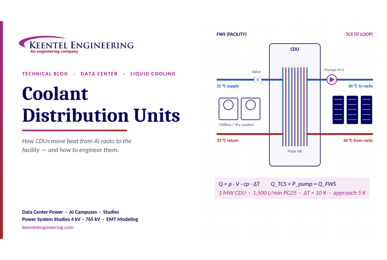
Learn how data center coolant distribution units (CDUs) work, including FWS and TCS loops, heat transfer, sizing, redundancy and liquid cooling for AI data centers.

By SANDIP R PATEL
•
October 3, 2026
Learn how BESS supports grid stability through fast frequency response, voltage support, oscillation damping, black start, grid-forming controls and EMT studies.
By SANDIP R PATEL
•
October 3, 2026
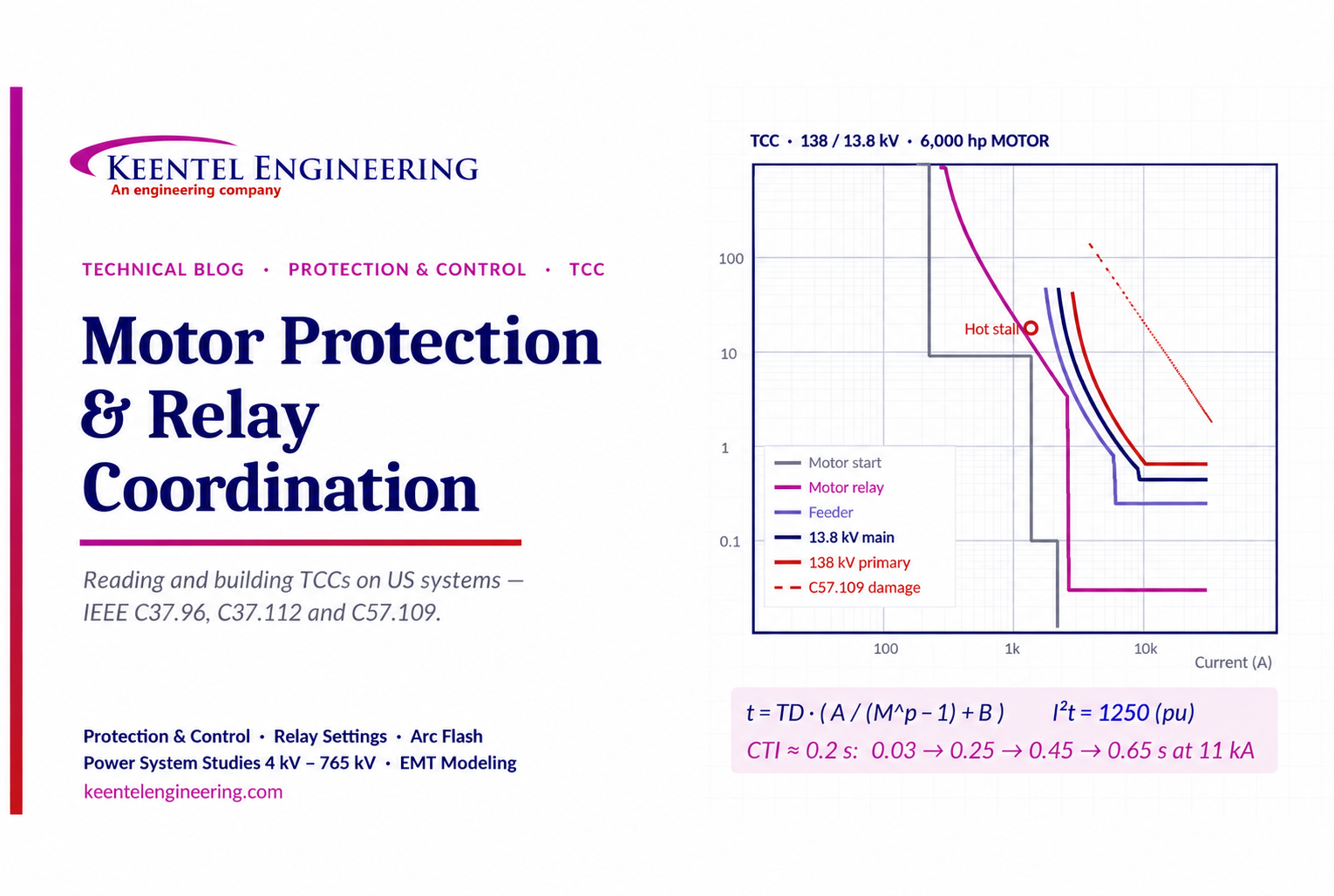
Learn motor protection and relay coordination using TCC curves, IEEE standards, transformer damage limits, CTI settings and a 138/13.8 kV example.

By SANDIP R PATEL
•
September 30, 2026
Learn NERC and ERCOT compliance requirements for natural gas power plants, including GO/GOP obligations, O&P standards, GADS reporting, and audits.

By SANDIP R PATEL
•
September 26, 2026
Learn how to prepare a MISO large-load interconnection package, including PSS®E models, BESS smoothing, harmonic data and transmission-owner requirements.





