
A Coordinated Electric System Interconnection Review—the utility’s deep-dive on technical and cost impacts of your project.
Challenge: Frequent false tripping using conventional electromechanical relays
Solution: SEL-487E integration with multi-terminal differential protection and dynamic inrush restraint
Result: 90% reduction in false trips, saving over $250,000 in downtime
The three operating regions you have to design to
| Device | Output vs voltage | Response | Best suited to | Main limitations |
|---|---|---|---|---|
| Mechanically switched capacitor or reactor | Proportional to voltage squared | Seconds; discrete steps; limited switching operations per day | Steady-state reactive supply, voltage profile, loss reduction | No dynamic capability; step voltage change on switching; capability collapses when most needed |
| Static var compensator | Capacitive branches proportional to voltage squared | A few cycles; continuously controllable | Continuous control where cost matters and deep voltage support is not the driver | Square-law capability loss; harmonic filters are part of the plant and interact with the network |
| STATCOM | Approximately proportional to voltage — constant current capability | One to two cycles closed loop; converter response faster still | Voltage stability margin, weak interconnections, fast disturbance recovery, flicker and unbalance compensation | Higher capital cost; converter losses; adds a converter and its control dynamics to the network |
| Synchronous condenser | Governed by machine capability and excitation | Excitation response in the hundreds of milliseconds; inherent inertial response instantaneous | System strength and inertia, short-circuit contribution, black start support | Rotating plant with maintenance and losses; slower controlled response than a converter |
| STATCOM with energy storage | Reactive as a STATCOM, plus real power within the storage rating | As STATCOM for reactive; real power limited by storage | Where a real power deficiency is part of the problem | Cost and complexity of the storage; different failure and maintenance profile |
| Stage | Keentel scope | Outcome |
|---|---|---|
| Screening | Series-compensation proximity, radial contingency review, UIF and short-circuit ratio screening, frequency scans | Early identification of which SSO types apply |
| Detailed studies | PSCAD/EMTDC EMT studies with vendor real-code models, impedance-based and frequency-scan analysis | Clear evidence of stability margins or risk |
| Model quality | EMT model review, benchmarking against positive-sequence models, model acceptance support | Models that system operators accept |
| Mitigation | Control retuning recommendations with vendors, SSDC and bypass logic requirements, protection and monitoring specifications | Practical, coordinated solutions |
| Interconnection support | SSR and SSO study reports for ISO and utility requirements, response to reviewer comments | Fewer delays in the interconnection process |
Resilience: designing CDUs to the facility Tier objective
Liquid cooling makes heat removal more critical, not less. Cold plates hold only seconds of thermal buffer. If TCS flow stops, processors throttle or shut down very quickly. Resilience design must therefore cover:
- Pump redundancy: N+1 pumps at minimum, with automatic changeover.
- CDU redundancy: N+1 CDUs on a common TCS header, or 2N CDUs serving A and B manifolds for fault-tolerant designs.
- Power to CDUs: dual-corded CDUs fed from A and B sources, with pumps and controls on UPS power so coolant keeps flowing through a utility failure and generator start. This is the liquid-cooling equivalent of continuous cooling.
- Facility water continuity: chilled water or condenser water must also continue, through thermal storage, UPS-backed pumps or a high enough FWS temperature that the TCS can coast on stored thermal mass for the transfer period.
- Concurrent maintainability: isolation valves so any CDU, pump, filter or manifold section can be serviced without stopping the others.
- Leak management: leak detection, drip trays, automatic isolation valves and procedures for fluid spills.
Electrical engineering considerations
CDUs and liquid-cooling plants are electrical loads with their own design requirements:
- Pump motors and VFDs. Large CDUs use variable-frequency drives on their pump motors. These introduce harmonic current that must be included in the facility's harmonic study and IEEE 519 evaluation.
- Critical mechanical load on UPS. Putting CDU pumps on UPS increases UPS and battery sizing. The mechanical UPS load must be included in redundancy and ride-through calculations.
- Feeder and protection design. Dual feeds, automatic transfer, selective coordination and arc-flash labelling apply to CDU power distribution just as they do to IT power.
- Generator transient response. CDU pumps restarting together after a transfer create motor inrush on the generators. Staged restarts and soft acceleration reduce the step load.
- Load dynamics. AI training loads can swing rapidly between high and low power. Cooling controls must track those swings without temperature overshoot, and electrical systems must handle both the IT and the cooling load changes.
Commissioning a liquid-cooled data hall
- Flush and clean the TCS piping and manifolds to the specified cleanliness, using high-purity flush water.
- Fill and vent with the specified coolant, verifying glycol concentration and chemistry.
- Pressure test for leaks at design and test pressures, including quick-disconnect fittings.
- Verify sensors and controls: flow meters, temperature sensors, pressure transmitters, leak detection and BMS points.
- Load test with heat load banks connected through the cold-plate interfaces or rack manifolds, across the operating range.
- Prove the heat balance on both loops at several load steps, and the approach temperature against the design.
- Test failure scenarios: pump failure, CDU failure, power transfer to generator, valve failure and loss of facility water, confirming temperatures stay within the IT vendor's limits.
How Keentel Engineering helps
Keentel Engineering supports data center owners, developers and EPCs with the electrical engineering that liquid-cooled facilities depend on, and coordinates with the mechanical engineer of record and cooling vendors on the integrated design.
Digital Twins, BIM and Agentic AI: Engineering the Self-Optimising Data Center
October 03, 2026 | Blog
Part A — Digital Twins, BIM and Agentic AI at a Glance
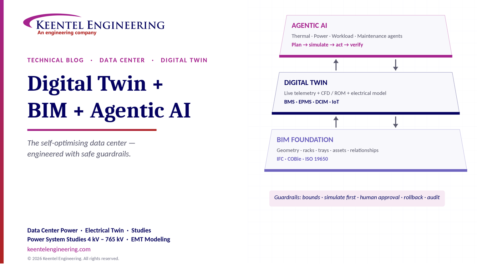
A digital twin paired with Building Information Modeling (BIM) and agentic AI turns a data center into a self-optimising cyber-physical system. BIM supplies the static geometry and asset structure, the digital twin mirrors the live operating state, and AI agents reason, plan and act across cooling, power and IT workloads, within engineered guardrails.
The three layers
| Layer | What it holds | Data sources | Changes |
|---|---|---|---|
| BIM foundation | 3D geometry, structure and space: walls, rooms, racks, cable trays, busways, pipes, equipment footprints, asset identities and relationships | Design and as-built models (IFC), asset data (COBie), laser scans | Rarely: at construction, moves, adds and changes |
| Digital twin layer | Live operating state plus physics and data-driven models: temperatures, humidity, airflow, power draw, UPS and battery status, chiller and CDU loads, breaker positions | IoT sensors, BMS, EPMS, DCIM, CMMS, IT telemetry | Continuously: seconds to minutes |
| Agentic AI orchestration | Goal-driven agents that reason, plan, simulate in the twin and execute approved actions | The twin, procedures, work-order and IT scheduling systems | Event-driven and continuous, under human-defined limits |
Three headline capabilities
- Autonomous thermal and CFD optimisation. Agents use calibrated airflow and thermal models in the twin to find hot spots and adjust CRAH fan speeds, cooling setpoints or containment, within safe bounds.
- Workload-aware energy balancing. The twin links IT workload spikes to power and cooling limits, so non-critical work can be shifted or racks power-capped before thermal or electrical thresholds are reached.
- Proactive maintenance and remediation. When a sensor or asset behaves abnormally, agents analyse its history, trace the cause through the BIM asset hierarchy and electrical topology, and raise a specific work order, or carry out a pre-approved, safe failover.
Levels of autonomy
| Level | Description | Typical use today |
|---|---|---|
| 0 — Monitor | Twin visualises live data; humans decide everything | Most DCIM deployments |
| 1 — Advise | Agents diagnose and recommend; humans act | Maintenance, capacity planning |
| 2 — Act with approval | Agents prepare actions; an operator approves each one | Setpoint changes, work orders |
| 3 — Bounded autonomy | Agents act alone within pre-approved limits and roll back if results deviate | CRAH fan speeds, supply air setpoints, workload placement |
| 4 — Supervised autonomy | Agents run defined subsystems end to end; humans supervise and can override | Mature cooling optimisation |
The goal is not to remove engineers from the loop. It is to let software handle the fast, repetitive optimisation, while people own the decisions that carry safety, reliability and contractual consequences.
Part B — Digital Twins, BIM and Agentic AI: Engineering the Self-Optimising Data Center
A practical engineering guide to the architecture, models, safeguards and roadmap for combining BIM, live digital twins and autonomous AI agents in modern data centers, with a focus on power and cooling.
Why data centers need more than monitoring
Conventional data center infrastructure management (DCIM) tools are largely reactive. They collect data, show dashboards and raise alarms after a threshold is crossed. That was workable when rack densities were 5–10 kW and loads changed slowly.
AI changes the problem. Racks now draw tens to over 100 kW, many are liquid-cooled, and training workloads can swing power across a whole hall in seconds. Power distribution, cooling, workload placement and facility operations can no longer be managed as separate domains. A decision in one, such as placing a new training job, immediately affects the others: power headroom on an A/B path, coolant temperature at a CDU, and the margin left for a failure.
A digital twin that combines a trustworthy model of the physical facility with live data, plus agents that can act on it safely, addresses that coupling.
What a digital twin is, and is not
ISO/IEC 30173:2023 establishes digital twin concepts and terminology. In engineering practice, a digital twin is a digital representation of a physical system that:
- is connected to the real system by data that updates continuously;
- includes models that can explain and predict behaviour, not just display it;
- supports decisions or actions that are fed back to the physical system.
A 3D model on its own is not a digital twin, and nor is a dashboard. The value comes from linking geometry, live data and predictive models, and from closing the loop back to operations.
Reference architecture
| Layer | Components | Common protocols and standards |
|---|---|---|
| 1. Physical and control | Sensors, CRAHs, CDUs, chillers, UPS, switchgear, PDUs, branch circuit monitoring, generators, IT servers | BACnet (BMS), Modbus, IEC 61850 (EPMS), SNMP and Redfish (IT and power devices) |
| 2. Data integration | Edge gateways, message broker, time-series database, data quality checks | MQTT, OPC UA, REST APIs |
| 3. Semantic and asset model | Asset identities, relationships, locations and point metadata linked to BIM | IFC (ISO 16739-1), COBie, Brick Schema, Project Haystack, emerging ASHRAE 223P |
| 4. Twin models | Thermal and airflow (CFD and reduced-order models), hydraulic models, electrical network model, ML surrogate and anomaly models | Simulation engines, calibrated against measurements |
| 5. Agentic AI | Specialised agents, planner, tools, guardrails, approval workflow, audit log | APIs to BMS, EPMS, DCIM, CMMS and IT schedulers |
| 6. People and process | Operators, engineers, change management, procedures | Methods of procedure, management of change |
A data center twin typically inThe semantic layer is easy to underestimate. An agent cannot reason about "CRAH-07 supplying row C" or "PDU-2B fed from UPS-B" unless those relationships exist in machine-readable form. Brick and Haystack are widely used today; ASHRAE 223P, a semantic data model for analytics and automation in buildings, completed a first public review in 2025 and is not yet a published standard.
Layer 1: the BIM foundation
BIM provides the spatial and structural baseline: architecture, structure, rooms and containment, rack layouts, cable trays and busways, piping, and the footprint of every major asset. For a digital twin, three qualities matter more than visual detail:
- As-built accuracy. The model must match what was actually installed. For existing facilities, laser scanning and field verification are usually needed.
- Asset identity. Every asset needs a unique identifier that matches the BMS point names, EPMS device IDs, DCIM records, CMMS asset numbers and the electrical one-line diagram. Inconsistent tagging is the most common cause of failed twin projects.
- Relationships. Which UPS feeds which PDU, which CRAH serves which zone, which valve isolates which CDU. These relationships let agents trace causes and consequences.
Information management standards such as the ISO 19650 series, and handover formats such as COBie, help keep BIM data structured through design, construction and operations. The model must also be kept current through management of change, or the twin will slowly drift away from reality.
Layer 2: the live twin
Telemetry
gests:
| Domain | Typical points | Typical update rate |
|---|---|---|
| Thermal and environment | Rack inlet and outlet temperatures, humidity, differential pressure across containment, leak detection | 10 s to 1 min |
| Cooling plant | CRAH fan speed, valve position, supply and return temperatures, chiller and CDU loads, coolant flow and pressure | 10 s to 1 min |
| Electrical | Breaker status, voltage, current, power and power factor at switchgear, UPS, PDUs and branch circuits; harmonics; battery health | 1 s to 1 min; events in milliseconds |
| IT | Server power, CPU and GPU utilisation and temperature, job schedules | 1 s to 1 min |
| Maintenance | Work orders, asset condition, maintenance history | Event-driven |
Models: fidelity versus speed
Different questions need different models. A practical twin uses several, each matched to the time scale of the decision:
| Model | Typical computation time | Use |
|---|---|---|
| Full computational fluid dynamics (CFD) | Minutes to hours | Design, layout changes, what-if studies, calibrating faster models |
| Reduced-order or ML surrogate thermal models | Milliseconds to seconds | Real-time optimisation and control |
| Hydraulic network model | Seconds | Coolant flow and pressure, CDU and valve behaviour |
| Electrical network model (load flow, redundancy) | Seconds | Capacity, failover headroom, switching what-ifs |
| Short-circuit, coordination and arc-flash models | Seconds to minutes, run on change | Safety checks before switching or maintenance |
| Anomaly detection and forecasting | Milliseconds to seconds | Early fault detection, load and temperature forecasting |
"Continuous CFD" is therefore usually achieved by running full CFD periodically and on change, and using fast reduced-order or machine-learning models, calibrated against CFD and sensor data, for real-time decisions.
Calibration and trust
A twin is only useful if its predictions match reality. Calibration compares model predictions with measured temperatures, flows and powers across operating conditions, and adjusts uncertain inputs such as tile flows, leakage and equipment heat loads. Ongoing validation detects drift. Agents should use model uncertainty explicitly: an action predicted to be safe with low confidence should not be executed automatically.
The electrical digital twin: the part that is often missing
Many data center twins focus on airflow and cooling. For resilience, the electrical model is just as important.
An electrical twin links the one-line diagram, protective device settings and BIM locations to live breaker status and metered loads. It can then answer questions such as:
- Is there real failover headroom? In a 2N design, each side must be able to carry the full load if the other fails.
- Where is capacity stranded? Capacity may exist upstream but be unusable because of a single PDU, breaker or busway limit.
- Is a planned switching operation safe? What will load flow, fault current and arc-flash energy be in the new configuration?
- How is the transformer or UPS ageing? Thermal loading and battery health trends indicate when to intervene.
Worked example: hidden failover risk
A pair of 2N PDUs, A and B, are each rated 300 kVA. Dual-corded racks draw 140 kVA from PDU-A and 150 kVA from PDU-B in normal operation. Each PDU looks lightly loaded, at 47% and 50%.
If PDU-A fails, PDU-B must carry the whole load:

The design still works, but with only 3% margin. If a new 20 kVA rack is added and split evenly, the survivor would need to carry 310 kVA, overloading it during a failure. A dashboard showing each PDU at about 50% would not reveal this. An electrical twin that evaluates the failure case continuously, and an agent that checks it before approving new IT placements, would.
The general rule for 2N pairs is that each side's normal load should not exceed half its rating, adjusted for the design's planned maximum loading.
Layer 3: agentic AI orchestration
What makes an agent "agentic"
A chatbot answers questions. A conventional control loop follows fixed rules. An agent combines:
- Goals, such as keeping rack inlet temperatures within limits at minimum energy;
- Perception, reading the twin's current and forecast state;
- Reasoning and planning, choosing actions and predicting their effect using the twin's models;
- Tools, APIs that read and write to the BMS, DCIM, CMMS or IT scheduler;
- Verification, checking the result and rolling back if it deviates from prediction.
A multi-agent structure
| Agent | Goal | Typical actions |
|---|---|---|
| Thermal agent | Hold inlet temperatures within limits at minimum cooling energy | Adjust CRAH fan speed, supply air or coolant setpoints, containment dampers |
| Power agent | Maintain capacity and redundancy margins | Check failover headroom, recommend or apply power caps, flag stranded capacity |
| Workload agent | Place and schedule IT work within power and thermal limits | Shift deferrable jobs, select racks or halls, coordinate power capping |
| Maintenance agent | Detect and resolve degradation early | Diagnose anomalies, create work orders, propose maintenance windows |
| Supervisor agent | Resolve conflicts and enforce policy | Arbitrate between agents, require human approval for high-consequence actions |
Guardrails: making autonomy safe
| Guardrail | Purpose |
|---|---|
| Action whitelist | Agents can only call approved tools and change approved points |
| Hard bounds and rate limits | Setpoints stay within engineered ranges; changes are gradual |
| Simulate before acting | Every action is tested in the twin first; uncertain predictions are not executed |
| Human approval tiers | High-consequence actions such as switching, transfers or disabling protection always need human approval |
| Automatic rollback | Actions are reversed if measured results deviate from prediction |
| Independent safety layer | Existing BMS and protection logic keep their limits regardless of the agent |
| Audit logging | Every observation, decision and action is recorded and reviewable |
The independent safety layer is essential. AI agents should sit above, not in place of, the BMS safety interlocks, equipment protections and electrical protection systems that already protect the facility.
Industry experience supports this model. Google and DeepMind reported in 2016 that a machine-learning recommendation system cut the energy used for cooling in Google data centers by about 40%. In 2018 they moved to autonomous control with built-in constraints and the ability for operators to intervene.
Capability 1: autonomous thermal and CFD optimisation
The thermal agent uses the twin to answer: what is the lowest-energy combination of fan speeds and setpoints that keeps every rack inlet within limits, now and over the next forecast interval?
The energy prize comes from fan physics. By the fan affinity laws, fan power varies roughly with the cube of speed:
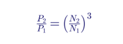
Reducing CRAH fan speed by 20% cuts fan power to about 0.8³ ≈ 51%, a saving of nearly half, as long as airflow still meets demand. Raising supply air or coolant temperatures within the IT equipment's limits allows more economiser hours and less chiller energy.
Typical constraints include the ASHRAE recommended inlet envelope of 18–27 °C for most IT classes, humidity and dew point limits, minimum airflow to every rack, and equipment-specific limits for liquid-cooled systems.
Hot spots are detected from sensors and confirmed in the model. The agent can then raise local airflow, adjust containment, or flag a physical issue such as missing blanking panels, which the BIM layout makes easy to locate.
Capability 2: workload-aware energy balancing
Because the twin knows where each workload runs, which PDU and UPS feeds it, and which CRAH or CDU cools it, it can predict the physical effect of IT decisions before they happen:
- Before a training job starts, the workload agent checks power headroom on both A and B paths, cooling capacity in the zone and failover margins, and selects racks that keep all three within limits.
- During a thermal or power constraint, such as a chiller or CDU fault, it can shift deferrable jobs or apply power caps to non-critical racks before temperatures or loads reach their thresholds.
- During utility or grid events, it can reduce flexible load to support demand response, if the operator has enabled that service.
This only works with integration into the IT scheduler or orchestration platform, and with clear rules about which workloads are flexible.
Capability 3: proactive maintenance and remediation
When a sensor or asset behaves abnormally, the maintenance agent:
- Detects the anomaly against learned normal behaviour and physics-based expectations.
- Correlates it with related signals, using the BIM and electrical relationships: the CRAH upstream, the valve controlling it, the panel feeding it.
- Diagnoses the most likely root cause, distinguishing a failed sensor from a real equipment problem.
- Acts by creating a specific work order with the asset, location, likely cause, parts and a safe maintenance window, or, for pre-approved scenarios, by executing an automated failover to redundant equipment.
Automated failover should be limited to actions covered by approved methods of procedure, tested in commissioning, and checked by the electrical twin for capacity and protection consequences. Electrical switching that changes the system's protection or arc-flash conditions should remain human-approved.
Cybersecurity: the twin is part of the attack surface
Connecting operational technology to analytics and AI agents creates new risks.
- Segmentation. Apply zones and conduits per IEC 62443, separating IT, OT and twin networks. NIST SP 800-82 Rev. 3 gives guidance for operational technology security.
- Read by default, write by exception. Most integrations should be read-only; write paths go through a controlled gateway with authentication, authorisation and logging.
- Agent security. Language-model-based agents can be manipulated through untrusted inputs, such as text in work orders or documents. Agents must treat data as data, never as instructions, and tool permissions must be narrow.
- AI governance. The NIST AI Risk Management Framework provides a structure for managing AI risks, including validity, safety, security and accountability.
- Resilience. The facility must operate safely if the twin or the agents fail. Loss of the AI layer should leave the BMS and protection systems in control.
Implementation roadmap
| Phase | Scope | Typical outcome |
|---|---|---|
| 0. Assess | Inventory systems, data quality, tagging, network architecture, goals and KPIs | Baseline and business case |
| 1. Data and BIM foundation | As-built BIM, consistent asset IDs, semantic model, secure data integration | One trusted source of asset and point data |
| 2. Monitoring twin | Live 3D visualisation linked to BIM; electrical and thermal dashboards | Shared situational awareness |
| 3. Predictive twin | Calibrated thermal, hydraulic and electrical models; forecasting and anomaly detection | What-if analysis and early warnings |
| 4. Advisory agents | Agents diagnose and recommend; humans approve | Faster diagnosis, measurable savings |
| 5. Bounded autonomy | Agents act on low-risk loops within guardrails | Continuous optimisation with oversight |
New facilities can build the twin into design: specify BIM deliverables, asset tagging, metering and open protocols in the construction documents, and commission the twin with the building. Existing facilities usually start with laser scanning and tag reconciliation, then add metering where data is missing, especially branch-circuit and rack-level power.
Measuring success
| KPI | What it shows |
|---|---|
| Power usage effectiveness (PUE) and water usage effectiveness (WUE) | Overall energy and water efficiency |
| Cooling energy per kW of IT load | Direct effect of thermal optimisation |
| Thermal compliance | Share of time rack inlets stay within the recommended envelope |
| Stranded capacity | Power and cooling capacity that cannot be used because of local limits |
| Failover headroom | Margin remaining under single-failure conditions |
| Mean time to detect and repair | Effect of proactive maintenance |
| Alarms per operator per shift | Reduction in alarm fatigue |
Common pitfalls
- Treating the twin as a visualisation project rather than a data and modelling project.
- Inconsistent asset IDs across BIM, BMS, EPMS, DCIM and CMMS.
- Uncalibrated models that operators quickly learn to distrust.
- Giving agents write access before guardrails, rollback and audit trails are in place.
- Ignoring the electrical system and its failure cases.
- Letting the BIM drift from reality after moves, adds and changes.
How Keentel Engineering helps
Keentel Engineering brings the power system engineering that a trustworthy data center twin depends on, from the utility interconnection down to branch circuits, with power system studies from 4 kV to 765 kV. Keentel works alongside the owner's twin platform provider, BIM team and mechanical engineer.
| Area | Keentel scope | Outcome |
|---|---|---|
| Electrical model foundation | Verified one-line diagrams, protective device data, load flow, short-circuit, coordination and arc-flash models suitable for twin integration | An electrical twin that reflects the real system |
| Metering and data architecture | EPMS and branch-circuit metering design, point lists, device naming aligned with BIM and DCIM | The right data, consistently tagged |
| Capacity and redundancy analysis | Failover headroom, stranded capacity and growth studies | Safe capacity decisions for new AI loads |
| Switching and maintenance safety | Pre-switching studies, arc-flash scenarios, procedure review for automated failover | Automation that stays within safe limits |
| Large-load interconnection | Utility interconnection and substation design for AI campuses | Power delivered to match the digital plan |
Planning a new AI data center or modernising an existing facility with a digital twin? Talk to Keentel Engineering at (813) 389-7871, contact@keentelengineering.com, or book a 15-minute scoping call at calendly.com/keentel-engineering/15min.
Part C — Technical FAQ: Digital Twins, BIM and Agentic AI in Data Centers
A digital representation of the facility that stays connected to live data, includes models that explain and predict behaviour, and supports decisions or actions fed back to operations. It combines geometry, assets, telemetry and simulation.
DCIM mainly collects data, tracks assets and raises alarms. A digital twin adds calibrated physical and data-driven models that predict what will happen, run what-if scenarios and support or execute optimisation. Many twins use DCIM as one of their data sources.
BIM provides the accurate geometry, spaces and asset relationships that the twin needs to locate sensors and equipment, run airflow models, trace dependencies and direct maintenance to the right place. Without it, the twin lacks a physical frame of reference.
Enough to represent airflow paths, equipment locations and relationships accurately: rooms, containment, racks, CRAHs, CDUs, piping, cable trays and busways. As-built accuracy and consistent asset identifiers matter more than fine visual detail.
IFC (ISO 16739-1) for model exchange, COBie for asset handover, the ISO 19650 series for information management, ISO/IEC 30173 for digital twin terminology, and semantic models such as Brick and Project Haystack. ASHRAE 223P is an emerging semantic standard still in development.
The BMS, electrical power monitoring system (EPMS), DCIM, branch-circuit and rack power monitoring, CDU and cooling plant controls, IT telemetry and schedulers, and the computerised maintenance management system.
BACnet for building automation, Modbus and IEC 61850 for electrical devices, SNMP and Redfish for IT and power devices, and MQTT or OPC UA for integration into the twin platform.
Full CFD usually takes minutes to hours per scenario. Continuous optimisation instead uses reduced-order or machine-learning models calibrated against CFD and sensor data, with full CFD run periodically and whenever the layout or loads change significantly.
AI systems that pursue goals by perceiving the state of a system, planning actions, using tools to execute them and verifying the results. Unlike chatbots, they act; unlike fixed control logic, they reason about changing conditions.
Low-risk, reversible, well-understood actions within engineered bounds, such as fan speeds and setpoints inside approved ranges. High-consequence actions such as electrical switching, transfers, or changes that affect protection should require human approval.
Through action whitelists, hard bounds, rate limits, simulation in the twin before acting, confidence thresholds, automatic rollback, human approval tiers and audit logging. Existing BMS interlocks and electrical protection remain as an independent safety layer.
Results depend on the starting point. Google and DeepMind reported about a 40% reduction in cooling energy from a machine-learning recommendation system in 2016. Facilities with good existing controls should expect smaller but still meaningful savings.
Fan power varies roughly with the cube of speed. Reducing speed by 20% cuts fan power by almost half, provided airflow still meets the IT demand.
Using the twin's knowledge of where workloads run and how they are powered and cooled to place, shift or cap IT work so that power and thermal limits, including failover margins, are never exceeded.
It detects anomalies early, traces them through asset and electrical relationships to a likely root cause, distinguishes sensor faults from equipment faults, and produces specific work orders with location, cause and a safe maintenance window.
Only for scenarios covered by approved procedures, tested during commissioning and checked by the electrical model for capacity and protection consequences. Many operators keep electrical transfers human-approved while automating cooling failovers.
Because failures and capacity limits in power distribution cause the most severe outages. An electrical twin checks failover headroom, stranded capacity and the safety of switching operations in real time, which thermal-only twins cannot do.
By evaluating the failure case, not just normal loading. In a 2N pair, the surviving side must carry both sides' load. Two PDUs at 47% and 50% of a 300 kVA rating would leave the survivor at 97% after a failure, with almost no room for growth.
Connecting OT systems to analytics and AI increases the attack surface. Risks include unauthorised control, data tampering and manipulation of language-model agents through untrusted inputs. Segmentation per IEC 62443, read-only defaults, controlled write gateways and strict tool permissions reduce them.
With an assessment of data quality and asset tagging, then an as-built BIM or laser scan, consistent asset IDs and secure data integration. Only after a trusted monitoring and predictive twin exists should advisory agents, and later bounded autonomy, be introduced.
References and Further Reading
Links were current at publication (October 2026).
- ISO/IEC 30173:2023, Digital twin — Concepts and terminology. ISO/IEC, November 2023.
- BSR/ASHRAE Standard 223P, Semantic Data Model for Analytics and Automation Applications in Buildings, public review notice. ASHRAE Standards Actions, June 2025.
- Google just gave control over data center cooling to an AI. MIT Technology Review, August 2018. https://www.technologyreview.com/2018/08/17/140987/google-just-gave-control-over-data-center-cooling-to-an-ai/
- ISO 16739-1 (IFC), ISO 19650 series (BIM information management). International Organization for Standardization.
- NIST SP 800-82 Rev. 3, Guide to Operational Technology (OT) Security; NIST AI Risk Management Framework 1.0. National Institute of Standards and Technology.
- IEC 62443 series, Security for industrial automation and control systems. International Electrotechnical Commission.
- ASHRAE, Thermal Guidelines for Data Processing Environments. ASHRAE TC 9.9.
| Office | Address | Phone |
|---|---|---|
| Head Office — Tampa | 400 N Ashley Dr STE #2600, Tampa FL 33602 | (813) 389-7871 |
| Austin | 5900 Balcones Drive STE 100, Austin TX 78731 | (512) 591-0752 |
| Sacramento | 1401 21st St Ste R, Sacramento CA 95811 | (916) 913-4524 |
| Baltimore | 306 W Redwood St STE 200, Baltimore MD 21201 | (410) 225-2181 |
contact@keentelengineering.com · keentelengineering.com · calendly.com/keentel-engineering/15min
State of Florida — Registry No. 36853, KEENTEL LLC, DBA: KEENTEL ENGINEERING
Copyright 1995–2026 Keentel Engineering. All Rights Reserved.

About the Author:
Sandip "Sonny" R. Patel, P.E.
IEEE Senior Member · Founder & CEO, Keentel Engineering
In 1995, Sonny Patel earned his Electrical Engineering degree from the University of Illinois. But degrees don't build legacies — action does.
For three decades, he has worked the power industry from every side of the table: 16 years as a utility engineer at Exelon/Commonwealth Edison; generation leadership across hydroelectric, industrial steam turbine, and a 9 GW renewable fleet; NERC Regional Entity Senior Compliance Engineer and Audit Team Lead, auditing some of the nation's largest utilities; and testing and commissioning lead on equipment up to 765 kV — the very top of the North American grid.Utility. Generator. Regulator. Consultant. Few engineers have seen all four seats. Fewer still have sat in them.
His experience spans nuclear, hydro, conventional generation, renewables, oil and gas, mining — and today's data centers, where he is authoring a three-book series on data center design. He is a Licensed Professional Engineer in six states and a Licensed Electrical Contractor in Florida (Unlimited EC) — he doesn't just design the work; he's qualified to stand behind its execution.Today, as Founder and CEO of Keentel Engineering, Sonny leads a nationwide team of engineers delivering substation design, power system studies, NERC compliance, and commissioning — done right, coast to coast.Three decades. Every side of the table. One standard: accountable engineering.
Services

Let's Discuss Your Project
Let's book a call to discuss your electrical engineering project that we can help you with.
About the Author:
Sandip "Sonny" R. Patel, P.E.
IEEE Senior Member · Founder & CEO, Keentel Engineering
In 1995, Sonny Patel earned his Electrical Engineering degree from the University of Illinois. But degrees don't build legacies — action does.
For three decades, he has worked the power industry from every side of the table: 16 years as a utility engineer at Exelon/Commonwealth Edison; generation leadership across hydroelectric, industrial steam turbine, and a 9 GW renewable fleet; NERC Regional Entity Senior Compliance Engineer and Audit Team Lead, auditing some of the nation's largest utilities; and testing and commissioning lead on equipment up to 765 kV — the very top of the North American grid.
Utility. Generator. Regulator. Consultant. Few engineers have seen all four seats. Fewer still have sat in them.
His experience spans nuclear, hydro, conventional generation, renewables, oil and gas, mining — and today's data centers, where he is authoring a three-book series on data center design. He is a Licensed Professional Engineer in six states and a Licensed Electrical Contractor in Florida (Unlimited EC) — he doesn't just design the work; he's qualified to stand behind its execution.
Today, as Founder and CEO of Keentel Engineering, Sonny leads a nationwide team of engineers delivering substation design, power system studies, NERC compliance, and commissioning — done right, coast to coast.Three decades. Every side of the table. One standard: accountable engineering.
Leave a Comment
Thank you for contacting us.
We will get back to you as soon as possible.
We will get back to you as soon as possible.
Oops, there was an error sending your message.
Please try again later.
Please try again later.
Related Posts

By SANDIP R PATEL
•
October 3, 2026
Engineering guide to PRC-028 disturbance recording, PRC-029 ride-through and PRC-030 event detection for inverter-based resources.

By SANDIP R PATEL
•
October 3, 2026
A practical guide to SSO classification, SSR, PEDI, Wind-SSCI, EMT analysis, mitigation and protection based on CIGRE TB 909.

By SANDIP R PATEL
•
October 6, 2026
Learn ERCOT generator testing for PFR, MOD-025 and MOD-026/027, including staged tests, capability verification, dynamic models and field testing.

By SANDIP R PATEL
•
October 3, 2026
Learn how PV string I-V curve testing identifies hidden solar performance losses, including soiling, shading, mismatch, degradation, and wiring faults.

By SANDIP R PATEL
•
October 3, 2026
Learn how active harmonic filters work, how to size AHF systems, reduce VFD harmonics, calculate losses, and meet IEEE 519 TDD limits at the PCC.
By SANDIP R PATEL
•
October 3, 2026
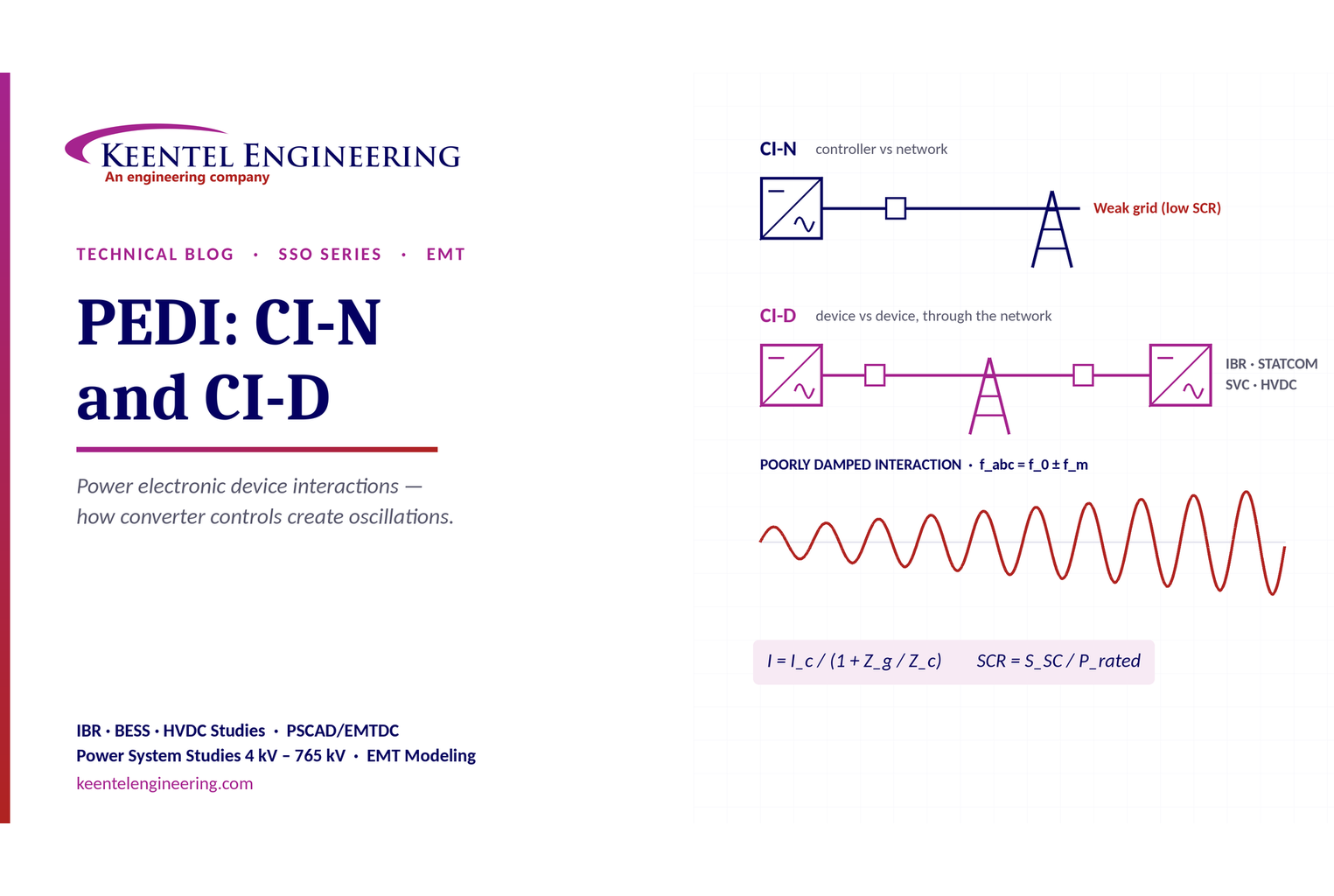
Learn power electronic device interactions (PEDI), including CI-N and CI-D, weak-grid stability, SCR, EMT studies, impedance analysis and mitigation for IBRs.
By SANDIP R PATEL
•
October 3, 2026
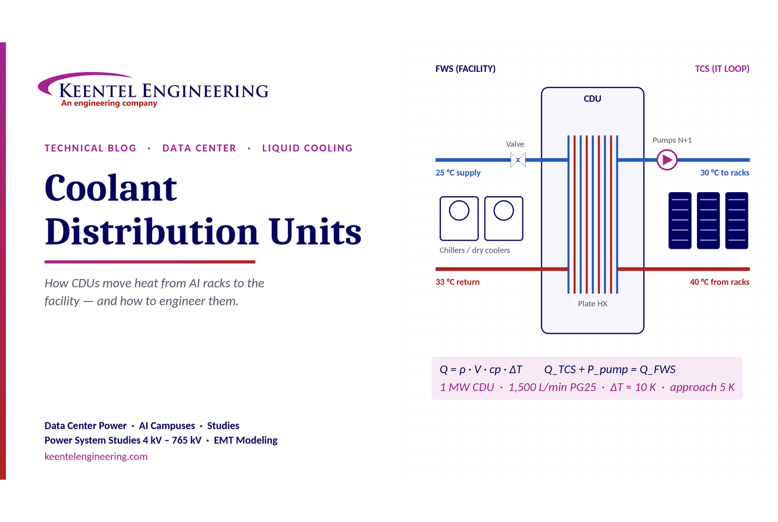
Learn how data center coolant distribution units (CDUs) work, including FWS and TCS loops, heat transfer, sizing, redundancy and liquid cooling for AI data centers.
By SANDIP R PATEL
•
October 3, 2026
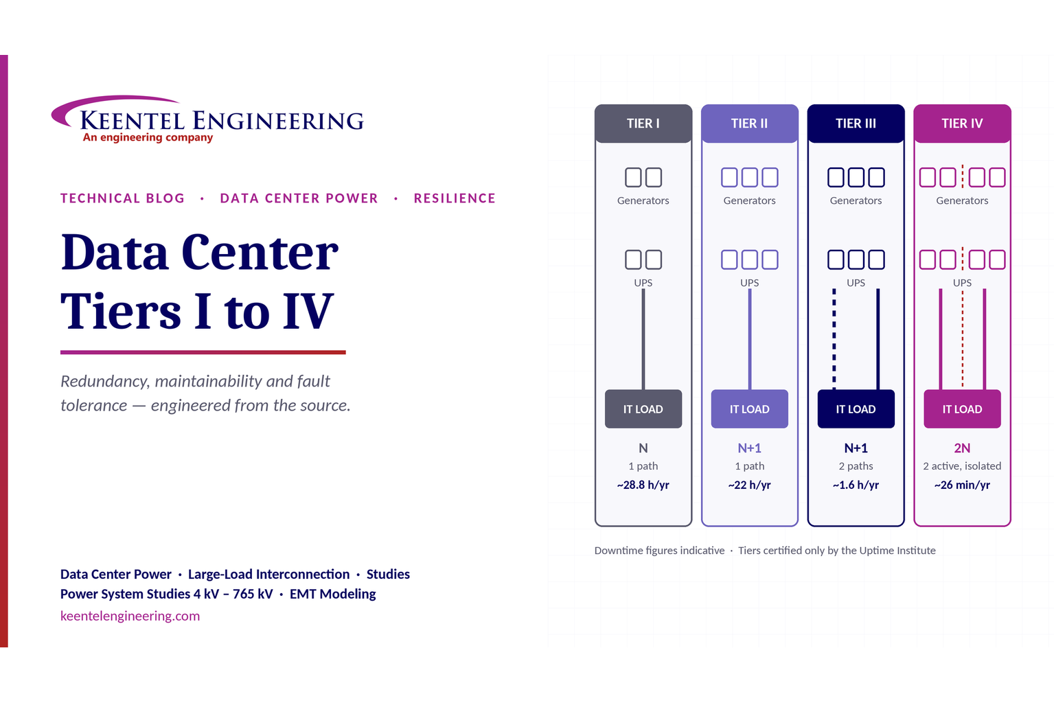
Compare Data Center Tiers I–IV, including redundancy, uptime, Tier III concurrent maintainability, Tier IV fault tolerance, UPS, generators and power design.

By SANDIP R PATEL
•
October 3, 2026
Learn how BESS supports grid stability through fast frequency response, voltage support, oscillation damping, black start, grid-forming controls and EMT studies.





