
A Coordinated Electric System Interconnection Review—the utility’s deep-dive on technical and cost impacts of your project.
Challenge: Frequent false tripping using conventional electromechanical relays
Solution: SEL-487E integration with multi-terminal differential protection and dynamic inrush restraint
Result: 90% reduction in false trips, saving over $250,000 in downtime
The three operating regions you have to design to
| Device | Output vs voltage | Response | Best suited to | Main limitations |
|---|---|---|---|---|
| Mechanically switched capacitor or reactor | Proportional to voltage squared | Seconds; discrete steps; limited switching operations per day | Steady-state reactive supply, voltage profile, loss reduction | No dynamic capability; step voltage change on switching; capability collapses when most needed |
| Static var compensator | Capacitive branches proportional to voltage squared | A few cycles; continuously controllable | Continuous control where cost matters and deep voltage support is not the driver | Square-law capability loss; harmonic filters are part of the plant and interact with the network |
| STATCOM | Approximately proportional to voltage — constant current capability | One to two cycles closed loop; converter response faster still | Voltage stability margin, weak interconnections, fast disturbance recovery, flicker and unbalance compensation | Higher capital cost; converter losses; adds a converter and its control dynamics to the network |
| Synchronous condenser | Governed by machine capability and excitation | Excitation response in the hundreds of milliseconds; inherent inertial response instantaneous | System strength and inertia, short-circuit contribution, black start support | Rotating plant with maintenance and losses; slower controlled response than a converter |
| STATCOM with energy storage | Reactive as a STATCOM, plus real power within the storage rating | As STATCOM for reactive; real power limited by storage | Where a real power deficiency is part of the problem | Cost and complexity of the storage; different failure and maintenance profile |
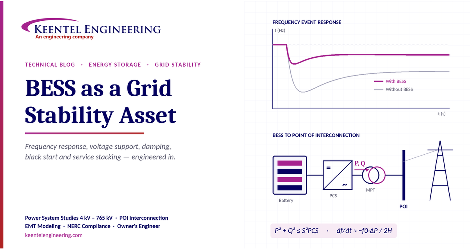
BESS as a Grid Stability Asset
October 03, 2026 | Blog
Fast frequency response, voltage support, oscillation damping, black start and service stacking — the physics, the limits and the engineering behind each service.
Part A — BESS Grid Services at a Glance
A battery energy storage system (BESS) is more than an energy-arbitrage asset. Its power electronics respond in cycles, in both directions, for active and reactive power. This makes it one of the fastest and most flexible stability resources on the grid. This section summarises the governing relationships and the nine grid services covered in this article.
Governing relationships
Rate of change of frequency (RoCoF):
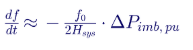
A larger power deficit, or lower system inertia, means a faster frequency decline.
Voltage sensitivity at the POI:
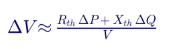
A weaker grid (higher Thévenin impedance) means a larger voltage change for the same MW or MVAr.
Converter apparent-power limit:
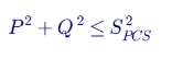
Full active power output does not leave unlimited reactive power capability.
The nine services
| # | Service | What it delivers |
|---|---|---|
| 1 | Fast frequency response (FFR) | Active power within about 0.1–2 s to limit frequency decline and raise the nadir |
| 2 | Primary frequency response and AGC | Droop response over 2–30 s, then secondary control over tens of seconds to minutes |
| 3 | Voltage support and reactive power | Fast reactive current, Volt/Var regulation, weak-grid support and fault ride-through |
| 4 | Ramp rate control | Limits dP/dt at the POI to smooth renewable output and reduce grid stress |
| 5 | Oscillation damping | Active power modulation, with phase compensation, to damp local and inter-area modes |
| 6 | Black start | Grid-forming control that energises a dead network and supports restoration |
| 7 | Dynamic reserve | Capacity and power reserve held for contingencies over seconds to hours |
| 8 | Service stacking | Several services from one asset, within PCS, current and energy limits |
| 9 | SoC management | Keeps upward and downward energy reserves available for every committed service |
Typical time scales
| Service | Typical response | Typical duration | Typical use |
|---|---|---|---|
| FFR | 0.1–2 s | 5–30 s | Limit frequency drop |
| Primary response | 2–30 s | 1–15 min | Stabilise frequency |
| Secondary (AGC) | 30 s–5 min | 15 min–hours | Generation–load balance |
| Voltage support | Cycles (inverter) to seconds (plant controller) | Continuous | Voltage control |
| Oscillation damping | 0.1–1 s | Continuous | Dynamic stability |
| Black start | Seconds–minutes | As required | System restoration |
| Dynamic reserve | Seconds–minutes | Hours | Capacity / power reserve |
Control priority by operating condition
| Condition | Typical priority | Main constraint | What limits the service |
|---|---|---|---|
| Normal operation | Economic | P² + Q² ≤ S²PCS | P and Q share converter capacity |
| Disturbance | Stability | MW and MWh headroom (SoC window) | Available SoC and service duration |
| Fault / FRT | Grid code / current priority | Id² + Iq² ≤ I²max | Current limit and grid-code P/Q priority |
MW power margin is not the same as MWh energy reserve. A BESS needs both to deliver stability services.
Part B — BESS as a Grid Stability Asset
Why a battery energy storage system is more than a price-arbitrage machine, and what it takes to engineer one that actually holds up the grid.
More than energy arbitrage
Most BESS projects get financed on energy shifting: charge when power is cheap, discharge when it is expensive. That revenue is real, but it hides the asset's most valuable property. A BESS is a power-electronic machine that can change its output in a few cycles, in either direction, for both active and reactive power.
The synchronous fleet that has stabilised the grid for a century is retiring. Its inertia, short-circuit strength and governor response are leaving with it. Inverter-based resources (IBRs) are replacing that capacity but, unless engineered to, they do not replace the stability services.
A correctly specified, modelled and tuned BESS can fill much of that gap. It can arrest frequency decline, hold voltage on a weak bus, damp oscillations, smooth renewable ramps and, if designed for it, restart a dead network. None of these come free with the battery. Each one is a design decision about the power conversion system (PCS), the plant controller, the energy reserve and the interconnection studies.
This article walks through nine grid services a BESS can provide, the physics behind each, and the engineering that turns them from a brochure claim into measurable, grid-code-compliant performance.
The physics: four equations that set the limits
Every stability service a BESS offers is bounded by four relationships. Understanding them is the difference between a plant that performs in the study and one that performs on the day.
1. Rate of change of frequency (RoCoF)
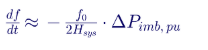
Immediately after a generator trip, before any governor acts, frequency falls at a rate set by only two things: the size of the deficit and the system inertia constant H. Halve the inertia and RoCoF doubles.
Worked example on a 60 Hz system with a 5% deficit:
| System inertia H (s) | Initial RoCoF (Hz/s) | Time to fall 0.5 Hz, unaided (s) |
|---|---|---|
| 6 (heavily synchronous) | 0.25 | ~2.0 |
| 4 | 0.375 | ~1.3 |
| 2 (high-IBR) | 0.75 | ~0.67 |
On a low-inertia system, the window for corrective action shrinks to well under a second. That is why response measured in cycles, not seconds, now matters.
2. Voltage sensitivity at the point of interconnection

Voltage change at the POI depends on the Thévenin impedance behind it. On transmission networks X/R is high, so reactive power (ΔQ) dominates voltage control. On a weak grid (low short-circuit ratio, high Zth), the same MW or MVAr swing produces a much larger voltage swing. This is also why control instability and voltage oscillation appear first at weak POIs.
3. Converter apparent-power limit
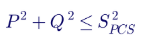
Active and reactive power share one PCS rating. A 100 MVA PCS exporting 100 MW has no reactive headroom left. At 90 MW it has about 43.6 MVAr. Specify the PCS for the full reactive requirement at rated MW, or accept that one service will be curtailed when both are called.
4. Converter current limit
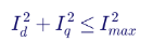
During a fault the terminal voltage collapses, so apparent power is no longer the binding limit: current is. A typical PCS can deliver only about 1.1–1.5 p.u. current, far below the 5–7 p.u. of a synchronous machine. The plant must decide how to split that current between active (Id) and reactive (Iq) components. That choice is set by the grid code, not by preference.\
The lesson across all four: full active power output does not mean unlimited reactive power capability.
Service 1 — Fast Frequency Response: buying the grid time
FFR injects active power within roughly 0.1–2 s of a frequency event. Its job is to raise the frequency nadir and slow the initial fall, so slower resources have time to arrive.
ERCOT's FFR product is a good benchmark. It triggers at 59.85 Hz, requires full response within 15 cycles (0.25 s), and must sustain for up to 15 minutes [R2]. No thermal unit can meet that. A BESS can, comfortably, if the controls are set for it.
A typical FFR control law combines two terms:
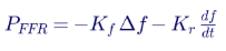
- The Δf term is a fast droop: power in proportion to frequency deviation.
- The df/dt term is synthetic ("virtual") inertia: power in proportion to the rate of fall.
The derivative term is where engineering judgement matters. Frequency measured by a phase-locked loop (PLL) is noisy and distorted by phase jumps during faults. A naive df/dt gain can trip on a fault, not a frequency event, and inject the wrong power at the wrong moment. Practical designs filter the measurement, set a RoCoF window, and block the inertial term during voltage dips.
A grid-following (GFL) inverter can only emulate inertia through this measured loop, which adds delay. A grid-forming (GFM) inverter behaves as a voltage source behind an impedance, so it resists the frequency change inherently, in the sub-transient time frame [R4].
FFR also requires reserved headroom: MW margin on the PCS and MWh in the battery in both directions.
Service 2 — Primary Frequency Response and AGC: holding the line
Once the nadir is arrested, primary frequency response (PFR) stabilises frequency over 2–30 s through droop control. Secondary control, or automatic generation control (AGC), then restores frequency and scheduled interchange over tens of seconds to minutes.
In the US, FERC Order 842 (15 February 2018) requires new interconnecting generating facilities, including electric storage, to have PFR capability. Droop must be no more than 5% and the deadband no wider than ±0.036 Hz [R1]. ERCOT uses a tighter ±17 mHz deadband with 5% droop [R2].
Two storage-specific points determine whether PFR performs:
- Droop referenced to what? For a BESS, droop should act across the full charge-to-discharge range (for example −100 to +100 MW), not just 0 to Pmax. A plant that only responds while discharging gives up half its value in over-frequency events.
- Where the droop lives. Droop implemented in the plant controller is slower than droop in the inverter. The plant controller's measurement, communication and dispatch cycle can add hundreds of milliseconds. Coordination between the two layers must be studied, not assumed.
AGC signals are mostly energy-neutral over an hour, which suits BESS well. Fast, accurate tracking of AGC signals is why storage dominates many regulation markets. It reduces how much spinning reserve conventional units must hold back.
Service 3 — Voltage Support and Reactive Power: holding the bus
A BESS inverter can source or absorb reactive power whether the battery is charging, discharging or idle. That makes it a continuous voltage resource, not just an energy one.
Voltage support works on different time scales, and a single "response time" figure can hide that distinction:
| Layer | Typical speed | What it does |
|---|---|---|
| Inverter current control | A few cycles | Dynamic reactive current injection during faults and voltage dips |
| Plant controller (PPC) Volt/Var or Q-V droop | About 1–30 s, adjustable | Regulates steady-state POI voltage around a setpoint with deadband |
| Operator or EMS setpoints | Minutes | Schedules voltage or power factor per transmission operator instructions |
IEEE 2800-2022 sets the fast layer. During ride-through, IBR units other than Type III wind must reach a reactive current step response within 2.5 cycles and settle within 4 cycles [R3]. At 60 Hz, 2.5 cycles is about 42 ms. The slower plant-level loop must be tuned so it does not fight the fast loop.
On weak grids, speed becomes a liability if gains are not studied. High Volt/Var gain on a high-Zth bus causes voltage hunting, and multiple IBR plants on the same corridor can interact with each other. Short-circuit ratio screening, followed by EMT studies where SCR is low, is how these interactions are found before energisation.
Service 4 — Ramp Rate Control: smoothing the edge
Solar output can drop sharply when a cloud passes. Wind can fall away in a gust front. Ramp rate control uses the BESS to limit dP/dt at the POI, so the grid sees a smooth slope instead of a cliff.
- What it protects: frequency on small or islanded systems, voltage flicker on weak feeders, and tap-changer and capacitor-bank wear.
- What it needs: energy sized for the worst credible ramp event, not the average. A 15-minute smoothing window on a 200 MW solar plant can demand significant MWh even if the BESS power rating is modest.
- How it is specified: many utilities state ramp limits as a percentage of nameplate per minute in the interconnection agreement. The control logic must also respect those limits on the way back up, when clouds clear.
Ramp control is often co-located with solar under a shared POI. The plant controller must then manage the combined output, not each resource separately, or the POI limit will be breached.
Service 5 — Oscillation Damping: calming the swing
Large interconnections carry electromechanical oscillation modes. Local modes, where one plant swings against the system, typically sit around 0.7–2 Hz. Inter-area modes, where whole regions swing against each other, sit around 0.1–0.8 Hz. Poorly damped modes limit transfer capability and, in the worst case, grow until protection separates the system.
A BESS can act as a power oscillation damper (POD) by modulating active power in anti-phase with the oscillation:

Here x_osc is the measured oscillation signal, such as a local bus frequency, a tie-line power flow, or an angle difference from wide-area PMU data. G_POD(s) is a washout, lead-lag compensator and gain.
The risk is real. If the phase compensation is wrong, or communication delay is longer than designed for, the BESS injects power in phase with the swing and
adds energy to it. The engineering sequence is fixed:
- Measure: use PMU or ringdown data to find the mode frequency, damping ratio and mode shape.
- Identify: run small-signal (modal) analysis to find where the BESS has the most observability and controllability.
- Tune: design phase compensation across the plausible range of operating conditions, not just one base case.
- Validate: run positive-sequence and EMT simulations, then confirm with field tests.
The same discipline applies to sub-synchronous control interaction (SSCI) near series-compensated lines. There, the risk comes from the inverter's own control loops rather than a deliberate damping function.
Service 6 — Black Start: a system design, not a battery feature
Black start is not a battery feature. It is a system design.
A BESS can only energise a dead network if it is grid-forming. A grid-following inverter needs an existing voltage to lock onto, so it cannot start a dead bus. A black-start-capable plant must:
- Establish its own voltage and frequency reference (V/f control).
- Energise its own step-up transformer and the transmission path, managing magnetising inrush through soft-start voltage ramps or point-on-wave switching.
- Pick up load in planned blocks sized to its current limit and frequency response.
- Provide a stable reference for other GFM and GFL resources to synchronise to [R4].
- Synchronise and reconnect to the wider grid without a damaging phase or frequency step.
The balance of plant matters as much as the inverter. Auxiliary power for HVAC, controls and fire suppression must survive the outage. Protection must still operate with only 1.1–1.5 p.u. of fault current available, which defeats many overcurrent-based schemes. The battery must hold enough reserved energy for the restoration plan, and the plan must be agreed with the transmission operator under its system restoration procedures.
Service 7 — Dynamic Reserve: one asset, many jobs
The time-scale table in Part A is a useful map. What it does not show is what each service demands from the plant. That is where design decisions are made:
| Service | Response | Duration | What it demands from the design |
|---|---|---|---|
| FFR | 0.1–2 s | 5–30 s | Fast inverter-level control, filtered df/dt, MW headroom both ways |
| Primary response | 2–30 s | 1–15 min | Droop across full charge–discharge range, coordinated PPC and inverter |
| Secondary (AGC) | 30 s–5 min | 15 min–hours | Telemetry and AGC interface, accurate setpoint tracking, SoC recovery logic |
| Voltage support | Cycles (inverter) to seconds (PPC) | Continuous | PCS sized for Q at rated P, tuned Volt/Var for the actual SCR |
| Oscillation damping | 0.1–1 s | Continuous | POD design, PMU input, small-signal and EMT validation |
| Black start | Seconds–minutes | As required | GFM inverters, survivable auxiliaries, inrush management, restoration plan |
| Dynamic reserve | Seconds–minutes | Hours | MWh held in reserve, forecasting, degradation-aware dispatch |
Service 8 — Service Stacking and Control Priority
Stacking services multiplies revenue, but every service draws on the same two finite pools: converter capacity (MVA and current) and stored energy (MWh). A clear priority ladder applies:
- Normal operation — economic priority. P and Q share the PCS under P² + Q² ≤ S²PCS. Market dispatch usually wins, subject to reserved reactive capability.
- Disturbance — stability priority. Frequency services take over. The binding limits are MW headroom and the SoC window.
- Fault / FRT — grid-code priority. Current is the limit (Id² + Iq² ≤ I²max). The grid code dictates whether reactive or active current takes precedence.
MW power margin ≠ MWh energy reserve. Both are required. A plant can have 100 MW of spare PCS capacity and still fail an FFR call if the battery is at minimum SoC. It can also be full of energy and fail a reactive call because the PCS is saturated by an arbitrage dispatch.
This priority logic must be written into the plant controller and the EMS, documented in the interconnection models, and agreed with the transmission operator. When the real event comes, what was modelled is what is judged.
Service 9 — SoC Management and Service Availability
Stored energy is the slowest-moving constraint in the plant. In simplified form, the available reserve is:

A 50% resting SoC is not always optimal, because services are rarely symmetric. Consider a 100 MW / 400 MWh plant:
| Commitment | Direction | Energy needed |
|---|---|---|
| 100 MW under-frequency FFR for 15 min | Discharge (up) | 25 MWh |
| 50 MW over-frequency PFR for 15 min | Charge (down) | 12.5 MWh |
| Evening peak arbitrage | Discharge (up) | Up to the rest of usable energy |
Here the optimum resting SoC sits well above 50%. In a region where over-frequency events dominate, or with heavy midday solar charging, it might sit lower. SoC limits also move with temperature and cell ageing. Usable energy at end of life can be noticeably lower than at commissioning.
The EMS must therefore co-optimise market position, reserve obligations and degradation in real time. It needs restoration logic that brings SoC back into the window after an event, without breaching ramp limits or the reserve commitment.
How Keentel Engineering Turns a BESS into a Grid Stability Asset
Every service above depends on decisions made long before the containers arrive on site. Keentel Engineering supports developers, utilities, IPPs and EPCs across the BESS lifecycle, with power system studies from 4 kV to 765 kV.
| Project stage | Keentel scope | Stability outcome |
|---|---|---|
| Feasibility and POI screening | Short-circuit ratio and system strength screening, POI capacity, hybrid co-location review | Early warning of weak-grid and control-interaction risk |
| Interconnection studies | Load flow, short circuit, transient stability, reactive capability (P-Q at POI), queue study support | Models that pass utility and ISO review the first time |
| EMT modelling | PSCAD/EMTDC plant models, weak-grid and control interaction studies, model benchmarking against positive-sequence models | Confidence that fast controls behave as designed |
| Grid code compliance | IEEE 2800 ride-through and performance assessment, NERC ride-through and modelling requirements | A plant that stays connected and responds correctly |
| Substation and electrical design | Collector system, main power transformer, POI substation, protection and control | PCS, MPT and protection sized for both P and Q duties |
| NERC compliance | Registration support and O&P standards evidence for newly registered IBR owners | Audit-ready modelling, settings and verification records |
| Owner's engineer | Specification review, PCS and PPC vendor review, factory and commissioning witness, performance testing | Delivered performance matches the contract and the model |
Studies are delivered on industry-standard platforms including PSCAD/EMTDC, PSS®E, PSLF, PowerFactory, ASPEN and ETAP, matched to what the utility or ISO requires.
For related reading, see Keentel's guides on IEEE 2800 ride-through requirements (keentelengineering.com/ieee-2800-ride-through-requirements) and IEEE 2800-2022 compliance for IBRs (keentelengineering.com/ieee-2800-2022-ibr-compliance-guide).
Planning a BESS or hybrid project? Talk to Keentel Engineering at (813) 389-7871, contact@keentelengineering.com, or book a 15-minute scoping call at calendly.com/keentel-engineering/15min.
Part C — Technical FAQ: BESS Grid Stability Engineering
1. Can a BESS actually replace synchronous inertia?
Not one for one. Synchronous inertia is physical stored kinetic energy that responds with zero delay. A grid-following BESS emulates inertia through a measured df/dt loop, so it carries measurement and control delay. A grid-forming BESS responds inherently, as a voltage source, within its current limit. In practice, fast frequency response from storage can deliver more frequency support per MW than inertia does, because it can sustain power for minutes. It does so on a slightly different time scale, which system studies must capture.
2. What is the difference between grid-following and grid-forming, and which should we specify?
A grid-following (GFL) inverter acts as a controlled current source synchronised to the grid by a PLL. It needs a reasonably strong grid. A grid-forming (GFM) inverter acts as a controlled voltage source behind an impedance. It sets its own phase angle and frequency and supports weak grids, islanding and black start. Specify GFM where the POI has low system strength, where the transmission operator asks for it, or where black start or islanding is part of the business case. Confirm that the vendor's GFM behaviour is validated in EMT models, not just claimed in a datasheet.
3. Why does reactive capability drop at full active power?
Because P and Q share one converter rating: P² + Q² ≤ S²PCS. At rated MW there is no spare MVA for reactive power unless the PCS was oversized. Most interconnection requirements define reactive capability at the POI across the full active power range, so the PCS, main power transformer and any supplementary reactive devices must be sized together.
4. What happens to active power during a fault?
Terminal voltage collapses, so the PCS hits its current limit (Id² + Iq² ≤ I²max), not its MVA limit. Most grid codes give reactive current priority during the dip, so active power falls. After the fault clears, active power must recover within the ramp-up time the grid code specifies. The order of priority and the recovery rate must be set in the inverter and represented accurately in both positive-sequence and EMT models.
5. Why do we need EMT studies if we already have PSS®E or PSLF models?
Positive-sequence models average out fast inverter dynamics, PLL behaviour and switching-level controls. They are adequate for many planning studies but can miss weak-grid control instability, sub-synchronous interactions, and fault-recovery oscillations. EMT models in PSCAD/EMTDC represent those dynamics. Many ISOs now require EMT models for IBRs, and benchmarking EMT against positive-sequence models is how model quality is proved.
6. How is short-circuit ratio used for BESS projects?
SCR is the POI fault level divided by the plant MW rating. A low SCR means the plant has strong influence over POI voltage, so its controls can destabilise it. SCR is a screening metric, not a verdict. Where several IBR plants sit electrically close, weighted SCR or similar multi-plant metrics should be used, followed by EMT studies where screening flags risk.
7. Can one BESS provide FFR, PFR and arbitrage at the same time?
Yes, if headroom is reserved for each. MW headroom on the PCS and MWh in the battery must both be held for the frequency services, in the direction each requires. The plant controller and EMS must enforce a priority order: grid-code obligations first, contracted stability services second, market dispatch last. Stacking that is not reserved this way fails at the moment it is called.
8. What droop and deadband should a BESS use for primary frequency response?
In the US, FERC Order 842 requires new generating facilities, including storage, to be capable of no more than 5% droop and no more than a ±0.036 Hz deadband. ERCOT applies 5% droop with a ±17 mHz deadband. Use the transmission operator's specific values. For storage, apply droop over the full charge-to-discharge range so the plant responds to both under- and over-frequency.
9. How fast must a BESS inject reactive current during a voltage dip?
Under IEEE 2800-2022, IBR units other than Type III wind must achieve the reactive current step response within 2.5 cycles and settle within 4 cycles. That is roughly 42 ms and 67 ms at 60 Hz. Check the applicable regional adoption of IEEE 2800 and any utility-specific requirements, which can differ.
10. Can synthetic inertia make stability worse?
Yes. A df/dt-based control acting on a noisy or phase-jumped frequency measurement can inject power in the wrong direction during faults. A poorly tuned power oscillation damper can add energy to a swing. Both risks are manageable with filtering, blocking logic during voltage dips, and phase compensation validated across operating conditions. Both require study, not default settings.
11. What does it really take for a BESS to provide black start?
Grid-forming inverters; auxiliaries that survive a total blackout; a soft-start or inrush-limiting strategy for the step-up transformer and line energisation; protection that works at limited fault current; energy reserved for the restoration plan; and agreement with the transmission operator on the restoration path and testing. A standard grid-following BESS cannot do this regardless of battery size.
12. Why is protection harder at a BESS-dominated POI?
Inverters typically limit fault current to about 1.1–1.5 p.u. and may produce controlled, non-traditional negative-sequence current. Overcurrent and distance elements set for synchronous fault levels may under-reach or misoperate. Protection settings should be checked against EMT-derived fault behaviour, particularly where the BESS may island or black start.
13. What is the right resting state of charge?
The one that keeps every committed service available in the direction it needs. Under-frequency commitments need stored energy above SOCmin; over-frequency commitments need empty capacity below SOCmax. Because these are rarely symmetric, 50% is seldom optimal. The EMS should set the target dynamically using commitments, forecasts, temperature and degradation.
14. How do cell degradation and temperature affect stability services?
They shrink usable energy and can reduce available power at temperature extremes. A plant sized for a 15-minute FFR commitment at commissioning may not hold that commitment at year 10 without augmentation. Stability commitments should be checked against end-of-life capacity and the augmentation plan, not commissioning capacity.
15. What models and data will the utility or ISO expect?
Typically a validated positive-sequence dynamic model using standard library models, an EMT model of the vendor's actual control code, a reactive capability curve at the POI, plant controller settings, and a benchmarking report showing the models agree. After commissioning, NERC modelling and verification standards require the models to reflect as-built settings, so model maintenance continues for the life of the plant.
16. Where does Keentel Engineering fit in?
Keentel supports BESS and hybrid projects from POI screening through interconnection studies, EMT modelling, IEEE 2800 and NERC compliance, substation and protection design, and owner's engineer services. The aim is a plant whose stability services are designed in, modelled correctly, and proven at commissioning.
References and Further Reading
Links were current at publication (October 2026).
Frequency response requirements
- [R1] FERC Order No. 842: Primary Frequency Response, FERC, 15 February 2018.
- [R2] Frequency Response and Ancillary Services in ERCOT, J. Matevosyan, ERCOT.
IBR performance and ride-through
- [R3] IEEE 2800-2022 Overview for ERCOT IBR Task Force, EPRI, March 2022.
Grid-forming BESS
- [R4] Specifications for Grid-forming Inverter-based Resources, UNIFI Consortium, December 2022.
- [R5] Voluntary Specification for Grid-forming Inverters, AEMO, January 2024.
- [R6]
Battery Energy Storage System Grid Forming Controls, MISO, October 2024.
Disclaimer
This article is general technical information for educational purposes. It is not engineering advice for any specific project and does not create a professional relationship. Figures such as typical response times, current limits and oscillation frequencies are indicative ranges. Project-specific requirements are set by the applicable transmission operator, ISO/RTO, grid code and interconnection agreement, and must be confirmed by project studies. Standards and tariffs change; verify the current edition before relying on any requirement quoted here.
IEEE, NERC, FERC, ERCOT, MISO, AEMO, PSCAD, PSS®E, PSLF, PowerFactory, ASPEN and ETAP are the property of their respective owners. Keentel Engineering is not affiliated with or endorsed by these organisations.

About the Author:
Sandip "Sonny" R. Patel, P.E.
IEEE Senior Member · Founder & CEO, Keentel Engineering
In 1995, Sonny Patel earned his Electrical Engineering degree from the University of Illinois. But degrees don't build legacies — action does.
For three decades, he has worked the power industry from every side of the table: 16 years as a utility engineer at Exelon/Commonwealth Edison; generation leadership across hydroelectric, industrial steam turbine, and a 9 GW renewable fleet; NERC Regional Entity Senior Compliance Engineer and Audit Team Lead, auditing some of the nation's largest utilities; and testing and commissioning lead on equipment up to 765 kV — the very top of the North American grid.Utility. Generator. Regulator. Consultant. Few engineers have seen all four seats. Fewer still have sat in them.
His experience spans nuclear, hydro, conventional generation, renewables, oil and gas, mining — and today's data centers, where he is authoring a three-book series on data center design. He is a Licensed Professional Engineer in six states and a Licensed Electrical Contractor in Florida (Unlimited EC) — he doesn't just design the work; he's qualified to stand behind its execution.Today, as Founder and CEO of Keentel Engineering, Sonny leads a nationwide team of engineers delivering substation design, power system studies, NERC compliance, and commissioning — done right, coast to coast.Three decades. Every side of the table. One standard: accountable engineering.
Services

Let's Discuss Your Project
Let's book a call to discuss your electrical engineering project that we can help you with.
About the Author:
Sandip "Sonny" R. Patel, P.E.
IEEE Senior Member · Founder & CEO, Keentel Engineering
In 1995, Sonny Patel earned his Electrical Engineering degree from the University of Illinois. But degrees don't build legacies — action does.
For three decades, he has worked the power industry from every side of the table: 16 years as a utility engineer at Exelon/Commonwealth Edison; generation leadership across hydroelectric, industrial steam turbine, and a 9 GW renewable fleet; NERC Regional Entity Senior Compliance Engineer and Audit Team Lead, auditing some of the nation's largest utilities; and testing and commissioning lead on equipment up to 765 kV — the very top of the North American grid.
Utility. Generator. Regulator. Consultant. Few engineers have seen all four seats. Fewer still have sat in them.
His experience spans nuclear, hydro, conventional generation, renewables, oil and gas, mining — and today's data centers, where he is authoring a three-book series on data center design. He is a Licensed Professional Engineer in six states and a Licensed Electrical Contractor in Florida (Unlimited EC) — he doesn't just design the work; he's qualified to stand behind its execution.
Today, as Founder and CEO of Keentel Engineering, Sonny leads a nationwide team of engineers delivering substation design, power system studies, NERC compliance, and commissioning — done right, coast to coast.Three decades. Every side of the table. One standard: accountable engineering.
Leave a Comment
Thank you for contacting us.
We will get back to you as soon as possible.
We will get back to you as soon as possible.
Oops, there was an error sending your message.
Please try again later.
Please try again later.
Related Posts

By SANDIP R PATEL
•
October 3, 2026
A practical guide to SSO classification, SSR, PEDI, Wind-SSCI, EMT analysis, mitigation and protection based on CIGRE TB 909.

By SANDIP R PATEL
•
September 30, 2026
Learn NERC and ERCOT compliance requirements for natural gas power plants, including GO/GOP obligations, O&P standards, GADS reporting, and audits.

By SANDIP R PATEL
•
September 26, 2026
Learn how to prepare a MISO large-load interconnection package, including PSS®E models, BESS smoothing, harmonic data and transmission-owner requirements.

By SANDIP R PATEL
•
September 26, 2026
Learn where storage belongs in an 800 VDC AI data center, including capacitors, flywheels, BESS, fault current, protection, grounding, and EMT design.

By SANDIP R PATEL
•
September 26, 2026
Learn how SPP’s HILL and HILLGA framework works for large-load projects, including studies, BTM generation, modeling, EMT requirements, and firm service.

By SANDIP R PATEL
•
September 25, 2026
Learn how IBR time synchronization, IEEE 2800, IRIG-B verification, and PTP solutions help meet disturbance monitoring compliance requirements.

By SANDIP R PATEL
•
September 24, 2026
Learn why continuing technical training matters in power engineering, including standards, software skills, PDH requirements, and career growth.
By SANDIP R PATEL
•
September 22, 2026
2026 ERCOT commissioning guide covering the Commissioning Plan, Checklist Parts 1–3, BESS requirements, TSP/QSE coordination, field testing and COD.

By SANDIP R PATEL
•
September 22, 2026
Learn PRC-030-1 R1 event detection requirements for inverter-based resources, SEL platforms, disturbance monitoring, and audit-ready compliance.





