
A Coordinated Electric System Interconnection Review—the utility’s deep-dive on technical and cost impacts of your project.
Challenge: Frequent false tripping using conventional electromechanical relays
Solution: SEL-487E integration with multi-terminal differential protection and dynamic inrush restraint
Result: 90% reduction in false trips, saving over $250,000 in downtime
The three operating regions you have to design to
| Device | Output vs voltage | Response | Best suited to | Main limitations |
|---|---|---|---|---|
| Mechanically switched capacitor or reactor | Proportional to voltage squared | Seconds; discrete steps; limited switching operations per day | Steady-state reactive supply, voltage profile, loss reduction | No dynamic capability; step voltage change on switching; capability collapses when most needed |
| Static var compensator | Capacitive branches proportional to voltage squared | A few cycles; continuously controllable | Continuous control where cost matters and deep voltage support is not the driver | Square-law capability loss; harmonic filters are part of the plant and interact with the network |
| STATCOM | Approximately proportional to voltage — constant current capability | One to two cycles closed loop; converter response faster still | Voltage stability margin, weak interconnections, fast disturbance recovery, flicker and unbalance compensation | Higher capital cost; converter losses; adds a converter and its control dynamics to the network |
| Synchronous condenser | Governed by machine capability and excitation | Excitation response in the hundreds of milliseconds; inherent inertial response instantaneous | System strength and inertia, short-circuit contribution, black start support | Rotating plant with maintenance and losses; slower controlled response than a converter |
| STATCOM with energy storage | Reactive as a STATCOM, plus real power within the storage rating | As STATCOM for reactive; real power limited by storage | Where a real power deficiency is part of the problem | Cost and complexity of the storage; different failure and maintenance profile |
How Can a 500 A Active Harmonic Filter Draw Only ~15 A of Real Current from the Grid?
October 03, 2026 | Blog
Part A — Active Harmonic Filters at a Glance
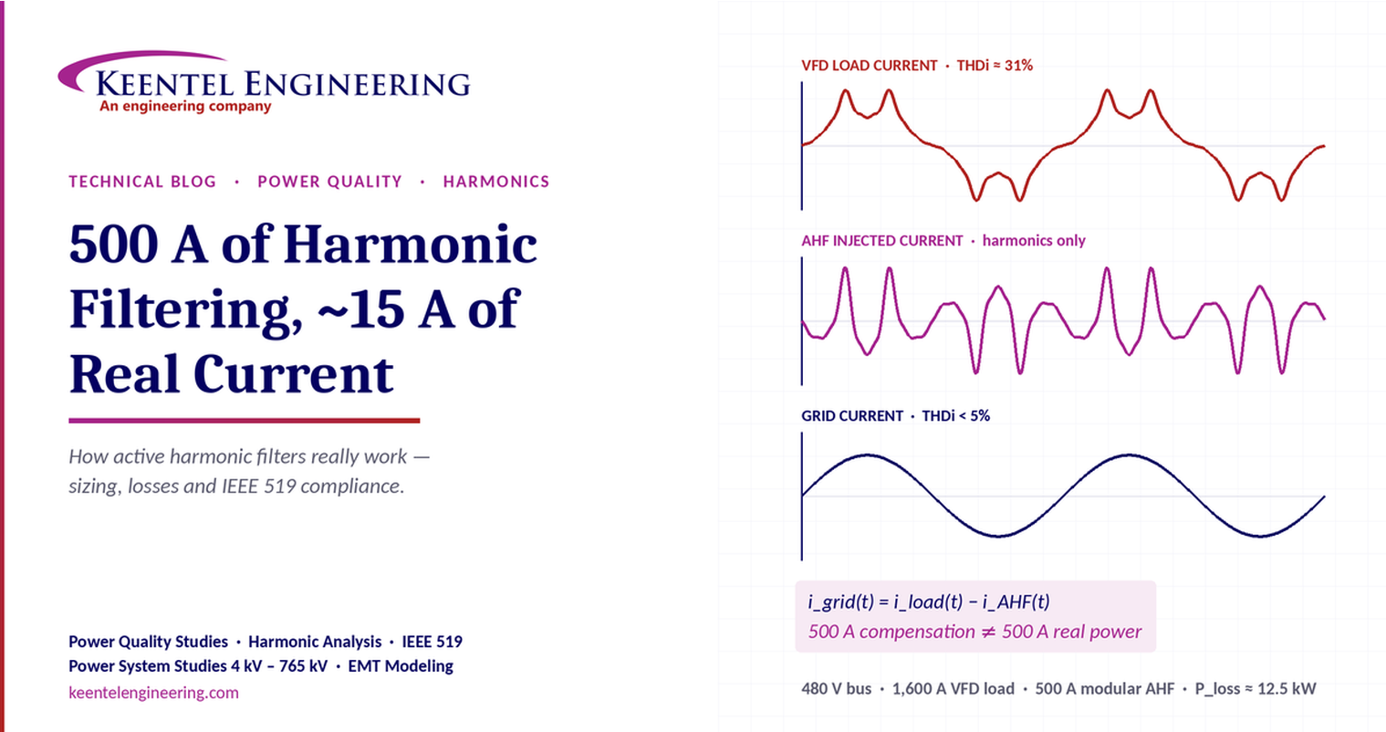
A 500 A active harmonic filter (AHF) on a 480 V bus can cancel roughly 400–500 A of harmonic current, yet take only about 15 A of real-power current from the grid. The 500 A rating is compensation capability, not continuous real-power consumption. This article explains why, works the numbers step by step, and shows how to size, apply and verify an AHF correctly.
The worked example in one table
| Quantity | Value | How it is found |
|---|---|---|
| System voltage | 480 V, three-phase | Main low-voltage switchboard |
| VFD load fundamental current (I1) | 1,600 A | Load data |
| Load current distortion (THDi) | 31% | Typical six-pulse drive without reactors |
| Load harmonic current (Ih) | 496 A | 0.31 × 1,600 |
| Load RMS current | 1,675 A | √(1,600² + 496²) |
| Target grid-side THDi | 5% | Design target after filtering |
| Residual grid harmonic current | 80 A | 0.05 × 1,600 |
| Grid RMS current | 1,602 A | √(1,600² + 80²) |
| AHF rating | 500 A (415.7 kVA) | √3 × 480 × 500 |
| AHF losses (illustrative 3%) | 12.5 kW | 0.03 × 415.7 kVA |
| Real-power current drawn by the AHF | ≈ 15 A | 12.5 kW ÷ (√3 × 480) |
500 A of compensation current is not 500 A of real-power consumption. The AHF circulates harmonic current; it consumes only its own losses.
Five things every engineer should take away
- Harmonic current carries almost no average real power. With a sinusoidal supply voltage, harmonic currents average to zero real power, so cancelling them costs only the filter's losses.
- The AHF still carries hundreds of amps at its terminals. Size its feeder, breaker and cooling for its rated current, never for the ~15 A of real-power current.
- To reach 5% THDi, the AHF injects about 416 A, not 496 A. About 80 A of harmonic current is deliberately left on the grid side.
- Kirchhoff's current law applies to instantaneous values. RMS currents of different frequencies add in quadrature, so RMS values cannot simply be subtracted.
- Compliance is judged on TDD at the point of common coupling (PCC), not on THDi at the drive terminals.
Part B — How Can a 500 A Active Harmonic Filter Draw Only ~15 A of Real Current from the Grid?
Why active harmonic filter ratings are so often misread, how to calculate what the filter really does, and what it takes to engineer an IEEE 519-compliant solution.
The question engineers keep asking
A facility adds a 500 A active harmonic filter to a 480 V switchboard feeding large variable frequency drives (VFDs). The power analyser shows the filter injecting several hundred amps, yet the plant's real power demand barely moves. Does the filter really cancel 500 A of harmonics while costing almost nothing to run?
Yes, within limits. The explanation lies in what harmonic current is, how an AHF moves it, and what the filter must pay for in real power. Getting this right matters: it decides how the filter, its feeder and its breaker are sized, and whether the facility meets its utility's harmonic limits.
Where the harmonics come from
A standard six-pulse VFD rectifies three-phase AC into DC through a diode bridge. The bridge only conducts near the peaks of the line voltage, so the drive draws current in short, sharp pulses rather than a smooth sine wave. Fourier analysis splits that pulse train into the fundamental (60 Hz) plus characteristic harmonics of order h = 6k ± 1: the 5th, 7th, 11th, 13th, 17th, 19th and so on.
Total harmonic current distortion is defined relative to the fundamental:
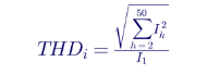
A representative spectrum for a six-pulse drive with modest DC-link inductance and no line reactor gives a THDi close to 31%:
| Harmonic order | Frequency (Hz) | % of fundamental | Current at I1 = 1,600 A (A) |
|---|---|---|---|
| 5th | 300 | 26.0 | 416 |
| 7th | 420 | 13.0 | 208 |
| 11th | 660 | 7.5 | 120 |
| 13th | 780 | 5.0 | 80 |
| 17th | 1,020 | 3.0 | 48 |
| 19th | 1,140 | 2.5 | 40 |
| Total (RSS) | — | ≈ 30.7 | ≈ 491 |
The 5th and 7th dominate. Actual spectra depend on drive design, DC-link choke, source impedance and loading, so a real project should use measured or manufacturer data.
How an active harmonic filter works
An AHF is a shunt-connected, current-controlled power converter. It has four main parts:
- Current sensors (CTs) measure either the load current (open loop) or the source current (closed loop).
- A digital controller extracts the harmonic content, typically through FFT or synchronous-reference-frame methods, and generates a compensating current reference.
- An IGBT inverter, switching at many kilohertz, produces that compensating current through an output filter.
- A DC-bus capacitor acts as the energy buffer the inverter draws from and returns to.
The AHF injects a current that is the mirror image of the load's harmonic current. At the switchboard, Kirchhoff's current law gives the source current:

When i_AHF(t) matches the harmonic part of i_load(t), the harmonics circulate between the AHF and the load. The source then supplies only the fundamental current plus the small residual left uncorrected.
Most modern AHFs use closed-loop control with CTs on the source side, so the filter corrects whatever residual it measures. Open-loop control, with CTs on the load side, responds faster but cannot correct its own errors. CT location and polarity are among the most common commissioning problems.
The worked example, step by step
Step 1 — Load current before filtering
The VFD load draws 1,600 A of fundamental current with 31% THDi:

Because currents at different frequencies are orthogonal, their RMS values add in quadrature:

Step 2 — Grid current after filtering
If the AHF reduces source-side distortion to 5% THDi, the residual harmonic current is 0.05 × 1,600 = 80 A:

The source RMS current falls by about 73 A. More importantly, the harmonic content seen by the transformer and the utility falls from 496 A to 80 A.
Step 3 — What the AHF actually injects
A common simplification shows the AHF injecting the full 496 A. But a 5% target leaves 80 A on the grid. If each harmonic is reduced in the same proportion, the injected current is the difference:

That fits inside the 500 A rating with about 17% margin. Driving the grid THDi much lower than the target uses more of the filter's capacity for little compliance benefit.
Step 4 — Compensation capability in kVA

This is converter capability, the apparent power the inverter can handle. It is not a load on the grid.
Step 5 — Real power the AHF consumes
An AHF consumes only its internal losses: IGBT conduction and switching losses, output reactor and filter losses, control power and cooling fans. Using an illustrative 3% of rated kVA:

So the filter cancels hundreds of amps of harmonic current while drawing about 15 A of real-power current from the grid.
Why the real-power cost is so small
Real power is the time average of voltage multiplied by current. When the supply voltage is a clean 60 Hz sine wave, every harmonic current averages to zero real power against it:
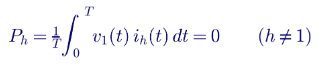
Over each cycle, the AHF absorbs energy from the bus into its DC capacitor during part of the waveform and returns it during another part. Net energy is zero apart from losses. To hold its DC-bus voltage steady against those losses, the controller draws a small in-phase fundamental current from the grid. That current is the ~15 A in this example.
When the supply voltage is itself distorted, a small harmonic real power does exist. In practice it is negligible compared with the filter's losses.
Four corrections engineers should make
| Common statement | What is actually true | Why it matters |
|---|---|---|
| "The AHF draws only 15 A" | It draws about 15 A of real-power current, but carries about 400–500 A RMS at its terminals | Feeder, breaker, CTs and cooling are sized for rated current, not 15 A |
| "The AHF injects 496 A" | To reach 5% THDi it injects about 416 A | Sizing on 496 A overstates the duty; sizing on a 0% target wastes capacity |
| "1,675 − 496 = 1,602 A" | RMS values of different frequencies add in quadrature; KCL holds for instantaneous values | Subtracting RMS values gives the wrong answer in other cases |
| "Grid current is exactly 1,602 A" | The ~15 A loss current adds to the fundamental, so grid current is about 1,615–1,617 A | Small, but it belongs in a rigorous load calculation |
Worst case, with the loss current in phase with the load fundamental:

Sizing an active harmonic filter correctly
A sound sizing process starts from data, not rules of thumb:
- Measure or model the harmonic spectrum at each load bus, across the full operating range. Partial-load operation often produces the highest THDi, while full load produces the highest harmonic amps.
- Set the target at the right point. Compliance is assessed at the PCC using TDD, so the target at the switchboard should be derived from the PCC limit, not chosen arbitrarily.
- Calculate the injection current per harmonic, then the RSS total.
- Add any reactive or unbalance duty. Many AHFs can also correct displacement power factor and phase unbalance. These functions share the same converter current:
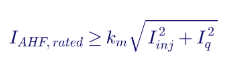
Here k_m is a design margin, commonly 1.15–1.25, covering load growth, measurement uncertainty and ageing.
- Apply derating for ambient temperature, altitude and enclosure ventilation per the manufacturer's data.
- Choose a modular arrangement. Several parallel modules give redundancy (N+1) and let capacity grow with the load.
- Set the priority for when the filter reaches its limit: harmonics first, reactive power second, unless the project requires otherwise.
A useful check on the example: 416 A of injection plus a 1.2 margin gives about 500 A. The 500 A filter is sized correctly for harmonics alone, with no spare capacity for reactive compensation.
IEEE 519 compliance: TDD, not THDi
IEEE Std 519 sets harmonic limits at the PCC, the point where the facility connects to the utility system. It limits current using total demand distortion (TDD), which divides harmonic current by the maximum demand load current (I_L), not by the instantaneous fundamental:
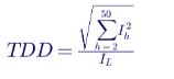
Because I_L is the facility's maximum demand, TDD is lower than THDi at partial load. A drive running at 30% load may show high THDi but still meet TDD limits.
Current distortion limits for systems rated 120 V to 69 kV:
| I SC /I L at PCC | h < 11 (%) | 11 ≤ h < 17 (%) | 17 ≤ h < 23 (%) | 23 ≤ h < 35 (%) | 35 ≤ h ≤ 50 (%) | TDD (%) |
|---|---|---|---|---|---|---|
| < 20 | 4.0 | 2.0 | 1.5 | 0.6 | 0.3 | 5.0 |
| 20–50 | 7.0 | 3.5 | 2.5 | 1.0 | 0.5 | 8.0 |
| 50–100 | 10.0 | 4.5 | 4.0 | 1.5 | 0.7 | 12.0 |
| 100–1000 | 12.0 | 5.5 | 5.0 | 2.0 | 1.0 | 15.0 |
| > 1000 | 15.0 | 7.0 | 6.0 | 2.5 | 1.4 | 20.0 |
Voltage distortion at a PCC of 1 kV or below is limited to 5% for any individual harmonic and 8% THD. The standard applies statistical evaluation of measured data rather than single snapshots.
In the worked example, if the facility's maximum demand current I_L is 2,000 A, the residual 80 A gives a TDD of 4%. That would meet even the strictest 5% TDD limit. The ISC/IL ratio, set by the utility's available fault current, decides which row applies.
Engineering and installation considerations
- Resonance with capacitor banks. Power factor correction capacitors form a parallel resonance with the source inductance. If it falls near the 5th or 7th harmonic, it can amplify distortion and blow capacitor fuses. A frequency scan should be part of any harmonic study, and detuned capacitor banks are often needed alongside an AHF.
- CT location, ratio and polarity. Incorrect CT placement is the most common reason an AHF under-performs or adds distortion. Source-side CTs must see all the load the filter is intended to correct.
- Feeder and protection sizing. Size the AHF feeder and breaker from the manufacturer's rated input current and the applicable electrical code, not from the real-power current.
- Heat rejection. At 12.5 kW of losses, the filter adds a meaningful heat load to an electrical room. HVAC sizing must include it.
- Generator operation. Standby generators have higher source impedance than the utility, so voltage distortion rises sharply on generator. The AHF must be stable on both sources, and some designs change control settings on transfer.
- Switching-frequency emissions. The AHF's own high-frequency ripple must be filtered so it does not interact with other equipment or with nearby capacitors.
- Transformer benefit. Eddy-current losses in transformers rise roughly with the square of harmonic order. Removing the 5th and 7th harmonics cuts transformer heating well beyond the simple RMS reduction and can restore capacity on a derated or K-rated transformer.
Active filters compared with other mitigation methods
| Method | Typical result at drive input (THDi) | Strengths | Limitations |
|---|---|---|---|
| AC line reactor or DC choke (3–5%) | ~30–40% | Low cost, simple, protects the drive | Rarely meets strict TDD limits on its own |
| Passive tuned (trap) filter | ~8–15% | Robust, no active electronics | Can resonate with the system; performance varies with load and source |
| Broadband passive filter | ~5–8% | Good performance per drive | Leading power factor at light load; large and heavy |
| 18-pulse drive | ~5–8% | Excellent per-drive performance | Larger drive footprint and cost; sensitive to voltage unbalance |
| Active front end (AFE) drive | ~3–5% | Low harmonics, regenerative capability | Highest drive cost; high-frequency emissions to manage |
| Active harmonic filter | Below 5% at the corrected bus | Corrects many loads at once, adapts to load changes, scalable, can correct power factor and unbalance | Active electronics need maintenance; must be sized and commissioned correctly |
Figures are indicative ranges. The best solution is often a combination, for example line reactors on every drive plus a centrally located AHF.
How Keentel Engineering helps
Keentel Engineering delivers power quality engineering from facility switchboards up to transmission interconnections, with power system studies from 4 kV to 765 kV.
| Stage | Keentel scope | Outcome |
|---|---|---|
| Measurement and diagnosis | Power quality survey planning, data review, harmonic spectrum analysis | A clear picture of where the distortion comes from |
| Harmonic study | Harmonic load flow, frequency scan, resonance analysis, IEEE 519 evaluation at the PCC | Compliance verified before equipment is bought |
| Mitigation design | AHF, passive filter, detuned capacitor and drive-technology comparison, sizing, single-line and protection design | The right solution at the right size |
| Specification and procurement support | Equipment specifications, vendor submittal review, factory test witness | Equipment that matches the study |
| Commissioning and verification | Before and after measurement plans, CT and settings review, compliance reporting | Documented, measurable results |
Facing utility harmonic limits, nuisance trips or overheating transformers? Talk to Keentel Engineering at (813) 389-7871, contact@keentelengineering.com, or book a 15-minute scoping call at calendly.com/keentel-engineering/15min.
Part C — Case Studies
The following are illustrative scenarios based on conditions typical of industrial and municipal facilities. They show how Keentel Engineering approaches harmonic problems; site details are generalised and figures are rounded.
Case Study 1 — Municipal pumping station with standby generator
Situation. A municipal water pumping station at 480 V runs several large six-pulse VFDs totalling about 1,200 hp. On utility power, operation is stable. On the standby generator, the voltage regulator hunts and drives trip on DC-bus faults during monthly tests.
Analysis. A harmonic model of both supply sources, calibrated against power quality measurements, shows TDD of about 22% at the service on utility supply. On the generator, with its much higher source impedance, voltage THD rises above 10%, distorting the voltage that the regulator and drives sense.
Engineered solution. Two parallel 300 A modular AHF units at the main motor control centre, with source-side CTs and settings validated for both utility and generator operation. Existing drive line reactors are retained.
Outcome. TDD at the service falls below 5% and voltage THD on generator falls to about 4%, removing the cause of the regulator hunting and drive trips.
Case Study 2 — Industrial facility with capacitor bank failures
Situation. An industrial plant sees repeated fuse operations on its 480 V automatic power factor correction capacitor bank after adding new VFD-driven process lines, and capacitor steps begin to fail.
Analysis. A frequency scan shows the capacitor bank, at its typical operating steps, forming a parallel resonance with the service transformer close to the 5th harmonic. The new drives excite that resonance, and the 5th harmonic voltage rises several-fold.
Engineered solution. Replace the standard capacitor bank with a detuned (7% reactor) bank, moving the resonance below the 5th harmonic, and add a 300 A AHF at the drive switchboard to bring harmonic current within the utility's limits. The AHF is set to give harmonic correction priority over reactive power.
Outcome. The resonance is removed, so capacitor fuse operations stop. Displacement power factor stays above the utility's 0.95 threshold, and harmonic current at the PCC meets the applicable IEEE 519 limits.
Case Study 3 — Plant expansion requiring IEEE 519 compliance
Situation. A manufacturer plans an expansion with about 2 MW of new VFD load. The serving utility makes IEEE 519 compliance at the PCC a condition of the upgraded service, and the original design specifies 18-pulse drives for every new motor.
Analysis. A harmonic study calculates the I_SC/I_L ratio at the PCC, sets the applicable TDD limit and models the full plant spectrum. It shows that existing and new loads together can meet the limit with standard six-pulse drives and line reactors, plus centralised active filtering on the two most heavily loaded switchboards.
Engineered solution. Six-pulse drives with 5% line reactors and two modular AHF systems sized with N+1 redundancy, supported by an equipment specification, vendor submittal review and a commissioning measurement plan.
Outcome. Post-energisation measurement over a one-week period confirms the TDD and individual harmonic limits at the PCC. The drive and filter package needs less electrical room space than the 18-pulse design and leaves spare filter capacity for future lines.
Part D — Technical FAQ: Active Harmonic Filters
An active harmonic filter is a shunt-connected power electronic converter that measures harmonic current in real time and injects an equal and opposite current. The harmonics then circulate between the filter and the load, so the upstream supply sees a nearly sinusoidal current. Unlike passive filters, an AHF adapts automatically as loads change and corrects many harmonic orders at once, typically up to the 50th.
Because 500 A is its compensation capability, not its real-power demand. Harmonic currents carry essentially no average real power against a sinusoidal supply voltage, so the AHF only consumes its own losses. In the 480 V example, 3% losses on 415.7 kVA give 12.5 kW, which is about 15 A of real-power current.
No. The filter's terminal current is the harmonic current it injects, about 400–500 A RMS in the example. Feeders, breakers and disconnects must be sized from the manufacturer's rated input current and the applicable electrical code. The ~15 A is only the real-power portion.
The 496 A figure assumes every harmonic is removed completely. Reaching a 5% THDi target leaves about 80 A of harmonic current on the grid side, so the AHF injects roughly 496 − 80 ≈ 416 A. Sizing on the design target, rather than on complete cancellation, gives a more accurate rating and preserves capacity.
Kirchhoff's current law holds for instantaneous values, and currents at different frequencies are orthogonal. Their RMS values combine as the square root of the sum of squares. That is why 1,675 − 496 does not equal 1,602, but √(1,600² + 80²) does.
THDi divides harmonic current by the fundamental current at that moment. TDD divides it by the maximum demand load current, I_L. At partial load, THDi can look high while the actual harmonic amps, and therefore TDD, are low. IEEE 519 current limits are expressed in TDD.
At the point of common coupling (PCC), the point on the utility system nearest the facility where other customers are or could be connected. Limits are not intended to apply at each drive's terminals. Many facilities, however, apply internal targets at major switchboards to protect their own equipment.
Calculate the ratio of the maximum short-circuit current at the PCC (I_SC) to the maximum demand load current (I_L). For 120 V to 69 kV systems, the TDD limit ranges from 5% for I_SC/I_L below 20 to 20% for ratios above 1,000. The utility usually provides the available fault current.
Its diode rectifier draws current only near the peaks of the supply voltage, in short pulses. Those pulses contain characteristic harmonics at orders 6k ± 1: the 5th, 7th, 11th, 13th and higher. Without a line reactor or DC choke, a six-pulse drive can exceed 80% THDi; with typical inductance it is commonly in the 30–40% range.
Current transformers feed a digital controller that extracts the harmonic components using FFT or synchronous-reference-frame techniques. In closed-loop mode, CTs on the source side let the filter correct whatever residual remains. In open-loop mode, CTs on the load side give faster response but no self-correction.
Most commercial units reach full compensation within about one to two cycles of a load change, with control loops running much faster. That is fast enough for drive load changes and most process transients. Check the manufacturer's stated response time for the specific application.
Yes, many can. Reactive current and negative-sequence current are injected by the same converter, so they share its current rating. Size the filter for the combined duty, √(I_inj² + I_q²) plus margin, and set the priority so harmonic compliance is maintained when the filter reaches its limit.
It limits its output at rated current and continues to compensate as much as it can. Harmonic distortion then rises above the target in proportion to the shortfall. A well-designed system has margin for load growth, and modular units let capacity be added later.
The running cost is its losses, commonly about 2–3% of rated kVA at full output and lower at partial output. For a 500 A, 480 V unit that is roughly 8–12.5 kW, plus cooling. Against this, the facility gains lower transformer and cable losses, freed-up transformer capacity and fewer equipment failures.
Not directly by a large amount, because harmonic current carries little real power. Savings come from reduced I²R losses in transformers and cables, recovered transformer capacity, avoided utility penalties, and fewer failures of capacitors, motors and electronics. If the AHF also corrects power factor, it can reduce power factor charges.
The AHF itself does not create resonance, but existing standard capacitor banks can form a parallel resonance with the source inductance near the 5th or 7th harmonic. A frequency scan should check this. Detuned capacitor banks, or using the AHF for reactive compensation instead of capacitors, avoid the problem.
Usually at the switchboard or motor control centre that feeds the main non-linear loads, with CTs placed to see all the load current it must correct. Central installation corrects many drives with one filter. Local installation at a single large drive gives the best result for that drive and reduces cable heating upstream.
Yes, if it is selected and set for it. Generators have higher source impedance than the utility, so the same harmonic current produces more voltage distortion. The filter must remain stable on the weaker source. Some designs use separate parameter sets for utility and generator operation.
Measure before and after installation with a power quality analyser at the PCC and at the corrected bus. Record over a representative operating period, typically at least a week, and evaluate using the statistical approach in IEEE 519. Confirm CT polarity, ratio and phase rotation at commissioning, because errors there are the most common cause of poor results.
An AHF suits facilities with many existing drives, mixed or changing loads, limited space, or a need to correct power factor and unbalance as well. 18-pulse or active-front-end drives suit new single large drives where per-drive performance or regeneration matters. A harmonic study comparing the options at the PCC usually shows the most economical combination.
References and Further Reading
Links were current at publication (October 2026).
- IEEE Std 519, IEEE Standard for Harmonic Control in Electric Power Systems. IEEE Standards Association (current edition 2022).
- A Practical and Effective Way of Applying IEEE Std 519-2014 Harmonic Limits, Mirus International.
- Power Quality: IEEE 519-2022 overview, powerquality.blog, June 2023.
Disclaimer
This article is general technical information for educational purposes. It is not engineering advice for any specific project and does not create a professional relationship. Harmonic spectra, loss percentages, response times and mitigation performance figures are indicative values; project-specific results depend on the actual system, equipment and utility requirements, and must be confirmed by measurement and study. Verify the current edition of any standard before relying on a limit quoted here.
Case studies are illustrative scenarios based on typical project conditions, not records of specific client projects. Figures are rounded and indicative.
IEEE and IEEE Std 519 are the property of the Institute of Electrical and Electronics Engineers. Keentel Engineering is not affiliated with or endorsed by IEEE or any equipment manufacturer.

About the Author:
Sandip "Sonny" R. Patel, P.E.
IEEE Senior Member · Founder & CEO, Keentel Engineering
In 1995, Sonny Patel earned his Electrical Engineering degree from the University of Illinois. But degrees don't build legacies — action does.
For three decades, he has worked the power industry from every side of the table: 16 years as a utility engineer at Exelon/Commonwealth Edison; generation leadership across hydroelectric, industrial steam turbine, and a 9 GW renewable fleet; NERC Regional Entity Senior Compliance Engineer and Audit Team Lead, auditing some of the nation's largest utilities; and testing and commissioning lead on equipment up to 765 kV — the very top of the North American grid.Utility. Generator. Regulator. Consultant. Few engineers have seen all four seats. Fewer still have sat in them.
His experience spans nuclear, hydro, conventional generation, renewables, oil and gas, mining — and today's data centers, where he is authoring a three-book series on data center design. He is a Licensed Professional Engineer in six states and a Licensed Electrical Contractor in Florida (Unlimited EC) — he doesn't just design the work; he's qualified to stand behind its execution.Today, as Founder and CEO of Keentel Engineering, Sonny leads a nationwide team of engineers delivering substation design, power system studies, NERC compliance, and commissioning — done right, coast to coast.Three decades. Every side of the table. One standard: accountable engineering.
Services

Let's Discuss Your Project
Let's book a call to discuss your electrical engineering project that we can help you with.
About the Author:
Sandip "Sonny" R. Patel, P.E.
IEEE Senior Member · Founder & CEO, Keentel Engineering
In 1995, Sonny Patel earned his Electrical Engineering degree from the University of Illinois. But degrees don't build legacies — action does.
For three decades, he has worked the power industry from every side of the table: 16 years as a utility engineer at Exelon/Commonwealth Edison; generation leadership across hydroelectric, industrial steam turbine, and a 9 GW renewable fleet; NERC Regional Entity Senior Compliance Engineer and Audit Team Lead, auditing some of the nation's largest utilities; and testing and commissioning lead on equipment up to 765 kV — the very top of the North American grid.
Utility. Generator. Regulator. Consultant. Few engineers have seen all four seats. Fewer still have sat in them.
His experience spans nuclear, hydro, conventional generation, renewables, oil and gas, mining — and today's data centers, where he is authoring a three-book series on data center design. He is a Licensed Professional Engineer in six states and a Licensed Electrical Contractor in Florida (Unlimited EC) — he doesn't just design the work; he's qualified to stand behind its execution.
Today, as Founder and CEO of Keentel Engineering, Sonny leads a nationwide team of engineers delivering substation design, power system studies, NERC compliance, and commissioning — done right, coast to coast.Three decades. Every side of the table. One standard: accountable engineering.
Leave a Comment
Thank you for contacting us.
We will get back to you as soon as possible.
We will get back to you as soon as possible.
Oops, there was an error sending your message.
Please try again later.
Please try again later.
Related Posts

By SANDIP R PATEL
•
October 3, 2026
A practical guide to SSO classification, SSR, PEDI, Wind-SSCI, EMT analysis, mitigation and protection based on CIGRE TB 909.

By SANDIP R PATEL
•
October 3, 2026
Learn how PV string I-V curve testing identifies hidden solar performance losses, including soiling, shading, mismatch, degradation, and wiring faults.

By SANDIP R PATEL
•
October 3, 2026
Learn how BESS supports grid stability through fast frequency response, voltage support, oscillation damping, black start, grid-forming controls and EMT studies.

By SANDIP R PATEL
•
September 30, 2026
Learn NERC and ERCOT compliance requirements for natural gas power plants, including GO/GOP obligations, O&P standards, GADS reporting, and audits.

By SANDIP R PATEL
•
September 26, 2026
Learn how to prepare a MISO large-load interconnection package, including PSS®E models, BESS smoothing, harmonic data and transmission-owner requirements.

By SANDIP R PATEL
•
September 26, 2026
Learn where storage belongs in an 800 VDC AI data center, including capacitors, flywheels, BESS, fault current, protection, grounding, and EMT design.

By SANDIP R PATEL
•
September 26, 2026
Learn how SPP’s HILL and HILLGA framework works for large-load projects, including studies, BTM generation, modeling, EMT requirements, and firm service.

By SANDIP R PATEL
•
September 25, 2026
Learn how IBR time synchronization, IEEE 2800, IRIG-B verification, and PTP solutions help meet disturbance monitoring compliance requirements.

By SANDIP R PATEL
•
September 24, 2026
Learn why continuing technical training matters in power engineering, including standards, software skills, PDH requirements, and career growth.





