
A Coordinated Electric System Interconnection Review—the utility’s deep-dive on technical and cost impacts of your project.
Challenge: Frequent false tripping using conventional electromechanical relays
Solution: SEL-487E integration with multi-terminal differential protection and dynamic inrush restraint
Result: 90% reduction in false trips, saving over $250,000 in downtime
ERCOT enforces all of the above through simulation, which means your model is your compliance case. The bar is now high:
- Whole-facility scope. The model must represent everything the IT load, the UPS and power conversion, the cooling plant, the protection and control systems in formats compatible with ERCOT's study platforms (PSS/E, PSCAD, TSAT).
- Real control loops, not approximations. Generic textbook representations are unacceptable. The model must capture the actual inner control behavior of your power electronics.
- Hardware-validated converter models. For electronic loads, the PSCAD model must be benchmarked against actual hardware testing including voltage ride-through and subsynchronous response. A model assembled from standard PSCAD library blocks fails by definition, because a generic block has never been tested against your vendor's hardware. The good news: validation is a hardware-type test, so results for a given converter product are reusable across every facility that uses it.
- Format migration. Facilities that previously submitted the older composite load model (CMLD) format must transition to EPRI's PERC1 format.
- Three checkpoints. Models are reviewed before the stability study begins (no model, no study), before each quarterly stability assessment, and for electronic loads one final time before energization, when you must submit as-built models with a documented comparison against the previously studied data and a sworn attestation that the model matches actual field settings. ERCOT's review takes 10 business days, extendable by 20 put it on your critical path.
- A living obligation. Change your technology, controls, or relay settings in a way that affects ride-through including converting a crypto mining site to an AI data center — and you've triggered a new interconnection study, even if your megawatts don't change.
| Parameter | Detail |
|---|---|
| System | 230 kV / 138 kV transmission corridors, wind and wet-snow icing exposure |
| Data basis | 15 years of minute-resolution forced-outage records + regional weather observations |
| Core methods | Event grouping, MVA performance curves, time-to-95%-restore, area outage rate curves, fragility modeling, rerun-history benefits, exceedance and log-domain risk metrics |
| Headline result | ≈85% of maximum resilience benefit at 60% of original capital; worst-event restoration window cut from 11 days to 5 in rerun-history terms |
| Decision supported | Capital portfolio selection; resilience plan filing; post-investment verification framework |
| System / Topic | Governing Standard(s) | What It Controls |
|---|---|---|
| Overall plant electrical distribution | IEEE 141 (Red Book); IEEE 666 | Distribution architecture, voltage selection, design of generating station auxiliary service systems |
| Power system studies | IEEE 399 (Brown Book); IEEE 551 | Load flow, symmetrical/asymmetrical short circuit, motor starting methodologies down to the lowest LV panelboard |
| Protection & coordination | IEEE 242 (Buff Book); IEEE 3004.5; IEEE C37 series | Generator relaying (21, 59N, 87G), time-current coordination, selective clearing between LV and MV tiers |
| GSU / UAT / SST transformers | IEEE C57.12.00 and C57 family | Transformer ratings, impedance, testing, loading |
| HV switchyard breakers | IEEE C37.06 | AC high-voltage circuit breaker preferred ratings |
| MV switchgear (13.8 kV) | IEEE C37.20.2; IEEE C37.20.7 | Metal-clad construction, compartmentalization, vacuum breakers; arc-resistant design with plenum venting |
| MV cable | UL 1072; ICEA S-93-639 (NEMA WC 74) | Type MV-105 shielded cable, 133% insulation level for HRG systems |
| LV switchgear (480 V) | IEEE C37.13; UL 1558 | Metal-enclosed LV power circuit breaker switchgear to 635 V, draw-out ACBs with electronic trip units |
| Motor control centers | UL 845; NEMA ICS 18 | LV-MCC construction, MCCB/MCP protection for motors under ~200 HP |
| Motors | NEMA MG-1 | Motor performance, starting characteristics, service factors |
| DC & battery systems | IEEE 485; IEEE 946 | Lead-acid battery sizing (125/250 VDC), DC auxiliary system design |
| Grounding | IEEE 80; IEEE 142 (Green Book) | Ground grid step/touch potential limits; system grounding including high-resistance grounding |
| Lightning protection | IEEE 998 | Direct-stroke shielding of switchyard and outdoor generator structures |
| Arc flash & electrical safety | IEEE 1584; NFPA 70E | Incident energy calculation; worker safety boundaries and PPE |
| Fire protection | NFPA 850 | Fire protection and risk management for combustion turbine generating plants |
| Installation code | NEC (NFPA 70); NESC | Wiring methods inside the plant fence; overhead/outdoor clearances at the switchyard |
| Interconnection & compliance | FERC LGIP; NERC MOD-025/026/027, PRC-019/024/029, FAC-008 | Interconnection process, model validation, protection/ride-through coordination, facility ratings |
| IFC / Construction Deliverable | Purpose |
|---|---|
| Stamped IFC packages | Legal basis for construction; P.E. responsible charge |
| Final relay settings & TCCs | Protection as-installed matches the coordination study |
| Calculation archive | Owner records; NERC audit evidence trail |
| Commissioning procedures | Safe, sequenced energization; MOD field testing |
| Construction support | RFIs, field changes, FAT/SAT witness |
| As-builts & model handoff | Operating baseline; future study currency |
| Metric | Outcome |
|---|---|
| Defects found pre-occupancy | Three topology defects and one settings-mismatch family corrected before load migration; the shared-switchboard defect alone would have invalidated the concurrently-maintainable claim on day one |
| IST findings | Fourteen additional discrepancies surfaced under scenario testing (control logic, alarm mapping, one generator sequencing fault) — all closed before handover instead of during operations |
| Black-building test | Passed on second execution; the first attempt exposed the generator sequencing fault under true block load, exactly the failure the compressed plan would never have found |
| Handover quality | Operations team certified on the actual failure scenarios; corrected EOPs and settings documentation delivered as controlled documents |
| Business outcome | Occupancy proceeded three weeks behind the original date — against an independent estimate that the uncorrected sequencing fault carried a high probability of a full facility outage within the first year |
Sizing AC Cables in a Utility-Scale Solar PV Plant
Aug 22, 2026 | Blog
The US / NEC Method
Power Systems Design | Technical Guide, FAQ and Case Studies | August 2026
There is a well-circulated infographic on AC cable sizing for PV plants. It lays out four checks — ampacity, voltage drop, derating, short-circuit withstand — and works an example from a 350 kW inverter to a 300 mm² copper cable. The framework is right. The sequencing is right. It is a better starting point than most.
It is also written to IEC practice, and if you carry it onto a US project it will produce conductors that are the wrong material, the wrong size, and non-compliant for reasons the graphic never mentions.
This article rebuilds the whole method on NEC 2023 (with 2026 changes flagged), in AWG and kcmil, with aluminum conductors, at real US inverter voltages — and works two complete examples: a 240 A string-inverter AC output circuit and a 2,500 kVA central inverter block. Along the way we will be specific about what the popular version gets wrong, because two of its errors are the kind that survive design review and show up as a re-pull.
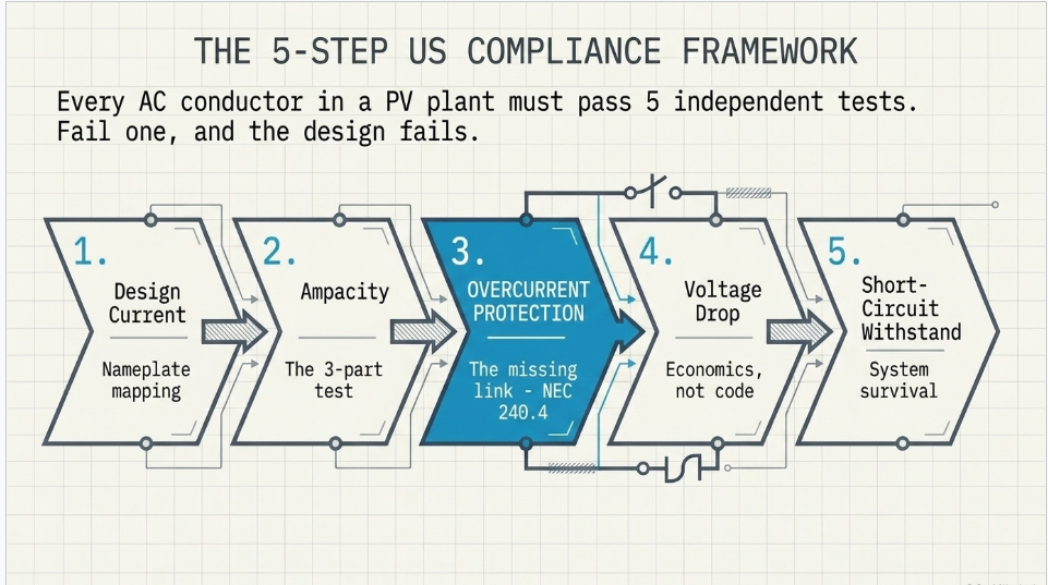
1. The four checks — and the one that is missing
Any AC conductor in a PV plant has to pass four independent tests. Fail any one and the conductor is wrong, no matter how comfortably it passes the other three.
| Check | Question | Governing |
|---|---|---|
| Ampacity | Can it carry continuous current without exceeding its insulation rating? | NEC 690.8, 310.16, 110.14(C) |
| Voltage drop | Does the delivered voltage stay inside the operating window, and are the I²R losses economic? | NEC Code |
| Short-circuit withstand | Does it survive the prospective fault until the breaker clears? | ICEA P-32-382 |
| Overcurrent protection | Is it protected at or below its ampacity? | NEC 240.4 |
The popular graphic covers the first three. It omits the fourth almost entirely, and inside the first it omits the single most important number in US PV conductor sizing: 125%.
NEC 690.8(B)(1) requires that PV circuit conductors have an ampacity, before the application of adjustment and correction factors, of not less than 125% of the maximum current determined in 690.8(A). This is the continuous-duty multiplier, and it exists because a PV plant runs at full output for hours at a time — unlike almost any other load on a distribution system.
Skip it and every conductor in your plant is undersized by 25%. There is no derating stack, no cable-tray factor, and no clever conductor material that recovers from that.
Edition note. 690.8(A)(3) is the inverter-output-circuit current rule in the 2017, 2020 and 2023 NEC.
The 2026 NEC restructured 690.8(A), and the same rule now sits at 690.8(A)(1)(c). Cite the subsection with its edition, or cite the rule by name.
2. Step 1 — Design current: use the nameplate, not the power formula
The graphic starts with I = P / (√3 × V × PF). For a motor or a general load, fine. For a PV inverter, the NEC tells you not to.
NEC 690.8(A)(3) (2023): for the inverter output circuit, the maximum current shall be the inverter continuous output current rating. That is a value on the nameplate. You look it up; you do not derive it.
This is not pedantry. Three things go wrong when you compute it instead.
The power factor assumption is usually wrong
The graphic assumes PF = 1.0. Most US interconnection agreements require the plant to operate across a 0.95 leading to 0.95 lagging power factor range for voltage support. An inverter is a kVA-limited device: at 0.95 PF it still pushes its full rated current, it just delivers less real power. If you size the conductor from kW at unity power factor and the plant is later required to run at 0.95, your design current was 5.3% low before you started. See Case Study 3.
The AC voltage is not a single number
A 4,200 kVA SMA Sunny Central UP-US is nominally 630 V but operates across 504–756 V. Current at the low end of that window is materially higher than current at nominal. The nameplate continuous output current rating already accounts for this. Your formula does not.
Inverters derate on temperature
Continuous output at 50 °C ambient is not continuous output at 25 °C. The nameplate rating is defined; a back-calculation from DC nameplate is not.
Get the rating from the datasheet. If the datasheet is not final, do not finalize the cable schedule.
3. Step 2 — Ampacity: two tests, then a ceiling
US ampacity is a three-part exercise, and the popular guide does only the middle part.
The two-part 690.8(B) test
- 690.8(B)(1) — ampacity, before adjustment and correction factors, ≥ 125% × maximum current
- 690.8(B)(2) — ampacity, after adjustment and correction factors, ≥ maximum current
You compute both and take the larger conductor. On a hot site with heavy derating, (B)(2) can govern. On a cool site in a single conduit, (B)(1) governs. Neither one alone is the answer.
Which table
Table 310.16 — "Ampacities of Insulated Conductors with Not More Than Three Current-Carrying Conductors in Raceway, Cable, or Earth (Directly Buried)," based on 30 °C (86 °F) ambient.
Note the renumbering: Article 310 was reorganized in the 2020 NEC. What older references call Table 310.15(B)(16) is now Table 310.16; 310.15(B)(17) is now 310.17 (free air). Medium-voltage conductors moved out of Article 310 entirely — to Article 311 in 2020, and then to Article 315, "Medium Voltage Conductors and Cable," in the 2023 NEC. Your collector system lives there, not in 310.
Working values for utility-scale PV, Table 310.16, three current-carrying conductors, 30 °C:
| Size | Cu 75 °C | Cu 90 °C | Al 75 °C | Al 90 °C |
|---|---|---|---|---|
| 4/0 AWG | 230 | 260 | 180 | 205 |
| 250 kcmil | 255 | 290 | 205 | 230 |
| 350 kcmil | 310 | 350 | 250 | 280 |
| 500 kcmil | 380 | 430 | 310 | 350 |
| 600 kcmil | 420 | 475 | 340 | 385 |
| 750 kcmil | 475 | 535 | 385 | 435 |
| 1000 kcmil | 545 | 615 | 445 | 500 |
The ceiling almost everyone forgets: NEC 110.14(C)
This is the most consequential difference between the graphic and US practice.
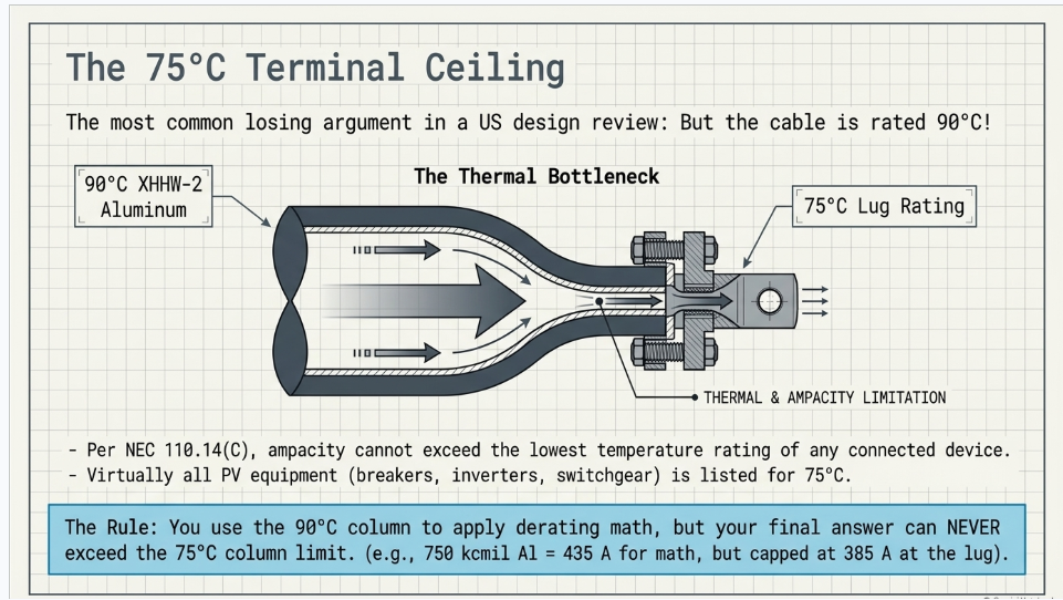
The graphic reads ampacity straight off a 90 °C XLPE table and derates from there. In the US you cannot do that, because NEC 110.14(C) requires conductor ampacity to be selected so as not to exceed the lowest temperature rating of any connected termination, conductor, or device.
- Circuits rated 100 A or less, or marked for 14 AWG–1 AWG → 60 °C column, unless the equipment is listed and identified for higher
- Circuits rated over 100 A, or marked for conductors larger than 1 AWG → 75 °C column
Virtually all utility-scale PV AC equipment — breakers, AC combiners, inverter terminals, switchgear lugs — is listed for 75 °C terminations. So:
You may use the 90 °C column as the basis for applying correction and adjustment factors. You may not end up above the 75 °C ampacity.
XHHW-2 aluminum is a 90 °C wet-and-dry conductor. You buy it for the derating headroom, not for the ampacity. A 750 kcmil aluminum conductor is a 435 A conductor for derating math and a 385 A conductor at the lug.
This single rule is why US conductor schedules run larger than an IEC-trained engineer expects, and why "but the cable is rated 90 °C" is the most common losing argument in a US design review.
4. Step 3 — Correction and adjustment: what counts, and what does no
The graphic multiplies five factors together:
| Factor in the graphic | Value | Verdict |
|---|---|---|
| Ambient temperature (40 °C) | 0.91 | Legitimate |
| Installation method (in cable tray) | 0.91 | Not a factor — see below |
| Grouping of cables (3 loaded circuits) | 0.80 | Legitimate, but see double-count |
| Cable spacing (touching) | 0.90 | Double-counts with grouping |
| Soil thermal resistivity (1.5 K·m/W) | 0.95 | Does not apply to a tray installation |
| Total | stated as 0.60 | Actually 0.566 |
Three separate problems, in increasing order of seriousness.
The arithmetic is wrong. 0.91 × 0.91 × 0.80 × 0.90 × 0.95 = 0.566, not 0.60. A 6% error in the conservative direction, presented as an equality.
Installation method is not a multiplier. In-tray versus in-conduit versus direct-buried determines which table and which column you read. It is not a coefficient you apply on top of a value you already read from the correct table. Applying 0.91 for "in cable tray" to a tray ampacity is double-counting the same physics.
Soil thermal resistivity does not apply to cable in a tray. The example route is explicitly "In Cable Tray." Soil rho is a buried-cable parameter. This factor is simply from a different problem.
And the same double-count logic applies to spacing versus grouping: IEC 60364-5-52 grouping factors are already tabulated by arrangement, including touching. Multiplying a grouping factor by a separate "touching" factor applies the same derate twice.
What the NEC actually gives you
Two factors, and they are cleanly separated. Ambient correction — Table 310.15(B)(1) (for the 30 °C-based tables):
| Ambient | 75 °C conductor | 90 °C conductor |
|---|---|---|
| 36–40 °C | 0.88 | 0.91 |
| 41–45 °C | 0.82 | 0.87 |
| 46–50 °C | 0.75 | 0.82 |
Two traps here. The NEC works in bands, not point values — 44 °C and 41 °C get the same factor. And there are two correction tables: 310.15(B)(1) for the 30 °C-based tables (310.16) and 310.15(B)(2) for the 40 °C-based free-air and medium-voltage tables. They are routinely confused online. Using the wrong one on a desert site is a real error with a real magnitude.
Adjustment for conductor count — 310.15(C)(1), applies
to more than three current-carrying conductors:
| Current-carrying conductors | Factor |
|---|---|
| 4–6 | 80% |
| 7–9 | 70% |
| 10–20 | 50% |
| 21–30 | 45% |
| 31–40 | 40% |
| 41 and above | 35% |
For a three-phase, three-wire inverter output circuit in its own conduit, there are exactly three current-carrying conductors and no adjustment applies. The EGC is not a current-carrying conductor.
Cable tray is its own rule set
If you are in tray — and in utility-scale PV you often are — the governing section is NEC 392.80, not 310.15(C)(1).
- 392.80(A)(1), multiconductor cables: base ampacity from Table 310.16. 310.15(C)(1) adjustment applies only to cables containing more than three current-carrying conductors, counted per cable — not per tray population. A solid unventilated cover longer than 6 ft imposes 95%.
- 392.80(A)(2), single-conductor cables: base ampacity from Table 310.17 (free air), then in uncovered tray, 75% for 600 kcmil and larger, 65% for 1/0 AWG through 500 kcmil. Single layer, uncovered, with one conductor diameter of maintained spacing, 1/0 and larger: full free-air ampacity.
The tray factors replace the conduit-fill adjustment.
Do not stack both. This is the tray version of the same double-counting error the graphic makes.
5. Step 4 — Voltage drop: not a code check in the United States
The graphic frames voltage drop as a compliance test with a "Typical Limit: 1% to 1.5%" and a green checkmark. In the US that framing is wrong, and the correction is worth understanding because it changes what you optimize.
The NEC does not mandate a voltage drop limit for feeders or branch circuits. The familiar 3% and 5% figures appear in 210.19(A) Informational Note and 215.2(A) Informational Note. Per NEC 90.5(C), informational notes are explanatory and are not enforceable as requirements. No inspector can red-tag a feeder for 4% drop.
Voltage drop becomes enforceable only in specific places — through 110.3(B) where a listing or manufacturer's instructions specify a minimum operating voltage, and through 695.7 for fire pumps.
So why do we still care? Two real reasons, neither of which is compliance.
Inverter operating window. The inverter must stay inside its AC voltage range at full output, and the plant must meet its reactive-power obligation at the point of interconnection. Excessive drop between the inverter and the LV winding of the pad-mount eats into that headroom.
Energy yield. Voltage drop is I²R loss, and in a PV plant that loss runs for 25 years. Design practice targets around 1% total AC cabling loss, with most designs aiming to stay under 1.5%.
In a US PV plant, the code sets the minimum conductor; the loss economics usually set the actual conductor, and it is frequently one or two sizes larger. That is an engineering-economics decision, not a code compliance box.
And do not drop the reactance term
The graphic's formula is correct and better than most:
ΔV = √3 × I × L × ( R cos φ + X sin φ )
But its worked example sets PF = 1.0, which makes sin φ = 0 and quietly deletes the reactance term. At 0.95 PF — the condition your interconnection agreement is likely to require — the reactance term is real. In Example A below, including it takes voltage drop from 1.18% to 1.47%, a 25% increase, on the same conductor at the same current.
Use NEC Chapter 9, Table 9 for AC resistance and reactance at 75 °C in your actual raceway type. Values differ between PVC, aluminum and steel conduit, and steel is materially worse.
6. Step 5 — Short-circuit withstand: the US method
The graphic uses the IEC adiabatic criterion, I²t ≤ k²S², and then makes the most quantifiable error on the sheet.
The graphic states: "k = Constant (115 for Cu, 143 for Al)." Both numbers are copper. Per IEC 60364-4-43, Table 43A: copper PVC = 115, copper XLPE/EPR = 143, aluminium PVC = 76, aluminium XLPE/EPR = 94. The aluminium value is not 143 and does not appear on the sheet at all.
The example compounds it. The cable is specified as XLPE, 90 °C — but the calculation uses 115, the PVC value. Correcting to k = 143 changes the answer from S ≥ 217 mm² to S ≥ 175 mm², a 24% overstatement of the required area. Conservative, so nobody gets hurt; wrong, so nobody should copy it.
The North American formula
US practice uses the ICEA P-32-382 form of the Onderdonk equation:
( I / A )² × t = K × log₁₀ [ ( T₂ + C ) / ( T₁ + C ) ]
with
A in circular mils, I in amperes, t in seconds, and:
| Conductor | K | C |
|---|---|---|
| Copper | 0.0297 | 234 |
| Aluminum | 0.0125 | 228 |
Typical temperatures: T₁ = 90 °C (XLPE/EPR continuous rating), T₂ = 250 °C (XLPE/EPR short-circuit limit).
Both forms are adiabatic — they assume no heat escapes into the insulation. That is conservative below roughly 5–10 seconds and increasingly inaccurate above it. Neither should be used for long-duration backup clearing times without a thermal model.
Where the fault current actually comes from
The graphic gives a 25 kA prospective fault current with no source identified, and this matters more in a PV plant than almost anywhere else.
A grid-following PV inverter is a current-limited source. IEEE PES-TR67.r1 models inverter fault contribution at approximately 1.2 per unit; Sandia puts grid-following inverters at 1.2–1.5 p.u. and grid-forming inverters at 2–3 p.u. A 2,400 A inverter contributes on the order of 2,900 A into a bolted fault — not 25 kA.
The 25 kA comes from the grid, backfeeding through the medium-voltage step-up transformer. So the fault current on your inverter output circuit is set by the utility source impedance and the GSU impedance, not by the inverter. Two consequences:
- Get the number from the system short-circuit study, not from the inverter datasheet.
- Use the actual protective device clearing time for that fault path, including relay time plus breaker interrupting time. The graphic's t = 1 s is a placeholder; real clearing on a modern AC combiner breaker is closer to 0.1–0.3 s, and the required area scales with √t.
7. Worked Example A — 240 A string-inverter AC output circuit
System. Three-phase, 600 V AC, string inverter with a nameplate continuous output current rating of 240 A. XHHW-2 aluminum in PVC conduit, one circuit per conduit, 400 ft one-way, desert site with 45 °C design ambient, 75 °C-rated terminations at both ends.
Step 1 — Design current
240 A, read from the nameplate per NEC 690.8(A)(3). Not calculated.
Step 2 — Ampacity, test one: 690.8(B)(1)
Required ampacity before correction and adjustment = 1.25 × 240 = 300 A. Because terminations are 75 °C and the circuit is over 100 A, this test is read against the 75 °C column:
500 kcmil Al, Table 310.16, 75 °C = 310 A ≥ 300 A — passes.
Step 3 — Ampacity, test two: 690.8(B)(2)
Required ampacity after correction and adjustment ≥ 240 A. Here we may use the 90 °C column as the derating basis, because the conductor is XHHW-2.
- 500 kcmil Al, 90 °C = 350 A
- Ambient 45 °C, Table 310.15(B)(1), 41–45 °C band, 90 °C conductor: × 0.87
- Conduit fill: three current-carrying conductors → no adjustment
350 × 0.87 = 304.5 A ≥ 240 A — passes.
Now apply the 110.14(C) ceiling. The corrected value, 304.5 A, is compared against the 75 °C termination limit of 310 A. It is lower, so the effective ampacity is 304.5 A. Had the ambient been milder, the answer would have been capped at 310 A regardless of what the 90 °C column said.
Step 4 — Overcurrent protection
The OCPD must be at least 125% of continuous current (300 A) and must not exceed conductor ampacity (304.5 A). A 300 A device satisfies both. Per 240.4(B), the next standard size up would be permitted where the ampacity does not land on a standard rating, up to 800 A — not needed here.
Step 5 — Voltage drop
500 kcmil aluminum in PVC conduit, NEC Chapter 9 Table 9: R ≈ 0.0424 Ω/1000 ft, X ≈ 0.041 Ω/1000 ft at 75 °C. (Sanity check from first principles: ρ_Al ≈ 17.0 Ω·cmil/ft at 20 °C gives 0.0340 Ω/kft, corrected to 75 °C gives 0.0415, plus stranding and skin effect ≈ 0.042. The table value is sound.)
At unity power factor: ΔV = √3 × 240 × 0.400 × 0.0424 = 7.05 V = 1.18%
At 0.95 power factor, with the reactance term included: ΔV = √3 × 240 × 0.400 × (0.0424 × 0.95 + 0.041 × 0.312) = 8.83 V = 1.47%
Both acceptable. Note that ignoring reactance would have understated the answer by 25%.
Step 6 — Short-circuit withstand
Available fault current at the AC combiner from the system study: 25 kA, clearing in 0.2 s. Aluminum, T₁ = 90 °C, T₂ = 250 °C:
(I/A)² × 0.2 = 0.0125 × log₁₀(478/318) = 0.0022125 → A ≥ 25,000 / √(0.0022125 / 0.2) = 237,700 cmil ≈ 238 kcmil
500 kcmil provides 500,000 cmil — better than 2× margin.
Cross-check. 237,700 cmil is 120.4 mm². The IEC method on the same problem gives S ≥ 25,000 × √0.2 / 94 = 118.9 mm². The two methods agree within 1.3% — which is what you would expect, since they are the same adiabatic physics expressed in different units. If your ICEA and IEC answers disagree by more than a few percent, you have used the wrong k or the wrong constants.
Step 7 — Equipment grounding conductor
Per Table 250.122, a 300 A OCPD requires 4 AWG copper or 2 AWG aluminum.
If the ungrounded conductors are later upsized for voltage drop, 250.122(B) requires the EGC to be increased proportionally to the increase in circular mil area — not by AWG steps, and not proportionally to ampacity. Note the nuance: upsizing to compensate for ambient or fill derating under 310.15(B)/(C) does not trigger 250.122(B). Upsizing for voltage drop does.
Result
| Item | Selection |
|---|---|
| Conductors | 3 × 500 kcmil XHHW-2 aluminum |
| EGC | 2 AWG aluminum |
| Raceway | PVC conduit, one circuit per conduit |
| OCPD | 300 A |
| Ampacity check | 310 A (B)(1) pass · 304.5 A (B)(2) pass |
| Voltage drop | 1.47% at 0.95 PF |
| Short-circuit | 500 kcmil vs 238 kcmil required |
8. Worked Example B — 2,500 kVA central inverter block
System. 2,500 kVA central inverter, 600 V AC, feeding the LV winding of a pad-mounted step-up transformer. XHHW-2 aluminum, parallel sets in individual PVC conduits, 40 °C design ambient, 75 °C terminations.
- Nameplate continuous output current: 2,500,000 / (√3 × 600) = 2,406 A
- 690.8(B)(1): 1.25 × 2,406 = 3,007 A required before derating
- Conductor: 750 kcmil Al — Table 310.16: 75 °C = 385 A, 90 °C = 435 A
- Derating: 40 °C ambient, 36–40 band, 90 °C conductor → 435 × 0.91 = 395.9 A. Three current-carrying conductors per conduit → no fill adjustment.
- 110.14(C) ceiling: 395.9 A exceeds the 75 °C limit of 385 A, so the effective ampacity is 385 A per conductor.
- Sets required: 3,007 / 385 = 7.81 → 8 parallel sets
- Verify: 8 × 385 = 3,080 A ≥ 3,007 A and ≥ 2,406 A
- Overcurrent protection: a 3,000 A device. Per 240.4(C), for OCPDs rated over 800 A the conductor ampacity must be equal to or greater than the device rating — there is no next-size-up allowance. 3,080 A ≥ 3,000 A.
Parallel conductor rules — NEC 310.10(G). Conductors 1/0 AWG and larger may be paralleled, but every set must be the same length, material, size, insulation type, and terminated in the same manner. On a 2,500 kVA block that is eight sets of three conductors plus EGCs — 24 phase conductors that must all match. Length mismatch between sets causes current sharing imbalance, which is a thermal problem long before it is an electrical one.
Reality check. A published US design for a 2,500 kVA inverter block landed on nine sets of 750 kcmil aluminum at 75 °C. Our eight-set answer differs because of ambient and voltage assumptions — which is exactly the point. The method is deterministic; the inputs are where projects diverge. Document your ambient, your terminations, and your inverter nameplate, and the review is short.
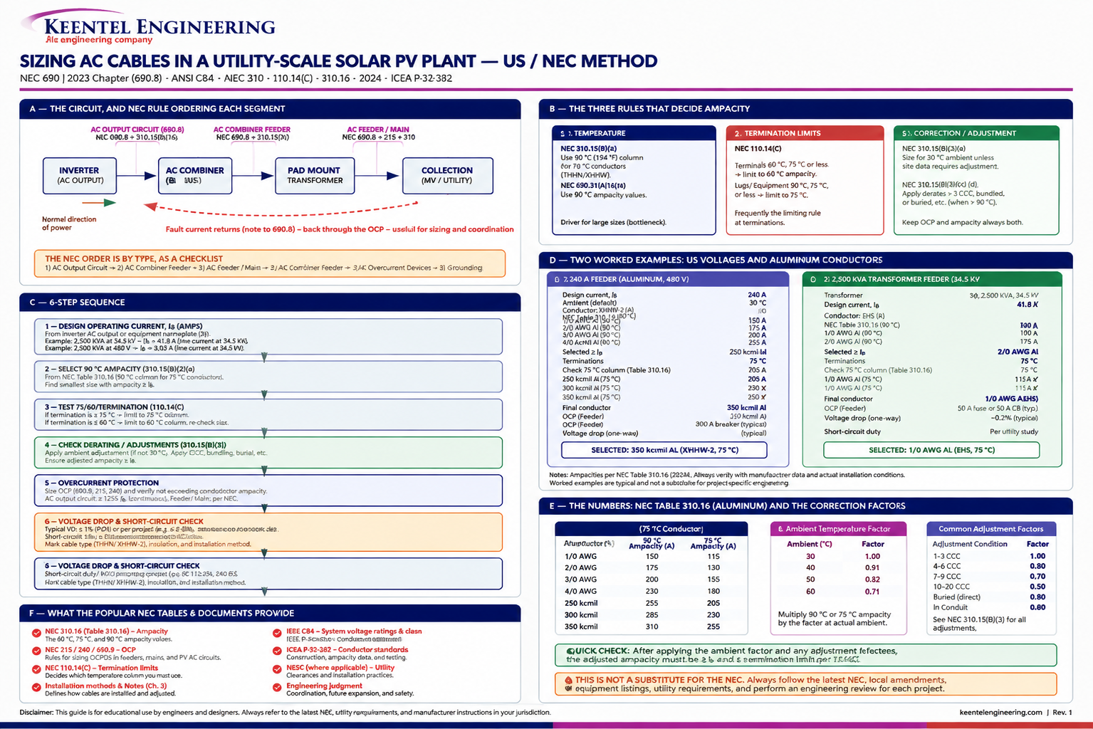
Figure 1, on the following page, summarizes the whole method: the circuit and which rule governs each segment, the three ampacity rules, the eight-step sequence, both worked examples, the NEC tables, and the errors to avoid.
FIGURE 1 — AC cable sizing for utility-scale solar PV, US / NEC method:
circuit segments, the three ampacity rules, sizing sequence, worked examples and tables
9. Nine things worth correcting in the popular guides
1. IS 10262 is a concrete standard. The reference list cites "IS 10262" among the derating factor standards. *IS 10262 is the Bureau of Indian Standards guideline for Concrete Mix Proportioning. It has nothing to do with cables. The Indian cable standards are IS 1554 (PVC), IS 7098 (XLPE), and IS 3961* (current ratings). On a US project none of them apply anyway.
2. The k values are both copper. "115 for Cu, 143 for Al" — 115 is copper PVC, 143 is copper XLPE, aluminium XLPE is 94. Correcting the worked example from k = 115 to the appropriate XLPE value moves the answer from 217 mm² to 175 mm².
3. The derating product is 0.566, not 0.60.
4. Installation method is not a derating factor. It selects the table.
5. Soil thermal resistivity does not apply to a cable in a tray.
6. The 125% continuous-duty multiplier is missing. NEC 690.8(B)(1). This is the largest single omission for a US reader.
7. Terminal temperature limitation is missing. NEC 110.14(C). Reading 90 °C ampacity straight to a 75 °C lug is the most common ampacity error in US practice, and it is invisible until the thermal scan.
8. Design current should come off the nameplate. NEC 690.8(A)(3). And the PF = 1.0 assumption hides the reactive-power obligation most US plants carry.
9. Voltage drop is not a US code check. It is an informational note. Which means the real target is not 1.5% — it is whatever the 25-year loss economics and the inverter operating window justify.
What the graphic gets right, and should get credit for: the four-check framework in the correct order, the full voltage drop formula including reactance, the reminder that ampacity tables are reference-only and manufacturer data governs, and the closing line — good cable sizing is about safety, efficiency, reliability and economy, not just current rating. That is exactly right, and it is the part most engineers skip.
10. Design checks that catch real problems
Conductor material. US utility-scale PV AC collection is overwhelmingly aluminum, not copper. Aluminum is roughly twice as conductive per pound, and at commodity ratios near 4:1 the cost case is not close. AA-8000 series compact-stranded aluminum has been the code-recognized standard since 1972. A copper-only worked example is not representative of how these plants are actually built.
Conductor listing voltage
Most building wire is listed to 600 V. At 630, 660 or 690 V inverter output — all common on 1500 Vdc central inverters — you are above that and need conductors and terminations listed for 1000 V. Note that the NEC's low-voltage boundary moved from 600 V to 1000 V ac / 1500 V dc across the 2014–2017 cycles, and in the 2023 NEC the over-1000 V equipment rules live in the new Article 495. So 690 V does not put you into the medium-voltage chapters — but it does put you outside standard 600 V-listed wire. These are two different constraints and they are frequently conflated.
Article 691 applicability. NEC Article 691, "Large-Scale Photovoltaic (PV) Electric Supply Stations," applies to facilities with a generating capacity of not less than 5,000 kW and not under exclusive utility control. Generating capacity here is read as the sum of inverter continuous AC output at 40 °C, not DC nameplate. Above that threshold, engineered designs stamped by a licensed PE can substitute for certain prescriptive requirements — which changes what you have to prove and to whom.
Medium-voltage collector is a different article. The 34.5 kV collector system is governed by Article 315 in the 2023 NEC (Article 311 in 2020), with its own ampacity tables and its own 40 °C-based correction table. Do not carry Table 310.16 or Table 310.15(B)(1) into the collector design.
Conductor type on the AC side. XHHW-2 aluminum is the workhorse — 90 °C wet and dry, UL 44, tray-rated at 1/0 AWG and larger. PV Wire and USE-2 are DC-side conductors under NEC 690.31(C); they do not belong on an AC circuit.
Terminations and torque
Aluminum terminations require listed connectors, an oxide-inhibiting compound where specified by the listing, and calibrated torque per 110.14(D). More aluminum conductor failures trace to the termination than to the conductor.
11. Anonymized case studies
The following are anonymized and composited from typical engagements. Figures are representative of the scenarios described and have been rounded and adjusted; they do not identify any specific client or facility.
Case Study 1 — Desert Southwest, 200 MWac: the 30 °C assumption
Situation. An EPC submitted the AC cable schedule for a 200 MWac single-axis-tracker project in southern Arizona. Conductor sizes had been carried over from a prior project of similar block size in the upper Midwest.
What the analysis found
Every inverter output circuit had been sized against Table 310.16 with no ambient correction applied. The 30 °C table basis had been treated as the site condition. Recorded design ambient at the site was 45 °C in the conduit environment, and above-grade conduit in direct sun runs hotter still.
Applying Table 310.15(B)(1) at the 41–45 °C band — a 0.87 factor on the 90 °C column — moved a substantial fraction of the blocks below their required post-derating ampacity. Roughly a third of the AC circuits needed one size up. The conductors would not have failed immediately; they would have run continuously above their rated insulation temperature every summer afternoon, aging the insulation on a curve nobody was tracking.
What was done
The schedule was rebuilt with the correct ambient band, and the design ambient was pinned in the basis of design so it could not be silently inherited again. Circuits were reviewed for the 110.14(C) ceiling at the same time, which caught a separate set of blocks where the 90 °C column had been used at 75 °C lugs. Conductor cost rose about 4% on the AC scope. The change was made in design, before procurement.
Engineering takeaway
An ampacity table is a statement about a thermal environment, not about a conductor. A conductor schedule that travels between climates without its ambient assumption travelling with it is a latent defect.
Case Study 2 — Northeast, 20 MWac: the 90 °C conductor at the 75 °C lug
Situation. A 20 MWac project reached AHJ review with a complete, internally consistent AC design. The inspector flagged the inverter output conductors.
What the analysis found
The designer had specified XHHW-2 aluminum and sized every circuit from the 90 °C column of Table 310.16 — correctly noting that XHHW-2 is a 90 °C wet-and-dry conductor. But all the AC combiner breakers, inverter terminals and switchgear lugs were listed for 75 °C terminations. Under NEC 110.14(C)(1)(b), circuits over 100 A must be sized from the 75 °C column.
The gap between the two columns is roughly 13% at these sizes — a 750 kcmil aluminum conductor is 435 A at 90 °C and 385 A at 75 °C. Across the plant, that put a meaningful number of circuits one size undersized against the termination limit.
What was done
The circuits were resized against the 75 °C column, with the 90 °C column retained only as the derating basis. Because conductors were upsized for a code requirement under 110.14(C) rather than for voltage drop, 250.122(B) did not require the EGCs to be increased proportionally — a distinction worth several thousand dollars of copper on a plant this size, and one that is frequently applied incorrectly in the conservative direction.
Outcome
The design cleared review on resubmittal. Because the issue was caught before the conductors were pulled, the cost was engineering hours rather than a re-pull.
Engineering takeaway
The conductor's temperature rating and the circuit's usable ampacity are two different things, and the equipment decides which one you get. If you cannot name the termination temperature rating of every device on a circuit, you cannot yet state its ampacity.
Case Study 3 — ERCOT, 150 MWac: sized in kilowatts, operated in kilovolt-amperes
Situation. A 150 MWac project completed detailed design with the AC collection sized from block real power at unity power factor. Late in the process the interconnection agreement was finalized, requiring the plant to maintain 0.95 leading to 0.95 lagging power factor at the point of interconnection across its operating range.
What the analysis found
The design current for every inverter output circuit had been computed as P / (√3 × V × 1.0). Meeting a 0.95 power factor obligation at full real power output requires the inverters to be sized and operated on kVA, not kW — which raised continuous output current by a factor of 1/0.95, or 5.3%, above the value the cable schedule had been built on.
On its own, 5.3% is inside most conductors' margin. Stacked on top of the 125% continuous multiplier and a summer ambient correction, it pushed a set of circuits past their limit — and it also degraded voltage drop, because the reactance term that vanishes at unity power factor becomes significant at 0.95. On the longest runs, calculated drop went from about 1.2% to about 1.5%, tightening the inverter's AC operating window exactly when it was being asked to produce reactive power.
What was done
Design current was re-established from inverter nameplate continuous output current, per NEC 690.8(A)(3), rather than from a power calculation. Voltage drop was recomputed with the full R cos φ + X sin φ expression at 0.95 PF. Circuits on the longest runs were upsized one size — and because that upsize was for voltage drop rather than for derating, 250.122(B) did require the EGCs to be increased proportionally to circular mil area.
Outcome
The revision touched approximately 15% of the AC circuits and was absorbed in design. The reactive-power obligation was verified against the corrected operating window before the interconnection studies were finalized.
Engineering takeaway
An inverter is a kVA machine, and the interconnection agreement decides how much of that kVA is real power. Sizing conductors from kW at unity power factor builds a plant that is correct only on the days it is not asked to support voltage.
12. Frequently asked questions
Q: What is the single most common AC cable sizing mistake on a US PV project?
Applying 90 °C ampacity at a 75 °C termination. NEC 110.14(C) caps you at the termination rating, and the 90 °C column is only a derating basis. It passes design review because the number came from a real NEC table — just the wrong column for the purpose. It shows up later as hot lugs on a thermal scan. The close second is omitting the 125% continuous-duty multiplier in 690.8(B)(1).
Q: Why 125%? My conductor is rated for its ampacity continuously.
Ampacity tables are built on assumptions about duty and thermal environment that a PV plant violates: full output for six to eight hours, every clear day, for 25 years. The 125% factor is the NEC's continuous-load allowance, and 690.8(B)(1) applies it before derating specifically so that the derating stack cannot erode it.
Q: Should I use copper or aluminum?
Aluminum, for essentially all utility-scale AC collection. It is about half the cost per unit of conductance. You will need roughly one to two sizes larger for the same ampacity and a slightly larger conduit, and both are cheaper than the copper. Use copper where terminations, space constraints, or a specific listing require it.
Q: What voltage drop should I design to?
There is no NEC limit — the 3%/5% figures are informational notes and unenforceable. Design to two real constraints: keep the inverter inside its AC operating window at full output while meeting the plant's reactive-power obligation, and keep total AC cabling loss near 1%. Then check whether upsizing one more size pays for itself over the plant life. Often it does.
Q: Do I derate for cable tray, or for conduit fill, or both?
One or the other, never both. In tray, NEC 392.80 governs: multiconductor cables use Table 310.16 with adjustment only for cables containing more than three current-carrying conductors within a single cable; single conductors use Table 310.17 free-air ampacity with a 75% factor at 600 kcmil and above, or 65% for 1/0 through 500 kcmil. In conduit, 310.15(C)(1) governs. Stacking both is double-counting.
Q: My inverter is 690 V AC. Is that "medium voltage" under the NEC?
No. The NEC's low-voltage boundary is 1000 V ac, not 600 V. But 690 V is above the 600 V listing of most building wire, so you need conductors, terminations, and equipment listed for 1000 V. The code chapter is unchanged; the product listing is not.
Q: How much fault current does the inverter contribute?
Very little. A grid-following inverter is a current-limited power-electronic source, typically 1.2–1.5 per unit of its rated output; grid-forming inverters reach 2–3 p.u. The fault current your conductor has to survive comes from the utility, backfeeding through the step-up transformer. Take it from the system short-circuit study.
Q: What clearing time should I use for the short-circuit check?
The actual total clearing time for the specific protective device that will clear that fault — relay operating time plus breaker interrupting time. Not a round number. Required conductor area scales with √t, so the difference between 0.2 s and 1.0 s is a factor of 2.2 in required area.
Q: The ICEA formula and the IEC adiabatic formula give different answers. Which is right?
They should agree within a few percent, because they are the same physics. If they do not, check your constants: the IEC k for aluminium XLPE is 94, not 143; the ICEA aluminum constants are 0.0125 and 228. And check units — ICEA uses circular mils, IEC uses mm² (1 mm² = 1,973.5 cmil).
Q: When do I have to upsize the equipment grounding conductor?
Per 250.122(B), when you upsize ungrounded conductors for any reason other than ambient or fill derating under 310.15(B)/(C) — most commonly voltage drop. The increase is proportional to circular mil area, not to AWG size or ampacity.
Q: Does Article 691 apply to my project?
If the generating capacity is not less than 5,000 kW and the facility is not under exclusive utility control, yes. Generating capacity is the sum of inverter continuous AC output at 40 °C. Below that threshold you are in Articles 690 and 705 only.
Q: What NEC edition should I cite?
Cite the edition adopted in your jurisdiction, which is frequently not the newest. The 2026 NEC is published, the 2023 is the most widely adopted, and many states are still on 2020 or 2017. This matters for PV specifically because 690.8(A) was restructured in 2026 and Article 310 was renumbered in 2020. Always pair the section number with the edition year.
Q: Can I just use the ampacity table from the cable manufacturer?
Use it to check the manufacturer's own ratings and construction. But the ampacity you design to must come from the NEC tables with NEC correction and adjustment factors, limited by NEC 110.14(C). A manufacturer table that gives you a higher number is describing the cable, not the installation.
13. Standards reference
| Standard / section | Scope |
|---|---|
| NEC 690.8 | PV circuit sizing and current — 690.8(A)(3) inverter output current (2017–2023); 690.8(A)(1)(c) in 2026 |
| NEC 690.8(B)(1) / (B)(2) | 125% before derating; 100% after derating |
| NEC 110.14(C) | Temperature limitations at terminations — the 60 °C / 75 °C ceiling |
| NEC Table 310.16 | Ampacity, ≤3 current-carrying conductors in raceway, cable or earth, 30 °C base |
| NEC Table 310.17 | Ampacity, single insulated conductors in free air |
| NEC Table 310.15(B)(1) | Ambient correction for the 30 °C-based tables |
| NEC Table 310.15(B)(2) | Ambient correction for the 40 °C-based tables |
| NEC 310.15(C)(1) | Adjustment for more than three current-carrying conductors |
| NEC 310.10(G) | Conductors in parallel |
| NEC 392.80 | Ampacity of conductors in cable tray |
| NEC 240.4(B) / 240.4(C) | Next-size-up rule (≤800 A) and the over-800 A rule |
| NEC 250.122 / 250.122(B) | Equipment grounding conductor sizing and proportional upsizing |
| NEC Article 315 | Medium-voltage conductors and cable (2023; Article 311 in 2020) |
| NEC Article 495 | Equipment over 1000 V ac / 1500 V dc (2023; replaced Article 490) |
| NEC Article 691 | Large-scale PV electric supply stations, ≥5000 kW |
| NEC Article 705 | Interconnected electric power production sources |
| NEC Chapter 9, Table 9 | AC resistance and reactance for voltage drop |
| ICEA P-32-382 | Short-circuit withstand of insulated conductors |
| UL 44 / UL 83 | Thermoset (XHHW-2, RHW-2) and thermoplastic (THWN-2) conductor listings |
| IEEE PES-TR67.r1 | Inverter fault-current behavior and IEEE 1547 impacts |
| IEC 60364-4-43, Table 43A | k values for the adiabatic short-circuit equation (international projects) |
Closing
The four-check framework in that infographic is sound, and anyone using it is ahead of an engineer who sizes conductors by ampacity alone. The problem is not the method. The problem is that the method was assembled from one code family and is being applied in another, and the two do not disagree politely — they disagree by 25% on the continuous-duty multiplier and by 13% at the lug.
On a US utility-scale PV project the conductor schedule is one of the largest single material line items on the AC scope, and it is also one of the least forgiving. Undersize it and you get insulation aging you cannot see and losses you pay for every day for 25 years. Oversize it uniformly and you have spent money that had better returns elsewhere in the plant.
At Keentel Engineering, AC and DC collection design, cable schedules, short-circuit and arc-flash studies, and POI interconnection engineering are delivered together, because they are the same problem viewed from different angles. If you have a cable schedule to review, an ambient assumption you inherited, or an interconnection requirement that just changed your design current, we would be glad to look at it.
KEENTEL ENGINEERING
Tampa, FL · Austin, TX · Sacramento, CA · Baltimore, MD
keentelengineering.com · contact@keentelengineering.com · 813-389-7871
Engineering note: NEC section numbers are given for the 2023 edition unless otherwise stated, with 2020 and 2026 differences flagged where they exist. Confirm against the edition adopted in your jurisdiction. Ampacity values are from NEC Table 310.16 and are reproduced for illustration; design from the code book. Nothing here substitutes for a project-specific engineering design.

About the Author:
Sandip "Sonny" R. Patel, P.E.
IEEE Senior Member · Founder & CEO, Keentel Engineering
In 1995, Sonny Patel earned his Electrical Engineering degree from the University of Illinois. But degrees don't build legacies — action does.
For three decades, he has worked the power industry from every side of the table: 16 years as a utility engineer at Exelon/Commonwealth Edison; generation leadership across hydroelectric, industrial steam turbine, and a 9 GW renewable fleet; NERC Regional Entity Senior Compliance Engineer and Audit Team Lead, auditing some of the nation's largest utilities; and testing and commissioning lead on equipment up to 765 kV — the very top of the North American grid.Utility. Generator. Regulator. Consultant. Few engineers have seen all four seats. Fewer still have sat in them.
His experience spans nuclear, hydro, conventional generation, renewables, oil and gas, mining — and today's data centers, where he is authoring a three-book series on data center design. He is a Licensed Professional Engineer in six states and a Licensed Electrical Contractor in Florida (Unlimited EC) — he doesn't just design the work; he's qualified to stand behind its execution.Today, as Founder and CEO of Keentel Engineering, Sonny leads a nationwide team of engineers delivering substation design, power system studies, NERC compliance, and commissioning — done right, coast to coast.Three decades. Every side of the table. One standard: accountable engineering.
Services

Let's Discuss Your Project
Let's book a call to discuss your electrical engineering project that we can help you with.
About the Author:
Sandip "Sonny" R. Patel, P.E.
IEEE Senior Member · Founder & CEO, Keentel Engineering
In 1995, Sonny Patel earned his Electrical Engineering degree from the University of Illinois. But degrees don't build legacies — action does.
For three decades, he has worked the power industry from every side of the table: 16 years as a utility engineer at Exelon/Commonwealth Edison; generation leadership across hydroelectric, industrial steam turbine, and a 9 GW renewable fleet; NERC Regional Entity Senior Compliance Engineer and Audit Team Lead, auditing some of the nation's largest utilities; and testing and commissioning lead on equipment up to 765 kV — the very top of the North American grid.
Utility. Generator. Regulator. Consultant. Few engineers have seen all four seats. Fewer still have sat in them.
His experience spans nuclear, hydro, conventional generation, renewables, oil and gas, mining — and today's data centers, where he is authoring a three-book series on data center design. He is a Licensed Professional Engineer in six states and a Licensed Electrical Contractor in Florida (Unlimited EC) — he doesn't just design the work; he's qualified to stand behind its execution.
Today, as Founder and CEO of Keentel Engineering, Sonny leads a nationwide team of engineers delivering substation design, power system studies, NERC compliance, and commissioning — done right, coast to coast.Three decades. Every side of the table. One standard: accountable engineering.
Leave a Comment
Thank you for contacting us.
We will get back to you as soon as possible.
We will get back to you as soon as possible.
Oops, there was an error sending your message.
Please try again later.
Please try again later.
Related Posts

By SANDIP R PATEL
•
October 3, 2026
Engineering guide to PRC-028 disturbance recording, PRC-029 ride-through and PRC-030 event detection for inverter-based resources.

By SANDIP R PATEL
•
October 3, 2026
A practical guide to SSO classification, SSR, PEDI, Wind-SSCI, EMT analysis, mitigation and protection based on CIGRE TB 909.

By SANDIP R PATEL
•
October 3, 2026
Learn ERCOT generator testing for PFR, MOD-025 and MOD-026/027, including staged tests, capability verification, dynamic models and field testing.

By SANDIP R PATEL
•
October 3, 2026
Learn how PV string I-V curve testing identifies hidden solar performance losses, including soiling, shading, mismatch, degradation, and wiring faults.

By SANDIP R PATEL
•
October 3, 2026
Learn how active harmonic filters work, how to size AHF systems, reduce VFD harmonics, calculate losses, and meet IEEE 519 TDD limits at the PCC.
By SANDIP R PATEL
•
October 3, 2026
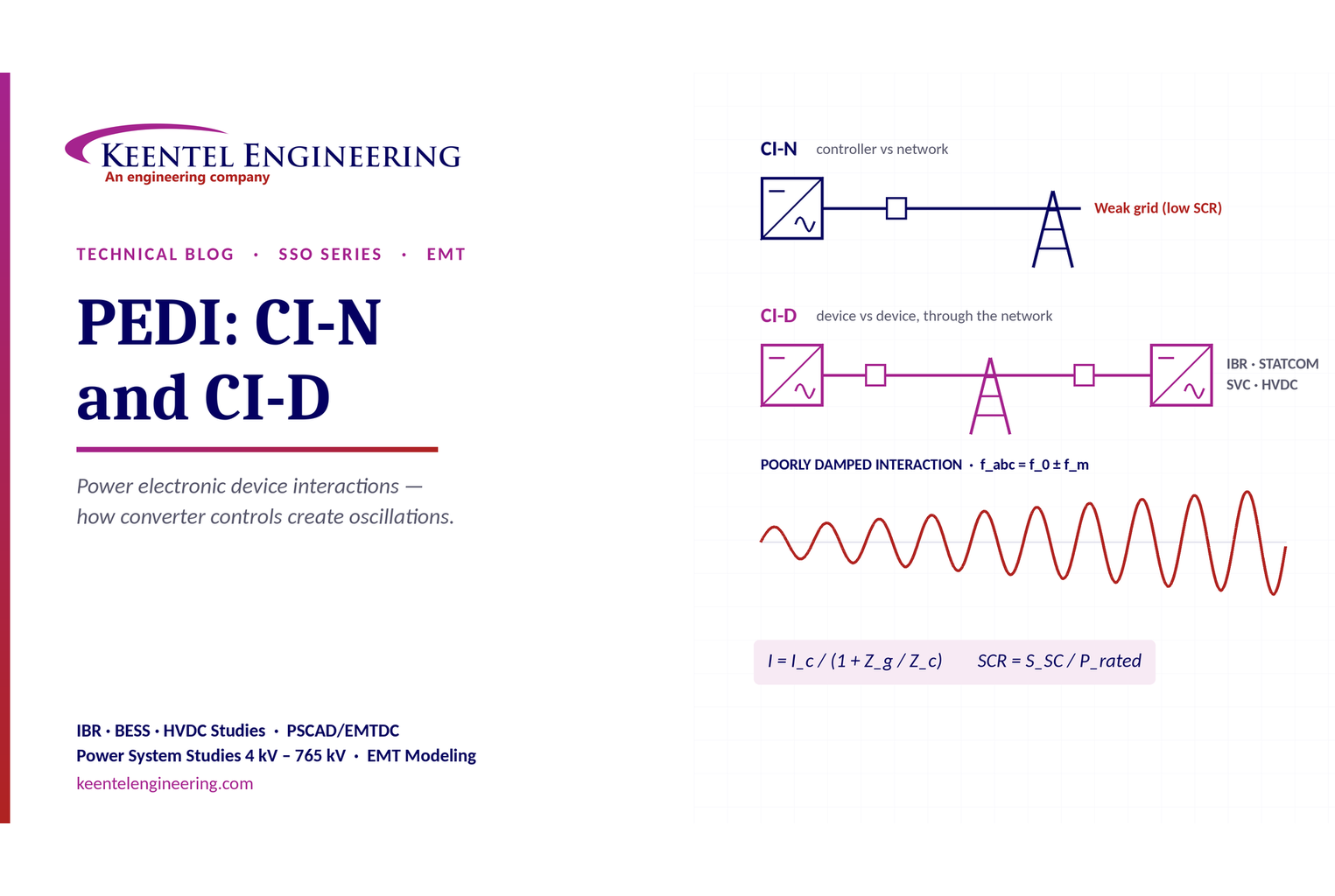
Learn power electronic device interactions (PEDI), including CI-N and CI-D, weak-grid stability, SCR, EMT studies, impedance analysis and mitigation for IBRs.
By SANDIP R PATEL
•
October 3, 2026
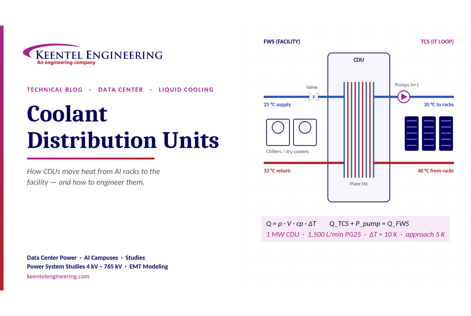
Learn how data center coolant distribution units (CDUs) work, including FWS and TCS loops, heat transfer, sizing, redundancy and liquid cooling for AI data centers.
By SANDIP R PATEL
•
October 3, 2026
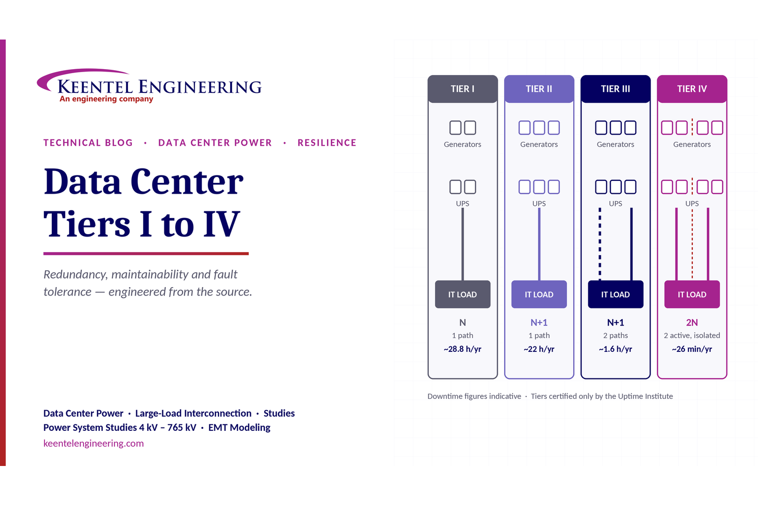
Compare Data Center Tiers I–IV, including redundancy, uptime, Tier III concurrent maintainability, Tier IV fault tolerance, UPS, generators and power design.

By SANDIP R PATEL
•
October 3, 2026
Learn how BESS supports grid stability through fast frequency response, voltage support, oscillation damping, black start, grid-forming controls and EMT studies.





