
A Coordinated Electric System Interconnection Review—the utility’s deep-dive on technical and cost impacts of your project.
Challenge: Frequent false tripping using conventional electromechanical relays
Solution: SEL-487E integration with multi-terminal differential protection and dynamic inrush restraint
Result: 90% reduction in false trips, saving over $250,000 in downtime
ERCOT enforces all of the above through simulation, which means your model is your compliance case. The bar is now high:
- Whole-facility scope. The model must represent everything the IT load, the UPS and power conversion, the cooling plant, the protection and control systems in formats compatible with ERCOT's study platforms (PSS/E, PSCAD, TSAT).
- Real control loops, not approximations. Generic textbook representations are unacceptable. The model must capture the actual inner control behavior of your power electronics.
- Hardware-validated converter models. For electronic loads, the PSCAD model must be benchmarked against actual hardware testing including voltage ride-through and subsynchronous response. A model assembled from standard PSCAD library blocks fails by definition, because a generic block has never been tested against your vendor's hardware. The good news: validation is a hardware-type test, so results for a given converter product are reusable across every facility that uses it.
- Format migration. Facilities that previously submitted the older composite load model (CMLD) format must transition to EPRI's PERC1 format.
- Three checkpoints. Models are reviewed before the stability study begins (no model, no study), before each quarterly stability assessment, and for electronic loads one final time before energization, when you must submit as-built models with a documented comparison against the previously studied data and a sworn attestation that the model matches actual field settings. ERCOT's review takes 10 business days, extendable by 20 put it on your critical path.
- A living obligation. Change your technology, controls, or relay settings in a way that affects ride-through including converting a crypto mining site to an AI data center — and you've triggered a new interconnection study, even if your megawatts don't change.
| Parameter | Detail |
|---|---|
| System | 230 kV / 138 kV transmission corridors, wind and wet-snow icing exposure |
| Data basis | 15 years of minute-resolution forced-outage records + regional weather observations |
| Core methods | Event grouping, MVA performance curves, time-to-95%-restore, area outage rate curves, fragility modeling, rerun-history benefits, exceedance and log-domain risk metrics |
| Headline result | ≈85% of maximum resilience benefit at 60% of original capital; worst-event restoration window cut from 11 days to 5 in rerun-history terms |
| Decision supported | Capital portfolio selection; resilience plan filing; post-investment verification framework |
| System / Topic | Governing Standard(s) | What It Controls |
|---|---|---|
| Overall plant electrical distribution | IEEE 141 (Red Book); IEEE 666 | Distribution architecture, voltage selection, design of generating station auxiliary service systems |
| Power system studies | IEEE 399 (Brown Book); IEEE 551 | Load flow, symmetrical/asymmetrical short circuit, motor starting methodologies down to the lowest LV panelboard |
| Protection & coordination | IEEE 242 (Buff Book); IEEE 3004.5; IEEE C37 series | Generator relaying (21, 59N, 87G), time-current coordination, selective clearing between LV and MV tiers |
| GSU / UAT / SST transformers | IEEE C57.12.00 and C57 family | Transformer ratings, impedance, testing, loading |
| HV switchyard breakers | IEEE C37.06 | AC high-voltage circuit breaker preferred ratings |
| MV switchgear (13.8 kV) | IEEE C37.20.2; IEEE C37.20.7 | Metal-clad construction, compartmentalization, vacuum breakers; arc-resistant design with plenum venting |
| MV cable | UL 1072; ICEA S-93-639 (NEMA WC 74) | Type MV-105 shielded cable, 133% insulation level for HRG systems |
| LV switchgear (480 V) | IEEE C37.13; UL 1558 | Metal-enclosed LV power circuit breaker switchgear to 635 V, draw-out ACBs with electronic trip units |
| Motor control centers | UL 845; NEMA ICS 18 | LV-MCC construction, MCCB/MCP protection for motors under ~200 HP |
| Motors | NEMA MG-1 | Motor performance, starting characteristics, service factors |
| DC & battery systems | IEEE 485; IEEE 946 | Lead-acid battery sizing (125/250 VDC), DC auxiliary system design |
| Grounding | IEEE 80; IEEE 142 (Green Book) | Ground grid step/touch potential limits; system grounding including high-resistance grounding |
| Lightning protection | IEEE 998 | Direct-stroke shielding of switchyard and outdoor generator structures |
| Arc flash & electrical safety | IEEE 1584; NFPA 70E | Incident energy calculation; worker safety boundaries and PPE |
| Fire protection | NFPA 850 | Fire protection and risk management for combustion turbine generating plants |
| Installation code | NEC (NFPA 70); NESC | Wiring methods inside the plant fence; overhead/outdoor clearances at the switchyard |
| Interconnection & compliance | FERC LGIP; NERC MOD-025/026/027, PRC-019/024/029, FAC-008 | Interconnection process, model validation, protection/ride-through coordination, facility ratings |
| IFC / Construction Deliverable | Purpose |
|---|---|
| Stamped IFC packages | Legal basis for construction; P.E. responsible charge |
| Final relay settings & TCCs | Protection as-installed matches the coordination study |
| Calculation archive | Owner records; NERC audit evidence trail |
| Commissioning procedures | Safe, sequenced energization; MOD field testing |
| Construction support | RFIs, field changes, FAT/SAT witness |
| As-builts & model handoff | Operating baseline; future study currency |
| Metric | Outcome |
|---|---|
| Defects found pre-occupancy | Three topology defects and one settings-mismatch family corrected before load migration; the shared-switchboard defect alone would have invalidated the concurrently-maintainable claim on day one |
| IST findings | Fourteen additional discrepancies surfaced under scenario testing (control logic, alarm mapping, one generator sequencing fault) — all closed before handover instead of during operations |
| Black-building test | Passed on second execution; the first attempt exposed the generator sequencing fault under true block load, exactly the failure the compressed plan would never have found |
| Handover quality | Operations team certified on the actual failure scenarios; corrected EOPs and settings documentation delivered as controlled documents |
| Business outcome | Occupancy proceeded three weeks behind the original date — against an independent estimate that the uncorrected sequencing fault carried a high probability of a full facility outage within the first year |
Part 2 — Frequently Asked Questions: Large Load Interconnection
An electric grid must remain in continuous balance — generation onto the grid must equal consumption from it at every instant. PJM achieves this balance, and prices it, through a layered market architecture. Each layer operates on a different time horizon, and each one touches project economics differently.
| Domain | Key Standards / Codes | What They Govern |
|---|---|---|
| Fire safety | NFPA 855; UL 9540 / UL 9540A | Installation requirements, separation, gas management; system safety listing and thermal-runaway fire testing |
| Grid interconnection | IEEE 1547 (distribution); IEEE 2800 (transmission IBRs) | Ride-through, reactive capability, power quality, and performance at the point of interconnection |
| Power quality | IEEE 519 | Harmonic distortion limits at the PCC |
| Protection & grounding | IEEE 80 / 81 / 142; C37 series | Grounding system design and testing; protective relaying |
| Reliability compliance | NERC standards (incl. PRC ride-through requirements) | Registered-entity obligations for grid-connected storage |
The Nine Types of Earthing Every Engineer Should Understand
Aug 14, 2026 | Blog
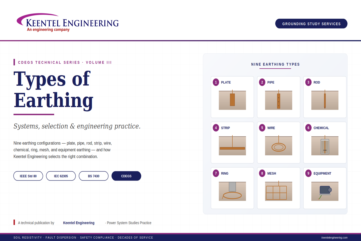
Ask five electrical engineers what "earthing" means, and you will get five answers — all technically correct, all incomplete. Earthing is a family of engineering techniques, each with a specific physical mechanism, application domain, and set of trade-offs. Choosing the wrong type for a given site is one of the most common — and most expensive — root causes of grounding-related failures, whether that failure manifests as protection relays that will not operate, equipment damaged by transient overvoltage, personnel exposed to unsafe touch voltages, or expensive rework at commissioning.
This article — Volume III of the Keentel Engineering CDEGS technical series — walks through the nine principal earthing types used in modern electrical installations. For each, we explain the physical mechanism, the applications where it excels, the applications where it is a poor fit, and how it appears in Keentel Engineering's grounding study practice.
Why Nine Types, Not One?
If a single earthing method worked well across all soil conditions, all fault current levels, all site geometries, and all installation constraints, we would use it universally. But the physics does not cooperate. Soil resistivity varies from under 20 Ω·m in wet clay to over 5,000 Ω·m in dry rocky terrain. Fault currents range from tens of amperes on isolated LV systems to hundreds of kiloamperes on major transmission substations. Some installations occupy 380 hectares; others are confined to a rooftop equipment cabinet. Each combination demands an earthing solution matched to its specific electrical and site constraints.
The nine types below are not competing alternatives — they are complementary tools. Most real installations use several of them in combination. A utility substation, for example, may use mesh earthing for the main yard, rod earthing at surge arrester bases, ring earthing around perimeter fence footings, and equipment earthing to bond every transformer tank and enclosure back to the mesh. Understanding each type in isolation is the prerequisite for combining them intelligently.
The engineering principle underlying all earthing types
Every earthing installation performs the same fundamental function: it provides a low-impedance electrical path between metallic equipment (or a system reference point) and the general mass of earth, so that fault currents disperse safely and touch and step voltages remain within human-tolerable limits. The nine types differ in how they achieve that path — vertically, horizontally, in poor soil, in restricted space, with or without chemical enhancement — but the fundamental engineering goal is the same.
1. Plate Earthing
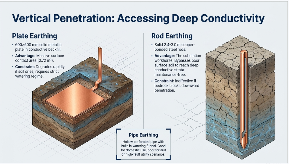
Plate earthing uses a solid metallic plate — typically copper or galvanized iron, 600 × 600 mm and 3 to 6 mm thick — buried vertically in a pit filled with alternating layers of charcoal and salt (traditional practice) or conductive backfill (modern practice). An earth conductor is bolted to the plate and rises to the surface for connection to the earthing terminal.
The plate's advantage is surface area. A 600 × 600 mm plate provides roughly 0.72 m² of contact surface with the surrounding backfill — significantly more than a comparable-length rod. This surface area translates directly into low earth resistance in reasonable soils.
Where it excels
Plate earthing is well suited to distribution transformer earthing, industrial equipment installations where a dedicated earth pit is provided, and any application where the client has committed to a maintainable earth pit with periodic re-watering.
Where it struggles
Plate earthing is not effective in rocky terrain where the pit cannot be excavated to adequate depth, in very dry soils where the plate-to-soil contact degrades rapidly, or in installations where periodic maintenance (watering the pit, checking the connection at the earth conductor) will not be performed. The plate's surface area is only useful if intimate contact with moist conductive material is maintained; that contact deteriorates over time in most soil conditions.
2. Pipe Earthing
Pipe earthing uses a hollow perforated pipe — typically galvanized iron or copper, 38 to 100 mm diameter, 2.5 to 3.0 m long — driven vertically into the ground. The perforations along the pipe body allow water infiltration to maintain conductive contact with the surrounding soil. A funnel and cover at the top permit periodic watering to keep the soil moist and conductive.
Pipe earthing is the most common earthing type in South Asian and Middle Eastern practice, largely because it combines reasonable performance with straightforward installation and the possibility of ongoing maintenance.
Where it excels
Pipe earthing works well in moderate soil conditions where periodic watering is feasible, in domestic and commercial installations where a maintenance regime is realistic, and in agricultural and semi-urban environments where surface access to the earth pit is easily arranged.
Where it struggles
In arid environments without a watering regime, pipe earthing resistance can drift upward significantly within months. It is also unsuited to very high fault current applications, where the pipe's current-carrying capacity — and the peak transient voltage at the injection point — can be inadequate. For substation and transmission applications, other types dominate.
3. Rod Earthing
Rod earthing uses a solid vertical rod — typically copper-bonded steel, 2.4 to 3.0 m long, 16 to 19 mm diameter — driven directly into the ground with no surrounding pit or backfill. Multiple rods are commonly connected in parallel to reduce overall resistance, spaced at least their own length apart to avoid mutual interference.
Rod earthing is the workhorse of substation grounding worldwide. It is simple, robust, requires no maintenance beyond periodic bonding-connection inspection, and — critically — allows deep electrodes to reach conductive strata below poor surface soil.
Where it excels
Rod earthing is standard for substation grounding grids (used alongside horizontal mesh), telecommunications infrastructure, industrial equipment earthing where deep conductive layers exist below the surface, and any installation demanding low maintenance over decades.
Where it struggles
In rocky terrain where rods cannot be driven, in shallow bedrock sites, or in installations requiring extremely low resistance (below 0.5 Ω) where the number of rods becomes uneconomic compared to a horizontal mesh, rod earthing alone is often inadequate. The solution is usually rod earthing combined with mesh earthing (see below).
4. Strip Earthing
Strip earthing uses a horizontal metallic strip or tape conductor — typically 25 × 4 mm copper or galvanized steel — laid in a shallow trench (0.5 to 1.0 m deep) filled with fine soil or conductive backfill. The strip extends horizontally over a substantial length (10 m or more) to provide adequate surface contact.
Strip earthing is particularly valuable where vertical earthing is impractical: on rocky sites, above shallow bedrock, in high-resistivity terrain where a single rod would achieve inadequate resistance, and along transmission line routes where a counterpoise conductor is laid parallel to the line.
Where it excels
Strip earthing works in rocky and high-resistivity terrain where rods cannot be driven, along transmission line counterpoise applications, for building perimeter earthing where a trench can be excavated during construction, and in industrial installations where large horizontal trenches for cabling are already required.
Where it struggles
Strip earthing requires substantial linear space and is impractical on constrained-footprint sites. It is also vulnerable to accidental damage from subsequent excavation if not documented and marked, and its performance depends on maintaining trench backfill in reasonable condition — not always guaranteed on active industrial sites.
5. Wire Earthing
Wire earthing uses a bare copper conductor (typically 25 to 70 mm²) coiled or looped horizontally, buried at approximately 0.5 to 1.0 m depth. The loop configuration provides significant surface contact with the soil in a compact footprint. Wire earthing is functionally similar to strip earthing but uses flexible round conductor rather than rigid strip.
Where it excels
Wire earthing is well suited to residential and small commercial installations where a compact earthing footprint is required, to telecommunications equipment on rooftops or in confined spaces, and to portable or temporary installations where re-usability matters.
Where it struggles
Like strip earthing, wire earthing is not suitable for very high fault currents (the conductor's cross-section limits its current-carrying capacity), and its performance in dry soils is limited compared to deep rod or chemical earthing solutions.
6. Chemical Earthing
Chemical earthing enhances a vertical rod or plate by surrounding it with a low-resistivity conductive compound — typically Bentonite (a clay mineral, 2 to 3 Ω·m when hydrated) or a proprietary Ground Enhancement Material (GEM, often 0.1 to 1 Ω·m). The compound is placed in a pit or a purpose-made container around the electrode, dramatically reducing the electrode-to-earth contact resistance.
Chemical earthing is a modern solution for high-resistivity soils, seasonal variation problems, and installations where achieving a low target resistance with conventional electrodes would require impractical numbers of rods or plate quantities.
Where it excels
Chemical earthing works in high-resistivity soils (dry, sandy, rocky), in urban rooftop installations for telecommunications and IT equipment where deep soil access is impossible, in critical facilities (data centers, hospitals, control rooms) demanding low earthing resistance year-round, and in seasonal-variation problem sites.
Where it struggles
Chemical earthing is more expensive per electrode than plain rod or plate earthing. Bentonite requires stable moisture — in drainage-vulnerable sites it can dry out; manufactured GEM products have longer service life but are more expensive. The chemical must be selected for compatibility with the soil chemistry — some proprietary compounds interact adversely with saline or acidic soils. And, like any earthing installation, chemical earthing requires periodic testing to verify continued effectiveness.
7. Ring Earthing
Ring earthing uses a closed circular or rectangular conductor loop buried around the perimeter of a structure — typically a building foundation, a wind turbine tower, a substation transformer plinth, or a communications mast. The ring is bonded to the structure at multiple points and to any local vertical electrodes.
The ring's function is threefold: it provides a large-area distributed electrode surface for dispersing fault current, it produces a near-equipotential zone around the structure to limit touch and step voltages at accessible points, and it provides a robust bonding backbone for lightning down-conductors and equipment earthing risers.
Where it excels
Ring earthing is standard for wind turbine foundations, telecommunications towers, tall building lightning protection systems, transformer plinths, and any structure where personnel access at the base must be safe under fault or lightning conditions.
Where it struggles
Ring earthing alone is rarely adequate for high-fault-duty applications; it is almost always combined with vertical rods or a horizontal mesh to achieve target resistance and current-carrying capacity. The ring's benefit is equipotentialization at the surface, not primary earthing resistance.
8. Mesh Earthing
Mesh earthing — also called grid earthing — uses a rectangular grid of horizontal conductors buried at 0.5 to 1.0 m depth, forming a mesh with typical spacing of 3 to 7 m. Vertical rods are usually added at grid intersections, perimeter corners, and high-current injection points. Mesh earthing is the standard for utility substations, industrial primary substations, and any installation requiring low resistance with controlled touch and step voltages across a defined area.
Volume II of this technical series covered mesh earthing in depth. Its dominance in substation practice is not accidental — no other single earthing type combines low resistance, current-carrying capacity, and controlled surface voltage gradients across a large footprint as effectively.
Where it excels
Mesh earthing is the standard for utility and industrial substations of all voltage classes, large equipment platforms (transformers, switchgear yards), and any installation where personnel work regularly on an energizable surface.
Where it struggles
Mesh earthing requires substantial footprint and is not practical for compact installations. On very small sites (a rooftop cabinet, a residential main earthing point), other types are more appropriate. And on sites with hard bedrock at very shallow depth, mesh installation may require blasting or deep sockets, driving up cost.
9. Equipment Earthing
Equipment earthing is not a separate primary electrode system — it is the bonding of every metallic enclosure, equipment case, structural member, and cable armour to the main earthing system. Its purpose is to ensure that any accessible metallic surface remains at essentially the same potential as the main earth, so that touch voltages remain safe even during faults.
Equipment earthing is universal — every code-compliant electrical installation of any significance includes it. Its design considerations are less about the earthing physics (which is inherited from whichever primary earthing type is used) and more about bonding conductor sizing, connection integrity, and long-term reliability of every bond point.
Where it excels
Equipment earthing is the universal safety backbone of every electrical installation. It works in combination with any of the other eight earthing types, extending their protective function to every accessible metallic surface.
Where it struggles
The failure modes of equipment earthing are almost never the bonding conductors themselves; they are the connection points. Bolted connections corrode, welded connections crack under vibration, and lug crimps deteriorate. The commonest earthing-related incident cause in operational facilities is a single failed bond that was assumed to be continuous. Regular inspection and testing is not optional.
| Type | Typical Application | Key Strength | Key Limitation |
|---|---|---|---|
| 1. Plate | Distribution transformers, LV equipment | Large contact area | Needs maintenance & moist soil |
| 2. Pipe | Domestic, commercial, small industrial | Watering permits maintenance | Poor in arid conditions |
| 3. Rod | Substations, telecoms, industrial | Reaches deep conductive strata | Not effective in shallow rock |
| 4. Strip | Rocky terrain, transmission counterpoise | Works where rods cannot be driven | Requires linear space |
| 5. Wire | Residential, telecom rooftops | Compact footprint | Limited current capacity |
| 6. Chemical | High-resistivity soils, critical loads | Achieves low resistance in poor soil | Higher cost, needs moisture |
| 7. Ring | Towers, wind turbines, building foundations | Equipotentialization around structure | Rarely adequate on its own |
| 8. Mesh | Substations, industrial plant | Low R + safe touch/step voltages | Requires substantial footprint |
| 9. Equipment | Universal safety bonding | Extends earth to every accessible metal | Connection integrity is the failure mode |
How Keentel Engineering Selects the Right Combination
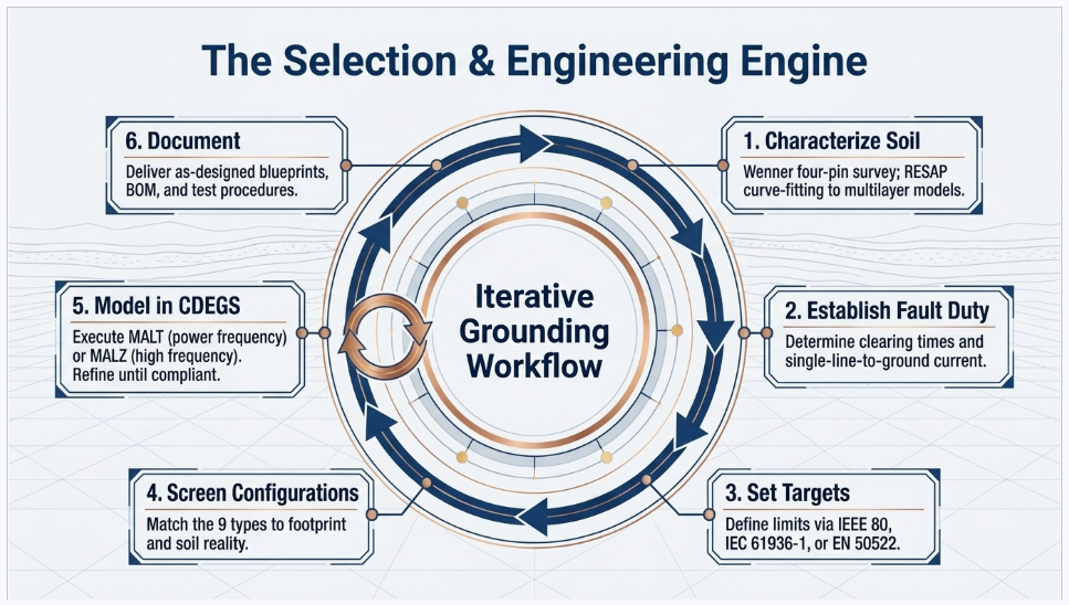
On every grounding study, the earthing type is not chosen from a catalogue — it is derived from the site's soil model, the installation's fault duty, the available footprint, the standards framework, and the client's operational constraints. Our standard analytical workflow is:
- Characterize the soil — Wenner four-pin resistivity survey, RESAP curve-fitting to a two-layer or multilayer model, and identification of any conductive strata that would reward deep electrodes.
- Establish the design fault current and clearing time — from the utility fault-level letter, downstream protection settings, and any embedded generation on the client's network.
- Set the target resistance and touch/step voltage limits — from the applicable standards (IEEE Std 80, IEC 61936-1, EN 50522, AS 2067, or others as jurisdictionally required).
- Screen candidate earthing configurations — for a small building, wire or plate earthing may suffice; for a substation, mesh earthing with rods is the baseline; for a rocky wind turbine site, ring earthing plus chemical-enhanced deep electrodes is often the answer.
- Model the chosen configuration in CDEGS — using RESAP for soil, FCDIST for fault current distribution, and MALT (or MALZ for frequency-dependent analysis) for the grounding computation itself. Iterate until compliance is achieved with margin.
- Document the deliverable — including as-designed drawings, bill of materials, calculation report, sensitivity analysis, and post-installation testing procedure.
The choice of earthing type is not the study's main output; it is one of many outputs, integrated into a complete grounding engineering deliverable that the client can hand to their EPC contractor with confidence.
Keentel Engineering Grounding Study Services
Keentel Engineering provides the full spectrum of grounding study services across utility, industrial, commercial, and renewable-energy sectors:
- Soil resistivity surveys and interpretation — Wenner four-pin surveys, RESAP curve-fitting to two-layer or multilayer soil models, and interpretation reports suitable for downstream design use.
- Substation grounding design — full mesh earthing design with fault current distribution, EPR calculation, touch and step voltage verification, and IEEE Std 80 / IEC 61936-1 / EN 50522 compliance certification.
- Industrial and mining plant earthing — extended earthing systems integrating substation grid, structural steel, process piping, and equipment bonding into a unified plant-wide earthing framework.
- Renewable energy earthing — solar farm tracker-field earthing, wind farm ring-and-rod earthing, and battery storage facility grounding.
- Telecommunications earthing — tower earthing, equipment shelter earthing, and lightning protection integration for cellular, microwave, and broadcast facilities.
- Building and infrastructure earthing — data centers, hospitals, commercial buildings, and critical infrastructure where equipment protection and personnel safety demand low-resistance, well-documented earthing.
- Post-incident investigation and remediation — root cause analysis of earthing-related incidents, and design of corrective measures that address the underlying deficiency.
- Existing installation review and upgrade — assessment of legacy earthing systems against current standards, identification of gaps, and design of cost-effective upgrade paths.
Every study is delivered by CDEGS-competent engineers, documented against the applicable standards, and structured to withstand utility engineering review, regulatory audit, and independent third-party scrutiny. Our practice is built on the conviction that grounding is not a compliance checkbox — it is life-safety infrastructure whose analysis deserves rigor commensurate with the risk it manages.
Case Study 1: Retrofit of a 66/11 kV Utility Distribution Substation with Hybrid Earthing
Client and Project Profile
Client: Confidential utility distribution operator. Asset: Existing 66/11 kV distribution substation, 40-year-old installation, 2 × 15 MVA transformers, upgraded fault duty following network reinforcement (from 8 kA to 15 kA at the 66 kV bus). Scope: Earthing system assessment against current standards, design of upgrade to meet updated fault duty, integration of hybrid earthing (existing mesh + supplementary rod earthing + strip earthing along replaced fence line). Tools: CDEGS — RESAP, FCDIST, MALT, AutoGroundDesign. Standards: IEEE Std 80, IEC 61936-1, and jurisdictional utility grounding code.
Background
The utility had reinforced a section of its 66 kV subtransmission network to accommodate load growth in an adjacent urban area. The reinforcement — comprising a new incoming 66 kV circuit and stronger source contribution from a nearby generating station — raised the design single-line-to-ground fault current at the affected 66/11 kV distribution substation from a historical 8 kA to a new 15 kA. The substation's original grounding grid, installed in the 1980s, had been designed for the 8 kA fault duty and had not been reassessed since.
A routine engineering review flagged the fault-duty change as a potential grounding compliance issue. Keentel Engineering was engaged to assess the existing earthing system against the new fault duty and current standards, and to design an economically defensible upgrade if non-compliance was confirmed.
Engineering Challenge
Three technical realities shaped the challenge:
- The existing grounding grid was documented (record drawings existed), but no as-built survey had been performed since the original installation. Actual buried grid geometry needed physical verification.
- The site was surrounded by mature landscaping and adjacent property boundaries, meaning grid perimeter extension was constrained and any upgrade had to work primarily within the existing footprint.
- The utility's earthing standards had been updated twice in the intervening 40 years, and the substation had not been retrospectively verified against either revision. Both the fault-duty change and the standards drift needed to be assessed.
Approach
Step 1: Site Investigation and Physical Verification
Before any computational work, a physical inspection was conducted. Selective excavation at documented tap points confirmed the buried grid geometry matched the record drawings within acceptable tolerance. A bonding audit checked continuity between the grid, transformer tanks, structural steel, fence, and equipment cases; two bonded points at the fence-line showed elevated resistance (3.8 Ω and 5.2 Ω) attributable to bolt corrosion at the above-ground connection lugs — flagged as immediate remediation regardless of the grid upgrade outcome. Overall grid integrity was confirmed adequate.
Step 2: Soil Resistivity Survey
Wenner four-pin measurements were taken across two traverses with spacings from 1 to 60 m. Apparent resistivity ranged from 68 Ω·m at 1 m spacing to 380 Ω·m at 60 m spacing. RESAP fitted a two-layer soil model: 3.2 m surface layer at 88 Ω·m, deep layer at 620 Ω·m. RMS curve-fit error was 4.1%, within acceptance.
Step 3: FCDIST and Baseline MALT Analysis
FCDIST modelled the new fault duty (15 kA total at 66 kV) accounting for two incoming shielded 66 kV circuits, three outgoing 11 kV distribution feeders, and the utility's reinforced source network. The grid current was calculated at 5.8 kA — 38.7% split factor. MALT analysis of the existing grid at this new fault current returned:
| Parameter | Result | IEEE Std 80 Limit | Status |
|---|---|---|---|
| Grid resistance R_g | 0.82 Ω | As low as practicable | Acceptable |
| Earth potential rise | 4,756 V | N/A | Reference |
| Peak touch voltage E_t (fence corner) |
812 V | 720 V (0.20 s clearing) |
NON-COMPLIANT (12% over) |
| Peak step voltage E_s (perimeter) |
246 V | 2,340 V | Compliant |
The touch voltage exceedance at two fence corners confirmed non-compliance under the new fault duty. An upgrade was required.
Step 4: Hybrid Upgrade Design
Rather than replace the existing grid — which would have been extraordinarily disruptive to operations — a hybrid upgrade was designed combining three earthing types:
- Existing mesh grid retained (Type 8: mesh earthing) — verified to be in adequate physical condition.
- Supplementary rod earthing (Type 3: rod earthing) — eight new 4.5 m copper-bonded steel rods installed at the two non-compliant fence corners and around the two transformer bases, driven to reach the deeper (but more resistive) soil layer for improved current dispersal at the corners.
- Strip earthing along the fence perimeter (Type 4: strip earthing) — a 25 × 4 mm copper strip buried at 0.6 m depth, 1.2 m outside the fence line along all four perimeter sides, bonded to the main grid at eight points. The strip acts as a gradient-control conductor to smooth the touch voltage transition at the fence.
This hybrid — mesh + rod + strip — used each earthing type for what it does best: the existing mesh provides the primary earthing surface, the rods provide deep-strata dispersal at the highest-gradient corners, and the strip equipotentializes the fence-line surface.
Step 5: Verification and Sensitivity Analysis
MALT analysis of the upgraded configuration returned:
| Parameter | Original Grid | Upgraded (Mesh + Rod + Strip) | IEEE Limit |
|---|---|---|---|
| Grid resistance R_g | 0.82 Ω | 0.58 Ω | As low as practicable |
| Earth potential rise | 4,756 V | 3,364 V | N/A |
| Peak touch voltage (fence corner) |
812 V | 584 V | 720 V |
| Margin against touch voltage limit |
−12% (over) | +19% (safe) | ≥ 0% |
Sensitivity analysis with ±20% soil resistivity variation and ±15% fault current variation confirmed the upgraded design remained compliant across the full parameter envelope, with the worst-case combined scenario retaining a 7% safety margin.
Outcome
The hybrid upgrade was implemented over a single planned maintenance outage of the substation. Post-installation fall-of-potential testing returned a grid resistance of 0.61 Ω — 5% above the CDEGS prediction of 0.58 Ω, within the ±20% acceptance band and consistent with soil moisture at time of test. The utility's engineering standards group accepted the upgrade documentation as fully compliant, and the substation was returned to service with certified compliance to the current standards and fault duty. The two corroded bond points identified in the initial audit were also remediated during the same outage.
Key technical lessons
1. Non-compliance identified through a routine review is not always a crisis. Rigorous analysis of the existing installation combined with targeted upgrade of the identified deficiency is almost always more economic than wholesale replacement.
2. Hybrid earthing — combining two or more types — is often the optimal solution when a single earthing type would require impractical scale to achieve the design targets alone.
3. Physical bonding audit is a non-negotiable first step on any existing-installation review; the failure modes revealed are typically simple, cheap to fix, and would not otherwise be found.
Case Study 2: Chemical Earthing Design for a Data Center Adjacent to Rocky Terrain
Client and Project Profile
Client: Confidential Tier III data center operator. Asset: New-build 18 MW data center facility with critical UPS, standby generation, and IT load infrastructure. Scope: Full site earthing design across four zones (main electrical building, generator hall, cooling plant, IT halls). Tools: CDEGS — RESAP, MALT, MALZ. Standards: BS 7430, IEEE Std 142, and jurisdictional data centre design standards (uptime, EMC).
Background
A hyperscale data center operator commissioned a new-build 18 MW facility on a site with challenging geology. The site was located on the fringe of an urban technology park, on ground that had been previously used for light industrial purposes but had been cleared and re-graded. Preliminary geotechnical investigation had revealed shallow bedrock — competent granite at depths ranging from 0.6 to 2.4 m across the site, with only a thin surface layer of imported fill above.
The data center's earthing design demands were exacting. Tier III uptime requirements meant that no earthing-related event could take equipment offline. IT equipment demanded a low-impedance clean-earth reference for signal integrity. Standby generators required a stable earthing reference for protection coordination. Lightning protection required a dispersive earthing system capable of handling direct strikes. And UPS installations demanded coordinated earthing to prevent circulating currents. All of this on a site where conventional rod earthing would achieve at most partial rod penetration into competent rock.
Engineering Challenge
Four distinct technical problems:
- Shallow bedrock across the site made conventional 3 m rod earthing infeasible — rods could not be driven to full length in most locations, and where they could, they would provide minimal dispersal into the low-conductivity granite.
- The site's small surface soil volume meant standard plate or pipe earthing would have very limited earth contact area, and mesh earthing at conventional depth would sit largely on rock rather than in soil.
- The critical-facility uptime requirements meant no earthing-related maintenance could take equipment offline; the earthing system had to be designed for a 25-year maintenance-free service life.
- EMC and signal-integrity requirements imposed a target earth resistance below 1 Ω at the main earthing bar — a stringent target on any site, and particularly challenging in bedrock terrain.
Approach
Step 1: Detailed Site Characterization
A geotechnical survey combined with electrical Wenner four-pin measurements at eight locations across the site established a comprehensive picture. Surface fill layer averaged 1.4 m depth (variable), with resistivity of 340 Ω·m dry (85 Ω·m after simulated wetting). Bedrock granite below averaged 1,850 Ω·m in the top weathered layer (0.5 to 3 m into the rock) and 4,200 Ω·m in the deeper competent rock. Multiple test bore holes were drilled to characterize the rock's fracture pattern and any water-bearing zones — one such fracture zone at 12 to 18 m depth showed markedly lower resistivity (110 Ω·m), suggesting a potential target for deep bore-hole electrodes.
Step 2: Earthing Strategy Selection
Given the site conditions, the earthing strategy was built around chemical earthing (Type 6) as the primary electrode system, supplemented by ring earthing (Type 7) at each building perimeter and mesh earthing (Type 8) at the main electrical building only. Key elements:
- Chemical bore-hole electrodes — six deep bore-holes drilled to 20 m at strategic locations to reach the identified water-bearing fracture zone. Each bore-hole was fitted with a 19 mm copper-bonded rod surrounded with a proprietary Ground Enhancement Material to full depth. This configuration provides both a large effective electrode surface (via the GEM column) and access to the conductive fracture strata.
- Ring earthing at each building — 70 mm² bare copper conductor buried at 0.6 m depth around the perimeter of each of the four buildings, bonded at multiple points to the building structural steel and to the chemical bore-hole electrodes.
- Mesh earthing at the main electrical building — a 4 m × 4 m mesh under the main switch room and UPS hall, bonded to the local ring and to two adjacent chemical bore-hole electrodes.
- Chemical rod earthing at IT hall entrances — supplementary shallow chemical rod electrodes at each IT hall access point to ensure local touch voltage safety.
- Equipment earthing throughout — dedicated earthing risers to every UPS, generator, distribution board, and rack row, bonded to the site earthing backbone with documented low-resistance connections.
Step 3: MALZ Analysis
Because the data center's equipment includes high-frequency IT loads and lightning protection is required, the earthing analysis was performed in MALZ (frequency-dependent) rather than only MALT. Results at 50 Hz (power frequency) and at 1 MHz (representative of high-frequency IT and lightning transients):
| Parameter | 50 Hz Result | 1 MHz Result | Target |
|---|---|---|---|
| Earthing system resistance | 0.78 Ω | 1.4 Ω | < 1 Ω at 50 Hz |
| Chemical bore-hole contribution | 62% of total dispersal | 48% | Dominant source |
| Ring contribution | 26% | 35% | Growing at HF |
| Mesh contribution | 12% | 17% | Supplementary |
The 50 Hz target of below 1 Ω was met with 0.78 Ω. The high-frequency impedance rose to 1.4 Ω at 1 MHz — this is expected physics (inductive impedance of the buried conductors dominates at high frequency) and was verified as acceptable for the specific lightning and IT reference requirements of the facility.
Step 4: Lightning Attachment Analysis
Lightning protection design per IEC 62305 Class II was integrated with the earthing analysis. Direct strike simulation at 100 kA to a representative rooftop attachment point showed peak transient GPR of 42 kV at the strike location, decaying to 4.8 kV at the nearest bore-hole electrode within 8 microseconds — well within the sensitive IT equipment's transient withstand when combined with the specified surge protection at building entries.
Outcome
The design was implemented as part of the data center's civil and electrical construction program. Post-installation earth resistance testing at the main earthing bar returned 0.71 Ω — 9% below the CDEGS prediction of 0.78 Ω, within acceptance and reflecting favorable moisture conditions in the GEM at time of test. Individual bore-hole electrode resistances ranged from 3.8 to 5.6 Ω, consistent with model predictions. The facility commissioned on schedule; three years of operation have produced no earthing-related incidents and no measured drift in earth resistance during periodic testing.
Key technical lessons
1. Difficult-terrain earthing does not necessarily require exotic solutions — but it does require the right combination of earthing types matched to the specific site geology.
2. Chemical earthing via deep bore-holes into water-bearing fracture zones is a highly effective approach in bedrock terrain, provided the geological investigation identifies suitable target strata.
3. Frequency-dependent earthing analysis (MALZ) is essential for facilities with high-frequency IT loads and lightning protection requirements; power-frequency analysis alone can miss significant transient behavior.
4. For critical facilities with strict uptime demands, the maintenance-free design life of the earthing system is a first-order consideration in electrode-type selection — chemical earthing with manufactured GEM products supports the required design life where Bentonite would not.
Case Study 3: Wind Farm and Associated Telecommunications Tower Earthing
Client and Project Profile
Client: Confidential wind farm developer, coastal-fringe installation. Asset: 24-turbine, 120 MW wind farm across a 22 km² coastal ridge site, with an associated 60 m communications tower for SCADA and grid coordination. Scope: Earthing design for the 24 wind turbine foundations, the site collection substation, and the standalone communications tower. Tools: CDEGS — RESAP, MALT, HIFREQ (turbine lightning transient analysis). Standards: IEC 61400-24 (wind turbine lightning protection), IEC 62305 (structure lightning protection), IEEE Std 80 (substation grounding), IEEE Std 1100 (Emerald Book — telecoms earthing).
Background
A coastal-ridge wind farm posed multiple simultaneous earthing challenges. The site's geology was dominated by weathered volcanic bedrock with pockets of clay overburden — highly variable across the 22 km² footprint. Coastal exposure meant lightning strike density was above regional average, making turbine lightning protection a first-order design driver. A communications tower serving the wind farm's SCADA and grid coordination links required its own earthing design coordinated with — but electrically distinct from — the turbine and substation earthing systems, to avoid transferred potential during turbine lightning events.
Engineering Challenge
Four interlocking design problems:
- Each wind turbine required its own foundation earthing designed for both power-frequency fault duty and direct lightning strike (per IEC 61400-24 Lightning Protection Level I, 200 kA peak). Turbine foundation earthing is a specialized problem — the foundation itself is a large concrete ring or pad, the tower is a lightning attractor, and the earthing must handle the strike energy without producing dangerous voltages at the base access door.
- The 24 turbine earthing systems were geographically distributed across a 22 km² site with highly variable soil resistivity (measured from 180 Ω·m in clay-filled hollows to 3,400 Ω·m on exposed ridge crests). A single earthing design applied uniformly would misfit most sites.
- The site's 33 kV collection substation required conventional mesh earthing, but its interaction with the distributed turbine earthing (via the 33 kV collector network's cable armour and any bonded overhead earth wire) needed explicit modelling.
- The 60 m communications tower required a separate, dedicated earthing installation — telecoms earthing standards demand independence from power system earthing to avoid transferred potential during power-system faults or turbine lightning events, but the two systems inevitably interact via the soil and via bonding of the tower's electrical service.
Approach
Step 1: Zonal Soil Characterization
Wenner surveys were conducted at each of the 24 turbine locations plus the substation and communications tower. Three-layer soil models were fitted at each location. The soil regime was classified into four zones based on the fitted models: Zone A (clay hollows, low resistivity, six turbines), Zone B (moderate weathered rock, twelve turbines), Zone C (exposed ridge, high-resistivity rock, four turbines), and Zone D (substation and communications tower area, moderate resistivity).
Step 2: Turbine Foundation Earthing — Zone-Specific Designs
Each turbine foundation earthing was designed based on the applicable zone. All designs used ring earthing (Type 7) around the foundation perimeter as the primary equipotentialization measure, with zone-specific supplementary earthing:
- Zone A (clay hollows) — ring earthing (bare 95 mm² copper) alone was adequate. Each turbine's foundation ring was bonded to the tower's structural steel at four points and to the foundation rebar cage. Measured earthing resistance target: below 4 Ω per turbine.
- Zone B (moderate rock) — ring earthing supplemented by four 3 m rod electrodes (Type 3) driven at the ring's compass corners. Measured earthing resistance target: below 6 Ω per turbine.
- Zone C (exposed high-resistivity ridge) — ring earthing supplemented by four chemical-enhanced electrodes (Type 6) using proprietary GEM to a depth of 6 m. Measured earthing resistance target: below 10 Ω per turbine (achievable, and adequate given the lightning-attachment analysis).
Step 3: Turbine Lightning Transient Analysis
HIFREQ was used to model the transient response of a representative turbine in each soil zone to a 200 kA (LPL I) direct strike at the blade tip. The analysis produced peak transient voltages at the tower base access door, at the transformer skid (typically located at the tower base), and at the earthing termination point. Results for the worst-case Zone C turbine:
The design incorporated an access door interlock preventing personnel entry during electrical storm warnings — a low-cost operational control appropriate to the residual risk at the highest-resistivity turbine locations.
Step 4: Substation Mesh Earthing
The 33 kV collection substation was designed with conventional mesh earthing (Type 8) — 5 m × 5 m mesh spacing, 22 perimeter rods, 100 mm crushed rock surface layer. The turbine collector network provided modest additional earthing surface via the buried collector cable armour and its terminations at each turbine base; this contribution was included in the aggregate earthing model. The substation's stand-alone grid resistance was 0.62 Ω; with the collector network's contribution, the effective substation earthing resistance dropped to 0.31 Ω. Touch and step voltage compliance was verified across the full substation.
Step 5: Communications Tower Earthing
The 60 m communications tower was located approximately 400 m from the collection substation. Its earthing was designed as a dedicated independent installation per IEEE Std 1100 principles: a ring earthing (Type 7) around the tower base at 4 m radius, three 6 m rod electrodes (Type 3) at 120° spacing driven from the ring, and a strip earthing (Type 4) counterpoise extending 30 m in each of four cardinal directions to disperse lightning current dispersively. The tower's earthing was bonded to the tower's electrical service earth (from the substation) via a single documented bond at the equipment shelter, with a surge protection device on the bond to limit transferred voltage during turbine lightning events.
MALT verification showed tower earthing resistance of 4.8 Ω — adequate for the SCADA equipment's tolerance and providing effective lightning dispersion. HIFREQ analysis of a direct lightning strike to the tower confirmed transient voltage at the equipment shelter earthing bar of 6.4 kV, within the equipment's specified surge withstand.
Outcome
The complete earthing scheme — 24 turbine foundations, substation, and communications tower — was implemented over the wind farm's 14-month construction program. Post-installation testing was performed at every turbine, the substation, and the tower; measured resistances agreed with CDEGS predictions within ±20% in every case, with soil moisture variation accounting for most of the spread. The wind farm commissioned on schedule. Two years of operational data has recorded 47 lightning strikes to turbines and 3 strikes to the communications tower — all handled without equipment damage, without protection maloperation, and without any measurable degradation of earthing system performance.
Key technical lessons
1. Distributed-asset earthing (wind farms, solar farms, telecoms networks) is inherently zonal — a single earthing design cannot be uniformly applied across a large site with variable geology, and zonal soil characterization is essential.
2. Lightning transient analysis is not optional for wind farm earthing; the turbines are lightning attractors, and the earthing design must be verified for lightning behavior in addition to power-frequency behavior.
3. Communications earthing near power infrastructure requires deliberate design coordination to preserve independence while providing controlled bonding — accidental co-location of a telecoms earthing installation with a power system earthing installation without proper design is a common cause of equipment damage in operational sites.
4. The ring earthing type is dominant in structure-earthing applications (turbines, towers, tall buildings) not because it is the lowest-resistance option, but because it provides the equipotentialization essential to personnel safety at accessible points around the structure base.
Closing Note — The Keentel Engineering Earthing Practice
Earthing is not one engineering problem — it is a family of problems, each with its own physics, its own applicable earthing types, and its own criteria for success. The nine earthing types described in this Volume III are the analytical toolkit; the skill lies in selecting and combining them appropriately for the specific installation being designed. Volume II covered mesh earthing in depth for substation applications; this volume has extended the treatment to the full range of earthing configurations that appear in real engineering practice, and has demonstrated their application through three case studies drawn from utility, data center, and renewable-plus-telecoms engagements.
Subsequent volumes in this technical series will address AC interference on pipelines, high-frequency and transient studies, HVDC-specific grounding, and post-incident forensic investigation. Together, the series aims to be a practical, standards-anchored reference for the disciplines Keentel Engineering delivers on every power system studies engagement.
For enquiries about Keentel Engineering's
services — soil resistivity surveys, substation
grounding design, industrial and mining earthing, renewable energy earthing, telecommunications earthing, or existing-installation review — please contact our engineering practice.
Frequently Asked Questions — Earthing Types and Keentel Engineering Practice
The questions below are the ones we hear most often from clients, EPC design teams, and reviewing engineers when selecting and specifying earthing systems. The answers reflect Keentel Engineering's practice across utility, industrial, and renewable-generation grounding studies.

About the Author:
Sandip "Sonny" R. Patel, P.E.
IEEE Senior Member · Founder & CEO, Keentel Engineering
In 1995, Sonny Patel earned his Electrical Engineering degree from the University of Illinois. But degrees don't build legacies — action does.
For three decades, he has worked the power industry from every side of the table: 16 years as a utility engineer at Exelon/Commonwealth Edison; generation leadership across hydroelectric, industrial steam turbine, and a 9 GW renewable fleet; NERC Regional Entity Senior Compliance Engineer and Audit Team Lead, auditing some of the nation's largest utilities; and testing and commissioning lead on equipment up to 765 kV — the very top of the North American grid.Utility. Generator. Regulator. Consultant. Few engineers have seen all four seats. Fewer still have sat in them.
His experience spans nuclear, hydro, conventional generation, renewables, oil and gas, mining — and today's data centers, where he is authoring a three-book series on data center design. He is a Licensed Professional Engineer in six states and a Licensed Electrical Contractor in Florida (Unlimited EC) — he doesn't just design the work; he's qualified to stand behind its execution.Today, as Founder and CEO of Keentel Engineering, Sonny leads a nationwide team of engineers delivering substation design, power system studies, NERC compliance, and commissioning — done right, coast to coast.Three decades. Every side of the table. One standard: accountable engineering.
Services

Let's Discuss Your Project
Let's book a call to discuss your electrical engineering project that we can help you with.
About the Author:
Sandip "Sonny" R. Patel, P.E.
IEEE Senior Member · Founder & CEO, Keentel Engineering
In 1995, Sonny Patel earned his Electrical Engineering degree from the University of Illinois. But degrees don't build legacies — action does.
For three decades, he has worked the power industry from every side of the table: 16 years as a utility engineer at Exelon/Commonwealth Edison; generation leadership across hydroelectric, industrial steam turbine, and a 9 GW renewable fleet; NERC Regional Entity Senior Compliance Engineer and Audit Team Lead, auditing some of the nation's largest utilities; and testing and commissioning lead on equipment up to 765 kV — the very top of the North American grid.
Utility. Generator. Regulator. Consultant. Few engineers have seen all four seats. Fewer still have sat in them.
His experience spans nuclear, hydro, conventional generation, renewables, oil and gas, mining — and today's data centers, where he is authoring a three-book series on data center design. He is a Licensed Professional Engineer in six states and a Licensed Electrical Contractor in Florida (Unlimited EC) — he doesn't just design the work; he's qualified to stand behind its execution.
Today, as Founder and CEO of Keentel Engineering, Sonny leads a nationwide team of engineers delivering substation design, power system studies, NERC compliance, and commissioning — done right, coast to coast.Three decades. Every side of the table. One standard: accountable engineering.
Leave a Comment
Thank you for contacting us.
We will get back to you as soon as possible.
We will get back to you as soon as possible.
Oops, there was an error sending your message.
Please try again later.
Please try again later.
Related Posts

By SANDIP R PATEL
•
September 30, 2026
Learn NERC and ERCOT compliance requirements for natural gas power plants, including GO/GOP obligations, O&P standards, GADS reporting, and audits.

By SANDIP R PATEL
•
September 26, 2026
Learn how to prepare a MISO large-load interconnection package, including PSS®E models, BESS smoothing, harmonic data and transmission-owner requirements.

By SANDIP R PATEL
•
September 26, 2026
Learn where storage belongs in an 800 VDC AI data center, including capacitors, flywheels, BESS, fault current, protection, grounding, and EMT design.

By SANDIP R PATEL
•
September 26, 2026
Learn how SPP’s HILL and HILLGA framework works for large-load projects, including studies, BTM generation, modeling, EMT requirements, and firm service.

By SANDIP R PATEL
•
September 25, 2026
Learn how IBR time synchronization, IEEE 2800, IRIG-B verification, and PTP solutions help meet disturbance monitoring compliance requirements.

By SANDIP R PATEL
•
September 24, 2026
Learn why continuing technical training matters in power engineering, including standards, software skills, PDH requirements, and career growth.
By SANDIP R PATEL
•
September 22, 2026
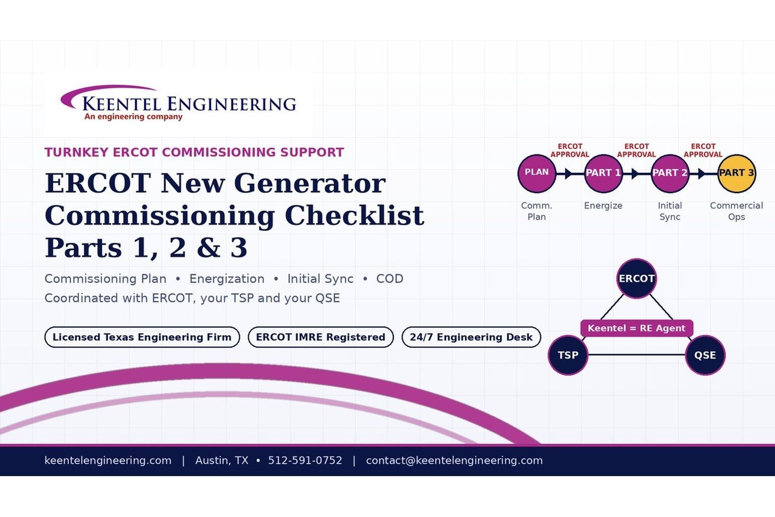
2026 ERCOT commissioning guide covering the Commissioning Plan, Checklist Parts 1–3, BESS requirements, TSP/QSE coordination, field testing and COD.

By SANDIP R PATEL
•
September 22, 2026
Learn PRC-030-1 R1 event detection requirements for inverter-based resources, SEL platforms, disturbance monitoring, and audit-ready compliance.
By SANDIP R PATEL
•
September 22, 2026
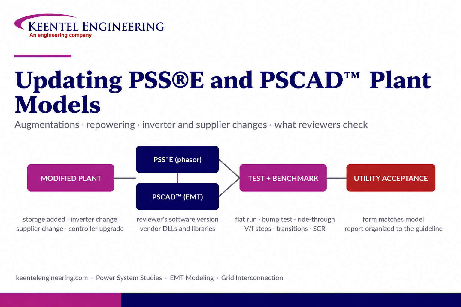
Learn how PSS®E and PSCAD™ model updates support plant augmentations, repowering, equipment changes, testing, benchmarking, and grid compliance.





