A Coordinated Electric System Interconnection Review—the utility’s deep-dive on technical and cost impacts of your project.

Challenge: Frequent false tripping using conventional electromechanical relays
Solution: SEL-487E integration with multi-terminal differential protection and dynamic inrush restraint
Result: 90% reduction in false trips, saving over $250,000 in downtime

The three operating regions you have to design to

Device Output vs voltage Response Best suited to Main limitations
Mechanically switched capacitor or reactor Proportional to voltage squared Seconds; discrete steps; limited switching operations per day Steady-state reactive supply, voltage profile, loss reduction No dynamic capability; step voltage change on switching; capability collapses when most needed
Static var compensator Capacitive branches proportional to voltage squared A few cycles; continuously controllable Continuous control where cost matters and deep voltage support is not the driver Square-law capability loss; harmonic filters are part of the plant and interact with the network
STATCOM Approximately proportional to voltage — constant current capability One to two cycles closed loop; converter response faster still Voltage stability margin, weak interconnections, fast disturbance recovery, flicker and unbalance compensation Higher capital cost; converter losses; adds a converter and its control dynamics to the network
Synchronous condenser Governed by machine capability and excitation Excitation response in the hundreds of milliseconds; inherent inertial response instantaneous System strength and inertia, short-circuit contribution, black start support Rotating plant with maintenance and losses; slower controlled response than a converter
STATCOM with energy storage Reactive as a STATCOM, plus real power within the storage rating As STATCOM for reactive; real power limited by storage Where a real power deficiency is part of the problem Cost and complexity of the storage; different failure and maintenance profile
Service area What we do for SST campuses Typical deliverables
Grid interconnection Site screening, large-load applications, independent studies, utility and RTO coordination in ERCOT, NYISO, PJM and other markets Screening reports, application data packages, load flow, contingency and stability studies, study review memos
EMT modeling Model requirements, vendor model review, campus aggregation, ride-through, weak-grid, control interaction and load-oscillation studies EMT model specifications, model acceptance reports, PSCAD study reports, SCR screening
MV/MVDC system studies AC and DC short-circuit, DC protection philosophy, AC protection, arc flash, grounding, insulation coordination Study reports, protection philosophy documents, settings files, arc flash labels, interface control documents
Power quality Emission requirements, frequency scans, IEEE 519-2022 compliance, filter sizing, flicker assessment Harmonic study reports, filter specifications, monitoring plans
Substation and transmission design HV/EHV substations, MV collectors, transmission lines, utility interface protection Physical and electrical drawing packages, specifications, bills of material, protection and control design
NERC compliance Registration and applicability, ride-through requirements, model validation, monitoring, compliance programs Applicability assessments, compliance programs, evidence packages, model validation reports
Owner's engineer and QA/QC SST, storage and substation specifications, design reviews, FAT and SAT plans and witnessing, multi-unit QA Specifications, review comments, test plans, witness reports, due diligence reports
Onsite generation and BESS Role definition and sizing, DC bus control architecture, fire and code compliance coordination, performance testing Sizing studies, control architecture documents, specifications, test procedures

Storage and generation

Term Meaning
AFE Active front end. The actively switched AC/DC stage of an SST that connects to the MV grid and sets its grid behavior.
Aggregated model A model in which many converters are represented by a smaller number of equivalent converters to make campus-scale simulation practical.
Arc flash The release of energy from an electric arc fault, assessed as incident energy at a working distance to set PPE and safe work practices.
BESS Battery energy storage system.
Blocking Turning off all converter switches so the converter stops feeding current, used to limit DC faults.
Composite load model A positive-sequence load model that combines several load types, such as motors, electronics and static loads.
DAB Dual active bridge. An isolated DC/DC converter topology with active bridges on both sides of a high-frequency transformer.
DC-link The internal DC capacitor bank between converter stages.
EMT Electromagnetic transient simulation. Time-domain simulation with microsecond time steps, used to study fast converter and network behavior.
FAT Factory acceptance test.
Grid-forming A converter control mode that sets its own voltage and frequency reference rather than following the grid's, providing support to weak grids.
HIL Hardware-in-the-loop testing, in which a real controller is tested against a real-time simulation.
IBR Inverter-based resource. Generation or storage connected to the grid through power electronics.
Insulation coordination Matching the insulation strength of equipment to the voltage stresses the system produces, with surge protection where needed.
ISC/IL The ratio of available short-circuit current to maximum demand load current at the point of common coupling, used to set IEEE 519 limits.
ISOP Input-series, output-parallel. A modular converter arrangement that shares a high input voltage across cells in series and combines their outputs in parallel.
Large load A load large enough to affect transmission system reliability. Definitions vary, for example 75 MW and above under Texas SB 6, or loads above 20 MW in the federal rulemaking proposal.
LVDC Low-voltage DC, such as 800 VDC or ±400 VDC rack distribution.
MFT Medium-frequency transformer. The compact isolation transformer inside an SST, operating at kilohertz frequencies.
MMC Modular multilevel converter. A converter built from many submodules with their own capacitors, producing a stepped multilevel waveform.
MVDC Medium-voltage DC distribution, roughly 1 kV to 35 kV DC in common usage.
OE Owner's engineer. An independent engineer representing the owner's technical interests.
PCC / POI Point of common coupling / point of interconnection, where the campus connects to the utility system and where compliance is usually assessed.
PLL Phase-locked loop. The control element that tracks grid voltage phase and frequency.
Positive-sequence model A fundamental-frequency, balanced dynamic model used in PSS®E, PSLF and similar tools.
Ride-through The ability to stay connected and keep operating during and after a grid disturbance within defined limits.
SAT Site acceptance test.
SCR Short-circuit ratio. Available short-circuit power divided by converter rating, a measure of grid strength.
SiC Silicon carbide, a wide-bandgap semiconductor material that allows higher voltage, higher frequency switching.
SST Solid-state transformer. A power electronic converter with a high-frequency isolation stage that replaces a 60 Hz transformer and rectifier chain.
Supraharmonics Emissions in the 2 kHz to 150 kHz range, above the range covered by most harmonic limits.
TDD Total demand distortion. Harmonic current distortion relative to maximum demand current, used in IEEE 519.
WSCR Weighted short-circuit ratio. An SCR screen that accounts for several inverter-based plants sharing a network area.

Links were current at publication (November 2026). Large-load rules, NERC actions and standards editions are changing quickly, so confirm current versions before relying on them.


Large-load reliability and NERC


Federal and state large-load rules


Solid-state transformers and DC data center power


Standards referenced (consult the publisher for the current edition)

Step 5 — options. Replacing or retrofitting the drives with active-front-end or 18-pulse units at about 5% THDi gives a TDD of about 1.5%. An active harmonic filter sized for the 5th and 7th could achieve a similar result at the facility level. A passive 5th-harmonic tuned filter would also work but must be checked for resonance with the utility system and with any future capacitors.


What this means for you.


The same drives can be compliant on a strong system and non-compliant on a weak one. Ask your utility for the maximum short-circuit current at the PCC early in design. If the ratio is below 50, plan for low-harmonic drives or filtering from the start; it is much cheaper than retrofitting.


9. Inverter-based resources: solar, storage and wind


Solar PV, battery energy storage and full-converter wind turbines use pulse-width-modulated inverters with output filters. They are generally low-distortion sources. IEEE Std 1547-2018 (distribution-connected resources) and IEEE Std 2800-2022 (transmission-connected resources) limit their current distortion — total rated-current distortion (TRD) of 5% with individual limits by order, measured against rated current rather than present output. In practice, quality inverters measure 1–3% at rated output.


Three cautions apply:


  1. Percentages rise at low output. At 10% of rated output a 2% distortion (of rated current) looks like 20% THD. Limits referenced to rated current, like TDD, avoid this trap.
  2. Inverters change the system's impedance. Plant collector cables, inverter output filters and capacitor banks add capacitance. They can create resonances near the 5th to 13th harmonics on the 34.5 kV collector or at a 138 kV, 230 kV or 345 kV point of interconnection, amplifying background distortion that the plant did not create.
  3. Background distortion matters. Inverters can absorb or amplify existing voltage distortion depending on their control design. Utilities increasingly require harmonic impedance studies for new plants, sometimes using electromagnetic transient (EMT) simulation.


Keentel's articles on harmonic resonance and on
weak-grid inverter stability cover these interactions in depth.


10. Data centers and other electronic facilities


Data centers are a special case because almost all their load is electronic. Points to check:


  • UPS rectifiers. Double-conversion UPS units with IGBT rectifiers typically draw less than 5% THDi at rated load, rising at low load. Older six-pulse or 12-pulse thyristor UPS rectifiers may need input filters.
  • Server and network power supplies. Modern units with active power factor correction have low 3rd harmonic. Legacy equipment does not. Measure a representative panel rather than assuming.
  • 208Y/120 V and 415Y/240 V distribution. Check neutral current and transformer K-factor as in Sections 4 and 7.
  • Generator operation. Test UPS and generator compatibility at the actual load level. Generator THDv can be three to four times the utility THDv for the same load.
  • Cooling plant. Chiller, pump, fan and cooling distribution unit drives often contribute more low-order harmonics than the IT load. Specify low-harmonic drives where the facility is large relative to the utility source.
  • Large-load interconnection. Utilities and grid operators now treat large data centers as high-impact loads. Harmonic studies and power quality monitoring are increasingly part of interconnection requirements, alongside ride-through and dynamic studies.


11. How a harmonic study is done


A harmonic study answers four questions: How much harmonic current will the facility inject? What voltage distortion will it cause? Will any resonance amplify it? What is the cheapest reliable fix? Keentel's typical workflow:


  1. Gather data. Single-line diagram; utility short-circuit data (maximum and minimum) at the PCC; utility background distortion if known; transformer impedances; cable lengths; capacitor banks and filters; drive, UPS and inverter data sheets with harmonic spectra.
  2. Measure existing conditions. For existing facilities, install class-compliant power quality meters at the PCC and key buses for at least one week, capturing 10-minute and 3-second data up to the 50th harmonic.
  3. Build the model. Represent sources as harmonic current injections and the network as frequency-dependent impedances, including transformer phase shifts that can cancel 5th and 7th harmonics between delta-delta and delta-wye units.
  4. Run a frequency scan. Plot driving-point impedance versus frequency at each important bus to find resonances, for all credible system configurations (tie breakers open/closed, capacitor steps in/out, generator versus utility).
  5. Run harmonic load flow. Calculate harmonic currents and voltages and compare them with IEEE 519 at the PCC and with equipment limits (IEEE 18 for capacitors, C57.110 for transformers) inside the facility.
  6. Design mitigation. Compare options for performance, cost, losses, footprint and future flexibility.
  7. Verify. Measure again after installation and document compliance with the statistical criteria.


12. Fixing harmonics: options compared
Radial vs. Loop (Ring) Distribution for US Residential and Commercial Developments: An Engineering Guide

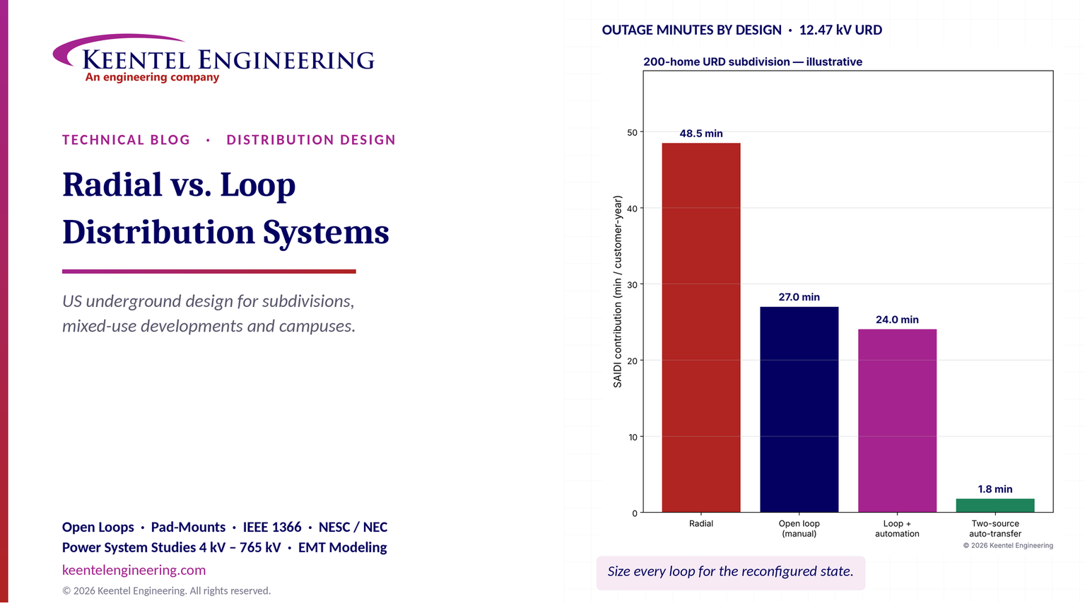
Radial vs. loop distribution systems comparison showing outage minutes and reliability.
Calendar icon. D

November 06, 2026 | Blog

Part A — Radial vs. Loop Distribution at a Glance


Every new subdivision, mixed-use development, business park and campus in the United States needs a medium-voltage (MV) distribution system: the cables, switches, fuses and pad-mounted transformers that carry power from the utility's distribution substation to the low-voltage services at each home or building. The first and most important layout decision is the topology — how those pieces are connected.


Two arrangements dominate. In a radial system, power flows along a single path from the source to each transformer. In a loop system — called a "ring main" in much of the world, and usually built in the US as an open loop — the cable leaves the source, passes through each transformer and returns to the source or to a second source, with one switch left open so that power still flows radially in normal operation. When a cable section fails, crews isolate it and close the open point, and every transformer is fed again from the other direction.


The choice affects first cost, outage duration, maintenance flexibility, voltage performance, arc-flash exposure and how easily the system can absorb electric vehicles, heat pumps and rooftop solar. This guide works through that choice in US terms: US voltages (12.47Y/7.2 kV, 13.2Y/7.62 kV, 13.8 kV, 24.9Y/14.4 kV and 34.5Y/19.92 kV primaries; 120/240 V, 208Y/120 V and 480Y/277 V secondaries), US equipment (loop-feed pad-mounted transformers, separable load-break connectors, pad-mounted switchgear and sectionalizing cabinets) and US codes and standards (NESC, NEC, IEEE C57 and C37 series, IEEE 1366 reliability indices and IEEE 1584 / NFPA 70E for arc-flash).


In plain terms: a radial system is a dead-end street — if a tree falls across it, everyone past the tree is stuck until it is cleared. An open loop is a street that connects back to the main road at both ends with a gate closed in the middle. If one block is blocked, you open the barricades around it, open the gate, and everyone gets home the other way. But if the main road itself is closed, the loop does not help unless its second end connects to a different main road.


Key comparison

Attribute Radial Open loop (US "ring main") Primary-selective Secondary network
Supply paths to each transformer One Two (one normally open) Two feeders, one selected at a time Several feeders in parallel
Typical US application Rural laterals, small developments, temporary service Standard for residential URD subdivisions and commercial parks Hospitals, data centers, critical commercial Dense downtown cores, large campuses
Effect of a primary cable fault All customers downstream of the operating fuse lose power until repair (hours) Customers on the faulted half lose power until switching (typically 30–120 min manual); repair is done with no outage Automatic or manual transfer to the alternate feeder (seconds to minutes) Usually no interruption
Protects against loss of the feeder or substation? No Only if the loop's two ends come from different feeders Yes, if the two feeders are independent Yes
Relative first cost (MV portion) 1.0 (baseline) About 1.1–1.4 About 1.4–2.0 About 2.5–4+
Switching skill required Low Moderate (load-break elbows or switchgear, written switching orders) Moderate to high High (network protectors, specialized crews)
Main design constraint Voltage drop and fuse coordination Each half must carry the whole loop after reconfiguration Each feeder must carry both loads Network protector and secondary design

Results from Keentel's illustrative 200-home subdivision model


Keentel modeled a 200-home all-electric subdivision on a 12.47Y/7.2 kV feeder from a 69/12.47 kV substation. The primary is 1/0 AWG aluminum, 15 kV class, full concentric neutral cable, direct buried, with 25 single-phase 75 kVA loop-feed pad-mounted transformers (eight homes each). Inputs and full derivations are in Part B.

Result Value
Diversified feeder-level demand (6.5 kVA per home) 1,300 kVA
Current if all 200 homes ride on one single-phase loop 181 A — at the limit of 200 A load-break connectors
Current per loop with three single-phase loops (one per phase) 60 A
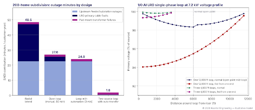
Worst primary voltage, one 12,000 ft loop, normal (open point mid-loop) 98.3% of source (1.7% drop)
Worst primary voltage, same loop fed from one end after a fault 94.0% of source (6.0% drop) — unacceptable with secondary drop added
Worst primary voltage, three 4,000 ft loops, fed from one end 99.3% of source
Outage minutes per customer-year (SAIDI contribution), radial 48.5
Same, open loop with manual switching (90 min) 27.0
Same, loop with automated sectionalizing (3 min) 24.0
Same, loop with two independent sources and auto-transfer 1.8
Available fault current at a 75 kVA, 2% impedance pad-mount secondary about 14.7 kA at the terminals; about 7.0 kA at a meter 100 ft away

Figure 1. Keentel's illustrative model of a 200-home URD subdivision. Left: outage minutes per customer-year by design, split into upstream feeder and substation outages, URD cable faults and pad-mount transformer failures. Right: primary voltage around a 1/0 Al single-phase loop at 7.2 kV for one long loop and for three shorter loops, in normal configuration and when fed from one end only.


Five lessons


  • The loop's real benefit is restoration time, not fewer faults. A loop does not prevent cable faults. It turns a six-hour repair outage into a one- to two-hour switching outage, and lets the repair be done with the customers back in service.
  • A loop fed from one feeder breaker does not protect against feeder or substation outages. In the model, upstream outages contribute 22.5 minutes per customer-year to every single-source design. Only a second, independent source with fast transfer removes that block.
  • Size the loop for the reconfigured state. In normal operation each half carries half the load; after a fault one half may carry all of it. Connector ratings, cable ampacity and voltage drop must all be checked for the worst open-point location.
  • Shorter loops and phase balancing beat bigger cable. Splitting one long single-phase loop into three loops on three phases cut the reconfigured voltage drop from 6.0% to 0.7% without changing the cable size.
  • Electrification changes the numbers. All-electric homes with heat pumps and EV charging can double the diversified demand that older design rules assumed. Loops designed today must be checked against tomorrow's load.


Engineering review of common statements about radial and ring systems

Statement often heard Keentel's check
"A radial system has one path only, lower cost, and a fault interrupts supply downstream." Correct in principle. In practice the fuse that operates is usually the lateral fuse at the riser or tap, so every customer on that lateral is interrupted — not only those "downstream" of the fault. Pure radial URD laterals are normally built with fused taps and radial-feed pad-mounted transformers, not with ring switching units at each transformer.
"A ring main system provides two supply paths and higher reliability." True for cable and section faults, provided the ring is built and operated as an open loop and each half can carry the full load. If both ends of the loop come from the same feeder breaker, the second path does not help when that breaker, feeder or substation is out.
"A faulty section can be isolated." Yes, but in a typical US residential loop isolation is manual: crews read fault indicators, operate load-break elbows or switches with hot sticks, and follow a written switching order. Expect 30 to 120 minutes, not seconds, unless the loop has automated switchgear and a fault location, isolation and service restoration (FLISR) scheme.
"The ring normally operates with a Normally Open Point." Correct and essential. A closed ring fed from one breaker would see fault current from both directions; isolating the faulted section would then require directional or differential protection at every switching point. Closed-loop schemes exist in the US, but on campuses and in dense commercial systems with relayed switchgear and communications, not in typical subdivisions.
"RMU = ring main unit, which switches and isolates cable sections." The term is common internationally. In US practice the same function is provided by loop-feed pad-mounted transformers with load-break elbows, pad-mounted switchgear (load-interrupter switches and fault interrupters, IEEE C37.74) and sectionalizing cabinets. The protection inside each transformer is typically a bayonet fuse in series with a current-limiting backup fuse.
"Supply can be restored from the alternative direction, subject to network capacity." The key engineering caveat. After reconfiguration one feed carries the whole loop, so cable ampacity, connector ratings (200 A load-break vs. 600 A dead-break), fuse sizes and voltage drop must all be checked for that state.
"Choose by reliability need, cost and utility requirements." Correct, and in most US territories the utility's service standards decide. Many utilities require loops for all new residential URD above a few lots; developers fund some or all of the line extension under tariff rules.
"Grid station" In US terms, the distribution substation, for example 69/12.47 kV or 115/13.2 kV, with feeder breakers and relays.

Part B — Radial vs. Loop Distribution: A US Engineering Guide

1. Where the distribution system begins and ends


A US distribution system starts at the low-voltage side of the distribution substation, where a transmission or sub-transmission supply (commonly 69, 115 or 138 kV) is stepped down to a primary distribution voltage. Each substation transformer feeds a bus, and each bus feeds several feeders through feeder breakers or reclosers with overcurrent relaying (devices 50/51 and 50N/51N, often with 79 reclosing).


A feeder typically leaves the substation as an underground "getaway," then runs as overhead three-phase mainline or as underground mainline in duct banks. New developments are connected by underground laterals, usually from a riser pole (a fused cutout and surge arresters at a dip pole) or from pad-mounted switchgear on an underground mainline.


From there, the developer's system — usually designed to the utility's service standards and often built by the developer's contractor, then turned over to the utility — distributes primary voltage through the development to pad-mounted transformers. Each transformer serves several homes, or one commercial building, at secondary voltage.

Level Typical US voltages Typical equipment
Sub-transmission supply 69, 115, 138 kV Substation high-side breaker or circuit switcher, power transformer with load tap changer
Primary distribution 12.47Y/7.2 kV, 13.2Y/7.62 kV, 13.8 kV, 24.9Y/14.4 kV, 34.5Y/19.92 kV Feeder breakers and reclosers, overhead mainline, underground cable, pad-mounted switchgear
Residential secondary 120/240 V single-phase Single-phase pad-mounted transformers (25–167 kVA), secondary pedestals
Commercial secondary 208Y/120 V, 480Y/277 V three-phase Three-phase pad-mounted transformers (75–3,750 kVA and larger)

Most new residential underground distribution (URD) in the US is single-phase: one phase conductor at the line-to-neutral voltage (for example 7.2 kV on a 12.47Y/7.2 kV system), with a concentric neutral that is grounded at every transformer. Commercial parks and campuses use three-phase loops. The topology choice applies to both.


2. The four main topologies


2.1 Radial


In a radial system each transformer has exactly one supply path. A radial URD lateral leaves a fused riser or a fused switchgear way and passes from transformer to transformer, ending at the last one. The transformers are radial-feed units with a single primary bushing, or loop-feed units with one bushing left unused.


Strengths. Lowest first cost, simplest protection (one fuse at the source of the lateral, plus each transformer's internal fuse), simplest operation, minimum cable length.


Weaknesses. Any primary cable fault blows the lateral fuse and interrupts every customer on the lateral until the cable is located, excavated and repaired or replaced. For direct-buried cable that commonly takes four to twelve hours, and longer if a whole section must be replaced. Maintenance and testing require an outage.


Where it fits. Small developments of a few lots, single commercial services, temporary construction power, rural laterals and the short "spurs" off a loop that serve one or two transformers.


2.2 Open loop (the US "ring main")


An open loop leaves a source point, passes through each loop-feed pad-mounted transformer and returns to the source point (a "single-source loop") or to a different source point (a "two-source" or "tie" loop). One point in the loop is left open — the normally open point (NOP) — so each half of the loop operates radially.


Each loop-feed transformer has two primary bushings (commonly marked H1A and H1B) connected by an internal loop bus, so current can pass through the transformer to the next one. The transformer fuse protects only the transformer, not the loop.


Normal operation. Each half of the loop is fed from its own fused source. A fault on one half blows that half's fuse; the other half stays in service.


Restoration. Crews read the faulted circuit indicators (FCIs) mounted on the elbows at each transformer to find the faulted cable section, then:


1. open (or park) the elbows on each side of the faulted section, isolating it;

2. close the normally open point;

3. replace the blown source fuse and re-energize.

Every transformer is then back in service, fed from one end or the other, and the faulted cable can be repaired at leisure.


Strengths. Short outages for cable faults, repair without customer outage, ability to de-energize any section for testing or maintenance, and a natural path for future load growth.


Weaknesses. More cable (the return leg), loop-feed transformers, more switching points, and the need to design every element for the reconfigured state. A single-source loop gives no protection against loss of the feeder or the substation.


2.3 Primary-selective


Each transformer — or each building's switchgear — has two primary supplies from two different feeders, labeled A and B. Only one supplies the load at a time. Selection is by manual switches, or by automatic transfer in pad-mounted switchgear with voltage sensing, typically completing in a few seconds.


Strengths. Protects against loss of a feeder and, if the feeders come from different substation buses or substations, against bus or transformer outages too.


Weaknesses. Double the primary cable to each transformer, transfer equipment, and coordination with the utility on how much load each feeder can pick up.


Where it fits. Hospitals, data centers, water and wastewater plants, emergency services and critical industrial loads. Keentel's related guide on MV architecture for data centers covers primary-selective and main-tie-main switchgear in detail; this guide focuses on development-scale networks.


2.4 Secondary-selective and secondary networks


Secondary-selective. Two transformers, each fed from a different primary, supply two secondary buses joined by a normally open tie breaker. Common in large commercial buildings and campuses at 480Y/277 V.


Spot networks. Two or more transformers, each fed from a different primary feeder, are paralleled on one secondary bus through network protectors — air circuit breakers with reverse-power relaying that open automatically when their feeder is faulted. A single building can lose a feeder with no interruption at all.


Grid (area) networks. Many transformers paralleled on a meshed 208Y/120 V secondary grid, fed by several primary feeders, serving dense downtown cores.


Networks deliver the highest reliability but at several times the cost of radial or loop systems. Rooftop solar and other distributed energy resources (DER) can also cause network protectors to cycle or block exports, so DER on networks needs special study.


2.5 Express feeders and closed loops


Express feeders carry a large block of load (for example a data hall or industrial plant) directly from the substation with no other customers attached, so feeder exposure and outage frequency are small.


Closed loops. A ring operated closed delivers fault current to every point from both directions. Fuses and simple overcurrent devices cannot isolate a single faulted section in that configuration. Closed loops require relayed switchgear at each node with directional overcurrent or line differential protection, and usually high-speed communications — practical for campuses and utility downtown systems with dedicated protection engineering, but rarely for residential subdivisions.


3. US equipment for loops: what replaces the "ring main unit"


3.1 Loop-feed pad-mounted transformers


Single-phase pad-mounted transformers are covered by IEEE C57.12.38; three-phase pad-mounted transformers by IEEE C57.12.34; enclosure integrity by IEEE C57.12.28 (and C57.12.29 for coastal environments). Efficiency is set by US Department of Energy rules (10 CFR Part 431).


A typical loop-feed residential unit has:


  • two primary bushing wells or integral bushings (H1A and H1B) for 200 A load-break elbows, plus parking stands;
  • an internal bayonet fuse (expulsion type, replaceable from outside with a hot stick) in series with an internal partial-range current-limiting fuse, coordinated so the bayonet clears low-current faults and overloads and the current-limiting fuse clears high-current internal faults;
  • sometimes an oil-immersed load-break switch (two-position, four-position or "T-blade") that can open either side of the loop or disconnect the transformer, which simplifies switching;
  • a secondary compartment with 120/240 V spades or bushings.


3.2 Separable connectors


Separable insulated connectors are covered by IEEE 386. Two families matter for loop design.

Connector class Typical continuous rating Operation Use
200 A load-break elbows 200 A Can be opened and closed under load with a hot stick; have a fault-close rating (commonly 10 kA symmetrical) Residential loops, transformer taps
600 A (and 900 A) dead-break connectors 600 A (900 A) De-energized operation only Feeder mainlines and switchgear terminations

Two practical consequences follow. First, a residential loop built entirely with 200 A elbows must never carry more than 200 A — including in the reconfigured state. Second, elbows are not fault-interrupting devices: they must never be used to interrupt a fault, and their fault-close rating limits where they may be closed into.


3.3 Pad-mounted switchgear and sectionalizing cabinets


Pad-mounted switchgear (IEEE C37.74) combines load-interrupter switches and fault-interrupting ways in a ground-level enclosure. Fault-interrupting ways use either power fuses or vacuum fault interrupters with electronic overcurrent controls (IEEE C37.60). Switchgear is used where a loop or lateral leaves an underground mainline, where several loops meet, and where automation is planned.


Sectionalizing cabinets (junction cabinets) are low-cost enclosures with 200 A or 600 A junctions that allow cables to be split, tapped or isolated by moving elbows, without switching capability beyond what the elbows provide.


3.4 Cable


US URD primary cable is generally made to ICEA S-94-649 (concentric neutral cables rated 5–46 kV) and AEIC CS8 specifications, with cross-linked polyethylene (XLPE or TR-XLPE) or ethylene-propylene rubber (EPR) insulation. Insulation level is usually specified at 100% or 133%.

Primary class Typical residential loop conductor Typical mainline or commercial conductor
15 kV (12.47/13.2/13.8 kV systems) 1/0 AWG Al, full concentric neutral 4/0 AWG Al to 1,000 kcmil Al, one-third neutral
25 kV (24.9 kV systems) 1/0 AWG Al 4/0 to 750 kcmil Al
35 kV (34.5 kV systems) 1/0 to 2/0 AWG Al 4/0 to 1,000 kcmil Al

Cable ampacity depends heavily on installation: direct burial or duct bank, depth, soil thermal resistivity, ambient earth temperature, mutual heating from adjacent circuits and load factor. Calculate it with IEEE 835 tables or the Neher–McGrath method rather than a single "rule of thumb" value. As an order of magnitude, 1/0 Al 15 kV URD cable carries roughly 150–200 A depending on installation, and 4/0 Al roughly 225–300 A.


3.5 Surge protection at the open point


A surge traveling along an underground cable reflects at an open end and can nearly double in voltage. The normally open point is therefore the most exposed location in the loop. Common US practice (IEEE C62.22 application guidance) is to fit elbow-type or parking-stand arresters at the open point in addition to riser-pole arresters. When the open point is moved during switching, the arresters must move with it.


4. Codes and standards that apply

Topic Utility side (NESC) Customer-owned side (NEC, NFPA) Equipment and practice standards
Installation, burial, clearances NESC (ANSI C2) Part 3, Rules 350–354 (burial depth, separation from other utilities, warning tape) NEC Article 300 and, in the 2023 edition, Article 305 (wiring over 1,000 V, including the cover-depth table formerly at 300.50) and Article 311 (medium-voltage conductors and cable) Utility service standards and specifications
Grounding NESC Rules 92–97 and 354; multigrounded neutral NEC Article 250 IEEE 80 (substations), IEEE 142
Transformers NESC Part 1 and Rule 381 NEC Article 450 IEEE C57.12.38, C57.12.34, C57.91 (loading)
Switchgear and connectors — NEC Article 490 IEEE C37.74, C37.60, IEEE 386, IEEE C37.41/C37.47 (fuses)
Services NESC Rule 230/Part 2 NEC Article 230 Utility service requirements
Worker safety, arc flash NESC Part 4, Rule 410 NFPA 70E IEEE 1584-2018
Reliability metrics — — IEEE 1366
Cable testing — — IEEE 400, 400.2 (VLF), 400.3 (partial discharge)
DER — NEC Articles 690, 705, 706, 625 (EV) IEEE 1547-2018, UL 1741 SB

Expected unserved energy sums the expected shortfall over every hour:

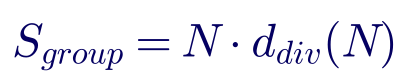
where N is the number of homes and d(N) is the diversified demand per home for a group of that size, taken from the utility's design tables or from metered data for similar homes in the same climate.


Historic US design rules for gas-heated homes used roughly 4–6 kVA per home at the transformer level. All-electric homes with heat pumps and backup resistance heat, and homes with Level 2 electric-vehicle chargers (7.2–11.5 kW each), can push the transformer-level value to 8–15 kVA per home. Two features make electrification different:


  • Coincidence rises. Heat-pump strip heat runs in every home during the same cold morning. EV charging often starts at the same minute when a time-of-use rate begins. Diversity that used to be safe disappears.
  • Peak shifts. Winter mornings and late evenings can replace summer afternoons as the design peak, which matters for transformer and cable ratings (cooler ambient helps) and for voltage.


Worked example 1 — sizing a 200-home all-electric subdivision. Design assumptions (illustrative): eight homes per transformer at 10 kVA per home at the transformer level, and 6.5 kVA per home at the feeder level for 200 homes.

A 75 kVA single-phase pad-mount would see 80 kVA, about 107% of nameplate, at the short winter or evening peak. IEEE C57.91 thermal models normally allow short peaks above nameplate when the daily cycle and ambient are favorable, and many utilities permit peak loading of roughly 120–140% for residential units. The design therefore uses 25 transformers of 75 kVA, with a planned upgrade path to 100 kVA where EV adoption is high.

At 9 kVA per home — a plausible full-electrification future — the feeder-level demand becomes 1,800 kVA. Both values are carried into the loop design below.

Design basis Transformer-level kVA per home Feeder-level kVA per home 200-home feeder demand
Legacy gas-heat design 5–6 3.5–5 700–1,000 kVA
All-electric with heat pump 7–10 5–7 1,000–1,400 kVA
All-electric with heat pump and Level 2 EV 10–15 6.5–9 1,300–1,800 kVA

These ranges are illustrative. Use the utility's design tables and local metered data; they vary widely with climate, home size and rate design.


5.2 Commercial and mixed-use loads


Commercial loads are estimated from building-type load densities (for example, watts per square foot for office, retail and restaurant space), NEC Article 220 calculations for the service, and the owner's equipment schedules. The utility sizes its transformer on expected demand, usually well below the NEC calculated load. Mixed-use developments combine residential single-phase loops with three-phase loops or radial taps serving commercial pads.


6. Loop current and the reconfigured state


6.1 Single-phase vs. three-phase current


For a single-phase URD loop the current is the apparent power divided by the line-to-neutral voltage; for a three-phase loop it is divided by √3 times the line-to-line voltage:

Worked example 2 — loop current for the 200-home subdivision. On a 12.47Y/7.2 kV system with 1,300 kVA of feeder-level demand:

Arrangement Normal current per loop half Reconfigured current (one end feeds the whole loop) Check against 200 A elbows
One single-phase loop, 1,300 kVA 90 A 181 A 91% of rating — no margin for growth
One single-phase loop, 1,800 kVA (future) 125 A 250 A Exceeds 200 A rating
Three single-phase loops (one per phase), 433 kVA each 30 A 60 A 30% of rating
Three single-phase loops at 600 kVA each (future) 42 A 83 A 42% of rating

The single-loop design technically passes today but fails the future-load case and leaves no margin. Splitting the development into three loops, one on each phase, does three things at once: it balances the feeder phases, it cuts current per loop by a factor of three, and it reduces the number of customers affected by any one fault.


6.2 The N-1 rule for loops


The governing check for any open loop is the reconfigured case: the open point moved to one end of the loop so that one source carries every transformer. Each of the following must be rated for that case:


  • the source fuse or fault-interrupter at each end of the loop;
  • every cable section, including the sections nearest each source;
  • every load-break elbow and bushing (200 A) or dead-break connector (600 A);
  • every switch in pad-mounted switchgear or transformer load-break switches;
  • the voltage at the most remote transformer.


A loop that only works with the open point in the middle is a radial system with extra cable.


7. Voltage drop and losses


7.1 The distributed-load approximation


For a cable section of length L carrying a current I that is spread evenly along its length (many transformers of similar size), the voltage drop to the far end is about half the drop for a lumped load at the end:

where R and X are the loop impedance per unit length (for a single-phase circuit, phase conductor plus the return path), φ is the load power-factor angle and I is the current at the source end.

For 1/0 AWG Al with a full concentric copper neutral, Keentel used R ≈ 0.40 Ω and X ≈ 0.05 Ω per 1,000 ft of circuit (phase plus neutral, at operating temperature, neglecting the parallel earth return), with a 0.95 power factor. Real values depend on the cable construction and the share of neutral current returning through earth and parallel neutrals; use the manufacturer's data and the utility's modeling practice.


Worked example 3 — voltage drop around the loop. The single-loop design is 12,000 ft around, with 25 transformers evenly spaced and the open point in the middle. The three-loop design uses three 4,000 ft loops.

Arrangement Normal worst drop Reconfigured worst drop
One 12,000 ft loop, 1,300 kVA 1.5–1.7% 6.0%
Three 4,000 ft loops, 433 kVA each 0.2% 0.7%

A discrete calculation with 25 individual transformer loads (Figure 1, right) gives 1.7% and 6.0%, confirming the approximation.


Why 6% matters: the customer's service voltage must stay within ANSI C84.1 Range A (114–126 V on a 120 V base) under normal conditions, and Range B (110–127 V) is only tolerated for limited periods. The primary drop adds to the voltage drop in the feeder upstream of the development, the transformer's own regulation (1–2% at full load) and the secondary and service drop (often 2–4% to the farthest home). A 6% primary drop on the loop alone, on top of those, pushes the end-of-loop homes below Range A during the reconfigured condition — exactly when customers have already had an outage.


7.2 Losses


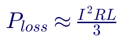
For a uniformly distributed load, the I²R loss in a section is one-third of the loss with the whole current flowing the full length:

For the single-loop design in normal configuration, each half carries 90.3 A over 6,000 ft:

For the three-loop design, each of six half-loops carries 30.1 A over 2,000 ft, for a total of about 1.45 kW at peak. With a loss factor of 0.3, annual losses are about 34,000 kWh for one long loop and 3,800 kWh for three loops. The three-loop layout may need some extra cable to reach the loop starting points, so compare the complete routes; the point is that current, not cable length, dominates losses.


7.3 Choosing conductor size


Upsizing from 1/0 to 4/0 Al roughly halves the resistance and raises ampacity, but costs more, uses larger elbows and terminations, and is heavier to install. In most residential developments, topology changes — more loops, shorter loops, phase balancing, a three-phase backbone to the loop starting points — achieve more than conductor upsizing. Reserve 4/0 and larger for backbones, commercial loops and loops with high future growth.


8. Protection and fuse coordination


8.1 The protection chain


A typical residential URD loop has four levels of overcurrent protection:


1. Substation feeder breaker or recloser with phase and ground overcurrent relays (51/51N, often with 50/50N instantaneous elements).

2. Lateral protection at the riser pole (expulsion fuse in a cutout, sometimes a current-limiting fuse) or a fault-interrupting way in pad-mounted switchgear.

3. Transformer protection: bayonet fuse in series with a partial-range current-limiting fuse inside each pad-mount.

4. Secondary protection: the customer's service main breaker (NEC) and the transformer's thermal capability.

Each level must coordinate with the next, so that only the device nearest the fault operates.


8.2 Reclosing on underground circuits


Faults in underground cable are almost always permanent; reclosing onto them adds thermal and mechanical stress and can enlarge the damage. Many US utilities block reclosing on all-

underground feeders. On mixed overhead and underground feeders, utilities choose between:


  • fuse saving — a fast trip before the lateral fuse can blow, to clear temporary overhead faults, at the cost of momentary interruptions for everyone on the feeder;
  • fuse blowing — letting the lateral fuse clear first, which reduces momentaries but turns temporary overhead faults on fused laterals into sustained outages.


Laterals feeding URD loops are usually treated as fuse-blowing, because the riser fuse is the right device to clear a permanent cable fault.


8.3 Transformer fusing


Worked example 5 (part 1) — transformer primary current. A 75 kVA single-phase transformer on 7.2 kV:

The bayonet fuse is selected from the transformer manufacturer's fusing table, which balances three needs: carrying permitted overloads and inrush without melting, clearing secondary faults before the transformer is damaged, and coordinating with the lateral fuse upstream. Bayonet expulsion fuses have limited interrupting capability (on the order of a few kiloamperes), so a partial-range current-limiting backup fuse is placed in series to interrupt high-current internal faults. The backup fuse must never be the only device asked to clear low-current faults, which it cannot interrupt.


8.4 Lateral fuse sizing and the reconfigured state


The source fuse at each end of a loop must carry the full loop load after reconfiguration and still coordinate with the largest transformer fuse downstream and with the substation relay upstream. For the single-loop design, 181 A of reconfigured load pushes the riser fuse close to the limit of common distribution cutouts and makes coordination with the feeder relay difficult. For the three-loop design, 60 A of reconfigured load allows a moderate expulsion link that coordinates comfortably. This is another reason to keep loop loads modest.


8.5 Faulted circuit indicators and sectionalizing


Faulted circuit indicators (FCIs) mounted on the cable at each transformer elbow show which sections carried fault current. On a single-source loop, the FCIs between the source and the fault trip and those beyond do not; the fault lies between the last tripped and the first untripped indicator. FCIs with remote communication can feed outage management systems and shorten fault location from an hour to minutes.


8.6 Fault current at the secondary


Worked example 5 (part 2) — available fault current. A 75 kVA, 120/240 V transformer with 2.0% impedance:

Including a stiff primary source (8 kA available at the riser) lowers this only slightly, to about 14.7 kA at the transformer terminals. A 100 ft run of 4/0 Al service conductors reduces it to about 7.0 kA at the meter. Utilities publish available fault current so customers can confirm their service equipment interrupting ratings under NEC 110.9 and 110.10. Larger transformers (100–167 kVA) and lower impedances can exceed the 10 kA rating of common residential main breakers close to the transformer, so check service equipment ratings when transformers are upsized for electrification.


9. Reliability: what the loop buys


9.1 IEEE 1366 indices


US utilities report reliability with IEEE 1366 indices, based on sustained interruptions (longer than five minutes):

where Ni is the number of customers interrupted in event i, ri its restoration time, and NT the total customers served. Interruptions of five minutes or less are momentary and counted in MAIFI(E), not SAIDI. Major event days, identified with the IEEE 1366 "2.5 beta" method, are reported separately.


9.2 A simple component model


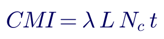
For a section of cable of length L (miles) with failure rate λ (failures per mile-year), serving Nc customers with restoration time t, the annual customer-minutes interrupted (CMI) are:

Worked example 4 — 200-home subdivision. Illustrative inputs:


  • 12,000 ft (2.27 mi) of primary cable, failure rate 0.03 failures per mile-year (typical published URD rates range from roughly 0.01 to over 0.1, depending on cable age, insulation type and installation quality) — 0.068 cable faults per year;
  • radial: every cable fault interrupts all 200 customers for a 6-hour repair;
  • open loop with manual switching: a cable fault interrupts the 100 customers on the faulted half for 90 minutes of location and switching;
  • loop with automated sectionalizing: the same 100 customers for 3 minutes;
  • 25 transformers failing at 0.003 per unit-year, each outage affecting 8 customers for 8 hours (the same in all designs);
  • upstream feeder and substation outages at 0.25 per year lasting 90 minutes, affecting all 200 customers in every single-source design, and lasting about 1 minute where a second independent source with automatic transfer exists.
Design Cable faults (min/cust-yr) Transformer failures Upstream outages Total SAIDI contribution
Radial (one lateral) 24.5 1.4 22.5 48.5
Open loop, manual (90 min) 3.1 1.4 22.5 27.0
Loop with automation (3 min) 0.1 1.4 22.5 24.0
Two-source loop with automatic transfer 0.1 1.4 0.3 1.8

Three lessons stand out:


  • The loop roughly halves the subdivision's outage minutes by turning repair time into switching time.
  • Automation on a single-source loop adds little once manual switching is reasonably fast, because upstream outages now dominate. (Restoration within five minutes would also count as momentary under IEEE 1366, so those minutes would leave SAIDI entirely.)
  • The second source is where the big gain lies. It only works if the second feeder is truly independent — a different substation bus or substation, a different route — and has capacity to pick up the load.


A fair comparison must also consider that a radial design would rarely put all 200 homes on one lateral. Split into four radial laterals, the cable-fault contribution falls to about 6.1 minutes — still twice the loop's 3.1 minutes, and with a six-hour outage for every affected customer rather than 90 minutes.


9.3 Frequency vs. duration


A single-source loop does not reduce how often customers are interrupted by cable faults (SAIFI) by much: the faulted half still loses power until switching. In the model, SAIFI falls only from 0.32 to 0.29. The loop's value is in duration. Customers notice both, but long outages drive complaints, spoiled food and frozen pipes.


10. Automation and FLISR


Fault location, isolation and service restoration (FLISR) uses automated switches or fault interrupters, sensors and communications — managed locally or by an advanced distribution management system (ADMS) — to isolate a faulted section and restore the healthy sections automatically, typically within one to five minutes.


For underground systems, automation lives in pad-mounted switchgear at the main branch points: motor-operated load-interrupter switches and vacuum fault interrupters with electronic controls (IEEE C37.60), voltage and current sensors, and radio or fiber communications. Individual residential loop-feed transformers are rarely automated; instead, automated switchgear divides a large development into zones, and each zone is a small manual loop.


Design considerations for automated loops:


  • Capacity checks before transfer. The scheme must confirm the alternate source can carry the transferred load, using real-time or seasonal limits.
  • Protection settings after transfer. Fault-interrupter settings that coordinated in the normal configuration may not coordinate after transfer. Use adaptive setting groups.
  • Cybersecurity and communications reliability. Utility distribution automation is outside NERC CIP but subject to utility security programs; campus owners need their own controls.
  • Arc-flash. Remote operation removes workers from the switching location, a safety gain in itself.


11. Grounding and the neutral


US distribution is predominantly four-wire multigrounded wye: the neutral is carried with the phase conductors and grounded at the substation, at every transformer and at intervals along the line (NESC Rule 96 sets minimum grounding for multigrounded systems). In URD, the cable's concentric neutral serves as the neutral conductor and part of the grounding system, and a ground rod or ring is installed at each pad-mount.


Practical points:


  • Neutral sizing. Single-phase URD loops normally use a full neutral (equal ampacity to the phase), because the neutral carries the full load current back. Three-phase cables may use a one-third neutral where the load is balanced.
  • Neutral corrosion. Older bare concentric neutrals in corrosive soils lost strands over time and raised fault and touch voltages. Jacketed cable is now standard.
  • Fault return. A ground fault on a URD loop returns mainly through the concentric neutral, which keeps fault current high enough to blow the fuse quickly. Broken neutrals are a recognized cause of slow-clearing faults and elevated touch voltages; cable testing should include neutral checks.
  • Customer side. The service neutral bonds to the customer's grounding electrode system under NEC Article 250; stray-voltage concerns on farms and pools trace back to neutral-to-earth voltage on multigrounded systems.


12. Arc-flash and switching safety


Operating load-break elbows, replacing bayonet fuses and working in secondary compartments are among the most hazardous routine tasks in URD work.


  • Primary compartment. Utility workers follow NESC Part 4, Rule 410, which requires arc-flash assessment and provides tables for typical distribution tasks; non-utility workers on customer-owned systems follow NFPA 70E. IEEE 1584-2018 calculates incident energy for three-phase equipment from 208 V to 15 kV; it does not model single-phase arcs, so single-phase 7.2 kV and 120/240 V tasks need the NESC or NFPA 70E table methods or engineering judgment.
  • Secondary compartment. A fault on the 240 V side of a 75 kVA unit draws about 14.7 kA, but on the primary this is only about 14,700 × 240 / 7,200 ≈ 490 A — a current the bayonet fuse may take seconds to clear. Long clearing times mean high incident energy at low voltage. Many utilities require de-energizing the transformer, or the highest PPE category, for secondary compartment work.
  • Switching orders. Every loop reconfiguration should follow a written, verified switching order with lockout/tagout, voltage testing and grounding of the isolated section before cable work begins.
  • Elbow operation. Load-break elbows interrupt load, not fault current. Closing an elbow into a faulted section is limited by its fault-close rating; isolate and test the section before re-energizing.


13. Electrification and DER


13.1 EVs and heat pumps


Electrification raises both peak demand and coincidence. Practical responses in loop design:


  • design transformer pads, secondary pedestals and conduit for the next transformer size;
  • limit homes per transformer (six to eight rather than ten to twelve) for new all-electric developments;
  • size the loop for the future reconfigured load (Worked example 2's 1,800 kVA case);
  • work with the utility on managed charging programs, which can shift EV load and protect transformers far more cheaply than larger equipment.


13.2 Rooftop solar and batteries


Residential solar under IEEE 1547-2018 and UL 1741 SB can raise secondary voltage at midday and reverse power flow through the pad-mount transformer.


  • Voltage. On long secondaries with many systems, voltage can exceed the 126 V upper limit of ANSI C84.1 Range A. Smart-inverter volt-var and volt-watt functions help; short secondaries and adequately sized transformers help more.
  • Loop reconfiguration. With the open point moved, the same DER is connected farther from the source, so voltage rise and hosting capacity change. Hosting capacity studies should cover the reconfigured state.
  • Protection. Small inverter-based DER contributes little fault current, so fuse coordination is rarely affected. However, inverters must cease to energize on loss of the utility source, which matters for crew safety when a loop section is isolated.
  • Batteries and backup. Home batteries with backup capability isolate from the grid during outages through transfer equipment; they reduce the customer impact of outages but do not change utility reliability indices.


14. Resilience: flood, wind and wildfire


Underground distribution removes most exposure to wind, ice and vegetation. In a hurricane or ice storm, URD subdivisions often keep power while overhead areas do not — until the overhead feeder that supplies them fails. Undergrounding the development does not undergird the feeder, which is another argument for two-source loops.


Underground systems have their own hazards:


  • Flooding. Pad-mounted transformers and switchgear in floodplains should be placed above the design flood elevation or specified as submersible. Saltwater from storm surge damages equipment that survives fresh-water flooding.
  • Dig-ins. Third-party excavation damage is a leading cause of URD faults. Warning tape, accurate as-builts and "call before you dig" (811) participation reduce it.
  • Wildfire. Underground cable eliminates ignition risk along those segments; pad-mounted equipment still needs defensible space and fire-resistant enclosures in high-risk areas.
  • Aging cable. First-generation polyethylene URD cable installed in the 1970s and 1980s has high failure rates from water treeing. Diagnostic testing — very-low-frequency (VLF) tan delta under IEEE 400.2 and partial discharge under IEEE 400.3 — prioritizes replacement or rejuvenation.


15. Costs (indicative)


Installed costs vary widely by region, soil, labor, trenching method and the post-2021 rise in transformer and switchgear prices. The ranges below are indicative for 2026 planning only.

Item Indicative installed cost
15 kV 1/0 Al URD cable, direct buried (trench, cable, backfill) $40–100 per foot
Same, in conduit $60–150 per foot
Single-phase pad-mounted transformer, 50–100 kVA $8,000–20,000 each
Three-phase pad-mounted transformer, 500–1,500 kVA $40,000–150,000 each
Sectionalizing cabinet $15,000–40,000
Manual pad-mounted switchgear $40,000–100,000
Automated pad-mounted switchgear with communications $80,000–200,000

For a residential loop, the incremental cost over radial is mainly the return leg of cable, the loop-feed transformer premium and open-point arresters — often 10–40% of the MV system cost.

Worked example 6 — is the loop worth it? Assume the loop adds $170,000 (about 2,500 ft of return cable and connection equipment). With a 7% discount rate and 30-year life, the capital recovery factor is:

The annualized cost is about $13,700 per year.


  • Residential subdivision. The loop saves about 4,300 customer-minutes per year in the model. At an illustrative residential value of $0.10 per customer-minute, that is about $430 per year — far below the cost. Utilities still build loops because they repair cable without outages, need fewer emergency crews, meet regulatory reliability targets and avoid long outages that drive complaints. The loop is a utility standard, not an outage-value calculation.
  • Commercial park. With 40 small commercial customers on the same cable and an illustrative $15 per customer-minute, the loop saves about 860 customer-minutes and $12,900 per year — close to break-even on outage value alone. For customers with higher outage costs (medical offices, data, food storage), the loop and often a second source pay for themselves.


Use real cost data and published value-of-service estimates for the customer mix; the method matters more than the illustrative numbers.


16. Developer and utility coordination


In most US territories the utility owns the distribution system in a development but the developer pays for some or all of it and often builds the civil work. Early coordination avoids redesign:


  • Line extension tariffs. Each utility's tariff defines allowances, contributions in aid of construction (CIAC), refund provisions and who installs what. Loop requirements, transformer sizes and switchgear locations come from the utility's design, not the developer's preference.
  • Easements and layout. Front-lot or rear-lot utility easements (commonly 10 ft wide), pad locations with required clearances in front of doors and around enclosures, and access for trucks.
  • Joint trench. Electric, telecom and sometimes gas in a common trench, with NESC separation rules (Rules 353 and 354) and the parties' agreements.
  • Conduit vs. direct burial. Conduit under roads and driveways is universal; full-conduit systems simplify future replacement but reduce ampacity and cost more.
  • Phasing. Build the backbone and loop sources in the first phase, so later phases close loops instead of hanging long radial stubs.
  • Customer-owned systems. Campuses and some commercial parks take service at primary voltage and own the MV loop. They are then responsible for design to the NEC, protection coordination with the utility, maintenance, testing and arc-flash studies.


17. Design checklist


1. Confirm the utility's service standards, primary voltage, available fault current and source options (one feeder or two).

2. Estimate diversified load for today and for full electrification.

3. Choose the topology: radial spurs only for one or two transformers; open loops for groups; two sources where outage cost or customer criticality justifies it.

4. Divide large developments into several loops, balanced across phases, with a three-phase backbone to the loop starting points.

5. Check every element for the reconfigured state: current, connector ratings, fuses, voltage drop.

6. Coordinate the protection chain: substation relay, lateral fuse, transformer bayonet and current-limiting fuses, customer main.

7. Place the normally open point for balanced loading, and install open-point arresters.

8. Provide FCIs at every transformer, and remote FCIs or automation where outage cost justifies it.

9. Check available fault current at secondaries and service equipment ratings.

10. Address flood elevation, dig-in protection, access and arc-flash practices, and document as-builts, switching diagrams and the normal open point location.


Part C — Three Anonymous Case Studies

These composite case studies are based on the kinds of problems Keentel Engineering sees on US projects. Names, locations and details have been changed or combined.


Case study 1 — An all-electric subdivision that outgrew its loop


Situation. A 420-home all-electric subdivision in the Southeast was built in three phases on a 12.47Y/7.2 kV feeder. The original design used two long single-phase 1/0 Al loops on the same phase, each serving about 210 homes through 50 kVA loop-feed transformers at ten homes per transformer. Within four years, heat-pump and EV adoption had changed the load. Transformers failed during a January cold snap. During a cable repair, with the open point moved to the end of one loop, customers at the far end reported lights dimming and heat pumps tripping on low voltage.


Analysis. Keentel rebuilt the loads from interval meter data: the coldest-morning diversified demand was 9.5 kVA per home at the feeder level and 13 kVA per home at the transformer level. Results:


  • Loop current. One loop carried 140 A in normal configuration and 277 A when reconfigured, beyond the 200 A elbow rating.
  • Voltage drop. The reconfigured primary drop reached 8%.
  • Transformer loading. The 50 kVA transformers ran at 260% of nameplate during the cold-morning peak.
  • Phase balance. Both loops sat on the same phase, so the feeder was badly unbalanced.


Engineered solution.


  • Re-divided the development into six loops, two per phase, fed from a new three-phase 4/0 Al backbone with a manual pad-mounted switchgear unit at the entrance.
  • Replaced overloaded transformers with 100 kVA units, and limited new groups to six or seven homes per transformer.
  • Added open-point arresters and remote FCIs.
  • Worked with the utility on a managed-charging enrollment campaign to stagger EV charging after the time-of-use start.


Outcome.


  • Loop loading. Reconfigured loop currents fell below 100 A.
  • Voltage. The worst-case primary drop fell below 1.5%.
  • Transformers. Transformer failures stopped.
  • Feeder. Phase unbalance at the feeder fell from 38% to under 10%.
  • Spare capacity. The new design leaves room for full electrification of the remaining lots.


Case study 2 — A university campus moves from radial to automated two-source loops


Situation. A university in the Mid-Atlantic owns a 13.2 kV campus distribution system fed from a utility-owned 69/13.2 kV substation with two transformers. Thirty-five buildings were served by radial feeders from the campus main switchgear. Several aging cable sections had failed in the past five years, each leaving labs, residence halls or the data center without power for six to twelve hours while the cable was located and spliced.


Analysis. Keentel's study combined three pieces of work:


  • Cable testing. VLF tan delta and partial discharge testing under IEEE 400.2 and 400.3 showed that 30% of the cable sections were in poor condition.
  • Reliability model. The model showed radial cable failures driving more than 80% of building outage hours.
  • Source split. The two substation transformers fed separate bus sections, so loops closed between the two bus sections would be protected against loss of either transformer or feeder.


Engineered solution.


  • Reorganized the campus into four open loops, each starting on bus section A and ending on bus section B, with the normally open points chosen to balance load.
  • Replaced the worst cable sections with 500 kcmil Al in duct bank.
  • Installed automated pad-mounted switchgear with vacuum fault interrupters at 12 nodes, with a local controller performing automatic isolation and restoration and checking capacity before each transfer.
  • Revised protection settings with adaptive groups for each configuration and coordinated the main breakers with the utility's relays.
  • Completed an IEEE 1584-2018 arc-flash study, which also gained from remote operation of the new switchgear.


Outcome.


  • Section faults. In the first three years two cable faults occurred; automatic restoration took under two minutes in each case, and only the building on the faulted section stayed out.
  • Outage hours. Campus outage hours fell by about 90%.
  • Maintenance. Maintenance outages for testing and splicing are now scheduled with no building outage.


Case study 3 — A mixed-use development with residential loops and a primary-selective medical building


Situation. A mixed-use development in Texas combined 300 homes, a retail center and a 60,000 ft² medical office building with imaging and outpatient surgery. The utility's standard design served everything from one 12.47 kV feeder with residential loops and a radial three-phase tap to the medical building. The medical tenant required a second source and had planned a large standby generator plant to compensate.


Analysis. Keentel reviewed the utility's feeder maps and outage history:


  • Source exposure. The development's feeder had averaged 1.8 sustained interruptions per year over five years, most of them upstream on the overhead portion.
  • Second source. A second feeder from a different substation transformer ran along the development's frontage road.
  • Medical building. It needed fast transfer, and imaging equipment could not tolerate repeated interruptions.


Engineered solution.


  • Residential loops: three loops per phase-balanced group, designed for the full-electrification reconfigured case, with loops from the development's first feeder.
  • Retail center: a three-phase open loop with one end on each feeder, through a sectionalizing cabinet, normally open at the retail transformer.
  • Medical building: primary-selective service through pad-mounted automatic transfer switchgear with two fault-interrupting incoming ways from the two feeders. The tariff's line-extension provisions governed how the second feed was funded; the tenant paid the incremental cost.
  • Coordinated the transfer scheme with the utility's reclosing so that the switchgear waits through reclose attempts before transferring, avoiding unnecessary transfers on temporary faults.
  • Right-sized the standby generator plant for life-safety and critical loads under NEC Articles 517 and 700, rather than the whole building.


Outcome.


  • Utility interruptions at the medical building. In the first two years the feeder had three sustained interruptions; each was a transfer of about 10 seconds, covered by UPS on critical equipment.
  • Generator savings. The smaller generator plant saved more than the cost of the second source.
  • Residential loops. The loops have handled two cable faults with switching restorations under 90 minutes.

Part D — 20-Question Technical FAQ

  • 1. What is the US equivalent of a "ring main" system?

    The open loop: an underground primary cable that passes through each loop-feed pad-mounted transformer or switch and returns to the source or to a second source, operated with one normally open point. Functionally it matches the international ring main; the equipment differs. US loops use loop-feed transformers with load-break elbows, pad-mounted switchgear and sectionalizing cabinets rather than compact ring main units.


  • 2. Why are US loops operated open rather than closed?

    With the loop open, each half is radial, so a simple fuse or overcurrent device at each source end can clear a fault and the rest of the loop stays in service. A closed loop feeds a fault from both sides; isolating one section then needs directional or differential relaying at every node, plus communications. That is practical for campuses and dense utility systems with relayed switchgear, but not economic for typical subdivisions.


  • 3. Does a loop reduce the number of outages?

    Not much for faults on the loop itself. A cable fault still blows the source fuse for that half, so those customers are interrupted. The loop sharply reduces duration: restoration takes the time to locate and switch (often 30–120 minutes) instead of the time to repair (often 4–12 hours). If the loop's two ends come from different feeders, it can also reduce outages caused by the feeder or substation.


  • 4. Does a loop protect against a substation or feeder outage?

    Only if its two ends connect to independent sources — different feeders, ideally from different substation buses or substations — and the alternate source has capacity to pick up the load. A loop whose ends both connect to the same riser or the same feeder breaker gives no protection against loss of that feeder.


  • 5. How long does it take to restore a manual URD loop?

    Typically 30 minutes to 2 hours: travel, reading the faulted circuit indicators, isolating the faulted section by opening load-break elbows or switches, closing the open point and replacing the blown fuse. Remote-reporting fault indicators and good switching diagrams shorten this. Automated pad-mounted switchgear with FLISR can restore in one to five minutes.


  • 6. How should I size cable and connectors in a loop?

    For the reconfigured state, with the open point moved to one end so one source carries the whole loop. Check the cable ampacity (IEEE 835 or Neher–McGrath, for the actual installation), the 200 A load-break or 600 A dead-break connector rating, the source fuse rating and the end-of-loop voltage. Then add margin for future electrification load.


  • 7. When should I use 200 A vs. 600 A connectors?

    Use 200 A load-break elbows on residential loops and transformer connections where the reconfigured current stays comfortably below 200 A and crews need to operate them under load. Use 600 A dead-break connectors on mainlines and backbones carrying more current, with switching done by switchgear rather than by the connectors. Never exceed the continuous rating in any configuration.


  • 8. Where should the normally open point be located?

    Typically near the electrical midpoint of the loop load, so each half carries similar current and has similar voltage drop. Also consider accessibility for crews, flood exposure and future load growth. Wherever it is, install surge arresters at the open point, because a surge reflecting at an open cable end can nearly double in voltage. Move the arresters if the open point is moved.


  • 9. Why does a pad-mounted transformer have two fuses?

    The bayonet expulsion fuse clears overloads and low- to moderate-current faults, and can be replaced from outside. Its interrupting capability is limited, so a partial-range current-limiting fuse in series clears high-current internal faults that would exceed the bayonet's rating. The two are coordinated by the manufacturer so each operates in its own current range.


  • 10. Should reclosing be enabled on feeders serving URD loops?

    On all-underground feeders, many utilities block reclosing because cable faults are permanent and reclosing adds stress. On mixed overhead and underground feeders, reclosing remains valuable for temporary overhead faults. The URD laterals are typically protected by fuses that are allowed to blow (fuse-blowing), so the underground cable is not repeatedly re-energized.


  • 11. How much load should I plan per home today?

    It depends on climate, home size, heating fuel and EV adoption. Older gas-heat designs used roughly 4–6 kVA per home at the transformer level. All-electric homes with heat pumps and Level 2 EV chargers can reach 10–15 kVA per home at the transformer level and 6.5–9 kVA at the feeder level. Use the utility's current design tables and local metered data, and design pads and conduit for the next transformer size.


  • 12. How many homes should share one pad-mounted transformer?

    Historically 8–12 homes on a 50 or 75 kVA unit. For new all-electric developments, 6–8 homes on 75–100 kVA units is increasingly common. Fewer homes per transformer shortens secondaries (better voltage, less loss) and reduces the impact of a transformer failure, at the cost of more transformers.


  • 13. What fault current should customers expect at the service?

    At the terminals of a 75 kVA, 2% impedance, 120/240 V transformer, about 15 kA; at a meter 100 ft away, about 7 kA. Larger and lower-impedance transformers raise these values. Utilities publish available fault current so service equipment can be rated under NEC 110.9 and 110.10. When transformers are upsized for electrification, recheck customers close to the transformer.


  • 14. How is arc-flash handled at pad-mounted equipment?

    Utility workers follow NESC Rule 410 arc-flash assessment and task tables; others follow NFPA 70E. IEEE 1584-2018 calculates incident energy for three-phase equipment, but not for single-phase 7.2 kV or 120/240 V arcs, so table methods or engineering judgment are used there. Secondary faults at a pad-mount are cleared only by the primary fuse and can last seconds, so secondary compartment work is often done de-energized or at a high PPE category.


  • 15. What reliability indices should I use to compare designs?

    IEEE 1366 indices: SAIFI (frequency), SAIDI (duration), CAIDI (average restoration time) and MAIFI(E) (momentary events of five minutes or less). Model each design with component failure rates (cable per mile, transformers, terminations) and realistic restoration times for each design.


  • 16. Is automation (FLISR) worth it in a residential subdivision?

    Usually not at the individual-transformer level. It is often worth it at the main branch points — automated pad-mounted switchgear dividing a large development or campus into zones — especially where a second source is available. Automation on a single-source loop saves the switching time but cannot fix an upstream outage, and upstream outages often dominate.


  • 17. How does rooftop solar affect loop design?

    It can raise secondary voltage and reverse flow through transformers at midday. Check hosting capacity in both normal and reconfigured states, because moving the open point changes how far DER is from the source. Use IEEE 1547-2018 smart-inverter functions, keep secondaries short and size transformers adequately. Inverter-based DER adds little fault current, so fuse coordination is rarely affected, but anti-islanding matters for crew safety.


  • 18. What standards govern burial depth and separation?

    For utility systems, NESC Part 3 (Rules 350–354): minimum cover for direct-buried supply cable by voltage — commonly 30 in for 601 V to 50 kV — and separation from other utilities. For customer-owned systems, the NEC (Article 300 and, in the 2023 edition, Article 305 for over 1,000 V). Utility standards are often stricter; check the edition adopted in your state.


  • 19. How should aging URD cable be managed?

    Track failure history by section. Test with VLF tan delta (IEEE 400.2) and partial discharge (IEEE 400.3) to rank sections. Then replace, rejuvenate or reinforce the worst first. A loop makes this program much easier, because sections can be de-energized for testing and replacement without customer outages.


  • 20. When is a radial design acceptable?

    For a small number of transformers (one or two) on a short spur, temporary construction power, single-building commercial services where the customer accepts the risk, and rural extensions. Many utilities set a threshold — for example, loops required beyond a certain number of lots or transformers. Even then, plan the route so a future loop closure is possible.


Keentel Services, References and Contact

How Keentel Engineering Helps


Keentel Engineering designs and studies distribution systems for developers, campus owners, utilities and industrial clients.


  • Distribution system design. Radial, open-loop, primary-selective and network layouts for subdivisions, mixed-use developments, business parks and campuses at 12.47, 13.2, 13.8, 24.9 and 34.5 kV, prepared to the serving utility's standards.
  • Load forecasting for electrification. Diversified demand for all-electric homes, heat pumps and EV charging; transformer sizing and future-proofing.
  • Loop and feeder studies. Reconfigured-state ampacity, connector and fuse checks, voltage drop and losses, normal open point selection and phase balancing.
  • Protection coordination. Substation relay, recloser, lateral fuse, transformer bayonet and current-limiting fuse, and customer main coordination; adaptive settings for automated switchgear.
  • Reliability and cost-benefit studies. IEEE 1366 reliability modeling, value-of-service analysis and business cases for loops, second sources and automation.
  • Fault current and arc-flash studies. Available fault current for service equipment; IEEE 1584-2018 and NFPA 70E studies for customer-owned MV systems.
  • DER and EV integration. Hosting capacity in normal and reconfigured states, IEEE 1547-2018 settings and managed-charging strategies.
  • Cable asset management. Test program planning (IEEE 400 series), failure analysis and replacement prioritization.
  • Owner's engineer services. Utility coordination, line-extension and tariff review, construction support and as-built documentation.


Why Clients Choose Keentel


  • Utility and customer perspectives in one team. We design to the utility's standards and protect the owner's interests.
  • US standards fluency. NESC, NEC, IEEE C57 and C37, IEEE 1366, IEEE 1584 and IEEE 1547.
  • Power system studies from 4 kV to 765 kV, from subdivision loops to transmission interconnections.
  • Electrification-ready designs that anticipate EVs, heat pumps, solar and storage.
  • Responsive senior engineers who stay with the project from concept through energization.


Talk to Keentel Engineering


Planning a new development, upgrading a campus or evaluating loop and second-source options? Keentel Engineering can design the distribution system and prove its reliability.

  • Phone: (813) 389-7871
  • Email: contact@keentelengineering.com
  • Book a 15-minute call: calendly.com/keentel-engineering/15min
  • Web: keentelengineering.com


References


  • ANSI C2, National Electrical Safety Code (NESC), current edition — Parts 1–4, including Rules 92–97, 350–354 and 410.
  • NFPA 70, National Electrical Code, 2023 edition — Articles 110, 220, 230, 250, 300, 305, 311, 450, 490, 517, 625, 690, 700, 705 and 706.
  • NFPA 70E, Standard for Electrical Safety in the Workplace, 2024 edition.
  • ANSI C84.1, Electric Power Systems and Equipment — Voltage Ratings (60 Hz).
  • IEEE Std 1366, Guide for Electric Power Distribution Reliability Indices.
  • IEEE Std C57.12.38, Pad-Mounted-Type, Self-Cooled, Single-Phase Distribution Transformers.
  • IEEE Std C57.12.34, Pad-Mounted-Type, Self-Cooled, Three-Phase Distribution Transformers.
  • IEEE Std C57.12.28, Pad-Mounted Equipment — Enclosure Integrity.
  • IEEE Std C57.91, Guide for Loading Mineral-Oil-Immersed Transformers.
  • IEEE Std C37.74, Subsurface, Vault and Pad-Mounted Load-Interrupter Switchgear and Fused Load-Interrupter Switchgear.
  • IEEE Std C37.60, Fault Interrupters (reclosers and fault interrupters for AC systems up to 38 kV).
  • IEEE Std 386, Separable Insulated Connector Systems for Power Distribution Systems Rated 2.5 kV through 35 kV.
  • IEEE Std C37.41 and C37.47, distribution fuses and current-limiting fuses.
  • IEEE Std C62.22, Guide for the Application of Metal-Oxide Surge Arresters for AC Systems.
  • IEEE Std 835, Standard Power Cable Ampacity Tables.
  • ICEA S-94-649, Concentric Neutral Cables Rated 5 through 46 kV; AEIC CS8.
  • IEEE Std 400, 400.2 and 400.3, field testing and evaluation of shielded power cable systems.
  • IEEE Std 1584-2018, Guide for Performing Arc-Flash Hazard Calculations.
  • IEEE Std 1547-2018 and UL 1741, interconnection of distributed energy resources.
  • IEEE Std 142, Grounding of Industrial and Commercial Power Systems.
  • US Department of Energy, energy conservation standards for distribution transformers, 10 CFR Part 431.
  • T. A. Short, Electric Power Distribution Handbook, 2nd ed., CRC Press.
  • Serving utility service standards, line-extension tariffs and design manuals (current editions).


Disclaimer


This article is provided by Keentel Engineering for general technical education. It is not engineering advice for any specific project. Loads, failure rates, cable impedances, costs and values of service are illustrative; real designs must use the serving utility's standards, manufacturer data, site conditions and the code editions adopted in the jurisdiction. Case studies are composite and anonymized. Keentel Engineering accepts no liability for decisions made on the basis of this article without a project-specific review.

© 2026 Keentel Engineering. All rights reserved. Written by Keentel Engineering.


Office Address Phone
Head Office — Tampa 400 N Ashley Dr STE #2600, Tampa FL 33602 (813) 389-7871
Austin 5900 Balcones Drive STE 100, Austin TX 78731 (512) 591-0752
Sacramento 1401 21st St Ste R, Sacramento CA 95811 (916) 913-4524
Baltimore 306 W Redwood St STE 200, Baltimore MD 21201 (410) 225-2181


A smiling man with glasses and a beard wearing a blue blazer stands in front of server racks in a data center.

About the Author:

Sandip "Sonny" R. Patel, P.E.

IEEE Senior Member · Founder & CEO, Keentel Engineering

In 1995, Sonny Patel earned his Electrical Engineering degree from the University of Illinois. But degrees don't build legacies — action does.

For three decades, he has worked the power industry from every side of the table: 16 years as a utility engineer at Exelon/Commonwealth Edison; generation leadership across hydroelectric, industrial steam turbine, and a 9 GW renewable fleet; NERC Regional Entity Senior Compliance Engineer and Audit Team Lead, auditing some of the nation's largest utilities; and testing and commissioning lead on equipment up to 765 kV — the very top of the North American grid.Utility. Generator. Regulator. Consultant. Few engineers have seen all four seats. Fewer still have sat in them.

His experience spans nuclear, hydro, conventional generation, renewables, oil and gas, mining — and today's data centers, where he is authoring a three-book series on data center design. He is a Licensed Professional Engineer in six states and a Licensed Electrical Contractor in Florida (Unlimited EC) — he doesn't just design the work; he's qualified to stand behind its execution.Today, as Founder and CEO of Keentel Engineering, Sonny leads a nationwide team of engineers delivering substation design, power system studies, NERC compliance, and commissioning — done right, coast to coast.Three decades. Every side of the table. One standard: accountable engineering.

Four workers in safety vests and helmets stand with arms crossed near wind turbines.

Let's Discuss Your Project

Let's book a call to discuss your electrical engineering project that we can help you with.

Man in a blazer and open shirt, looking at the camera, against a blurred background.

About the Author:

Sandip "Sonny" R. Patel, P.E.

IEEE Senior Member · Founder & CEO, Keentel Engineering

In 1995, Sonny Patel earned his Electrical Engineering degree from the University of Illinois. But degrees don't build legacies — action does.

For three decades, he has worked the power industry from every side of the table: 16 years as a utility engineer at Exelon/Commonwealth Edison; generation leadership across hydroelectric, industrial steam turbine, and a 9 GW renewable fleet; NERC Regional Entity Senior Compliance Engineer and Audit Team Lead, auditing some of the nation's largest utilities; and testing and commissioning lead on equipment up to 765 kV — the very top of the North American grid.

Utility. Generator. Regulator. Consultant. Few engineers have seen all four seats. Fewer still have sat in them.

His experience spans nuclear, hydro, conventional generation, renewables, oil and gas, mining — and today's data centers, where he is authoring a three-book series on data center design. He is a Licensed Professional Engineer in six states and a Licensed Electrical Contractor in Florida (Unlimited EC) — he doesn't just design the work; he's qualified to stand behind its execution.

Today, as Founder and CEO of Keentel Engineering, Sonny leads a nationwide team of engineers delivering substation design, power system studies, NERC compliance, and commissioning — done right, coast to coast.Three decades. Every side of the table. One standard: accountable engineering.

Leave a Comment

Related Posts

MOD-032-2 modeling data requirements and NERC compliance timeline through 2031.
By SANDIP R PATEL • November 10, 2026
Understand NERC MOD-032-2 requirements, key compliance dates, IBR modeling, DER data reporting and changes from MOD-032-1 with Keentel Engineering.
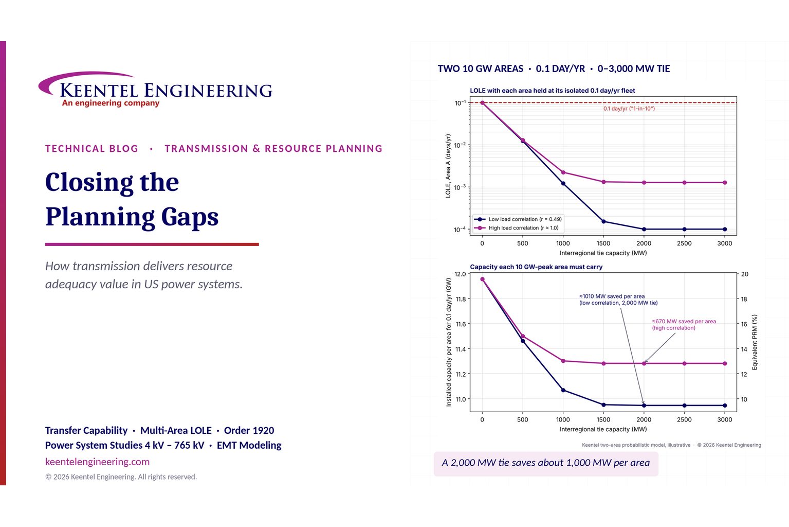
Transmission planning and resource adequacy analysis showing LOLE reduction and interregional transf
By SANDIP R PATEL • November 6, 2026
Learn how transmission planning improves US resource adequacy through LOLE, reserve sharing and FERC Order 1920 analysis from Keentel Engineering.
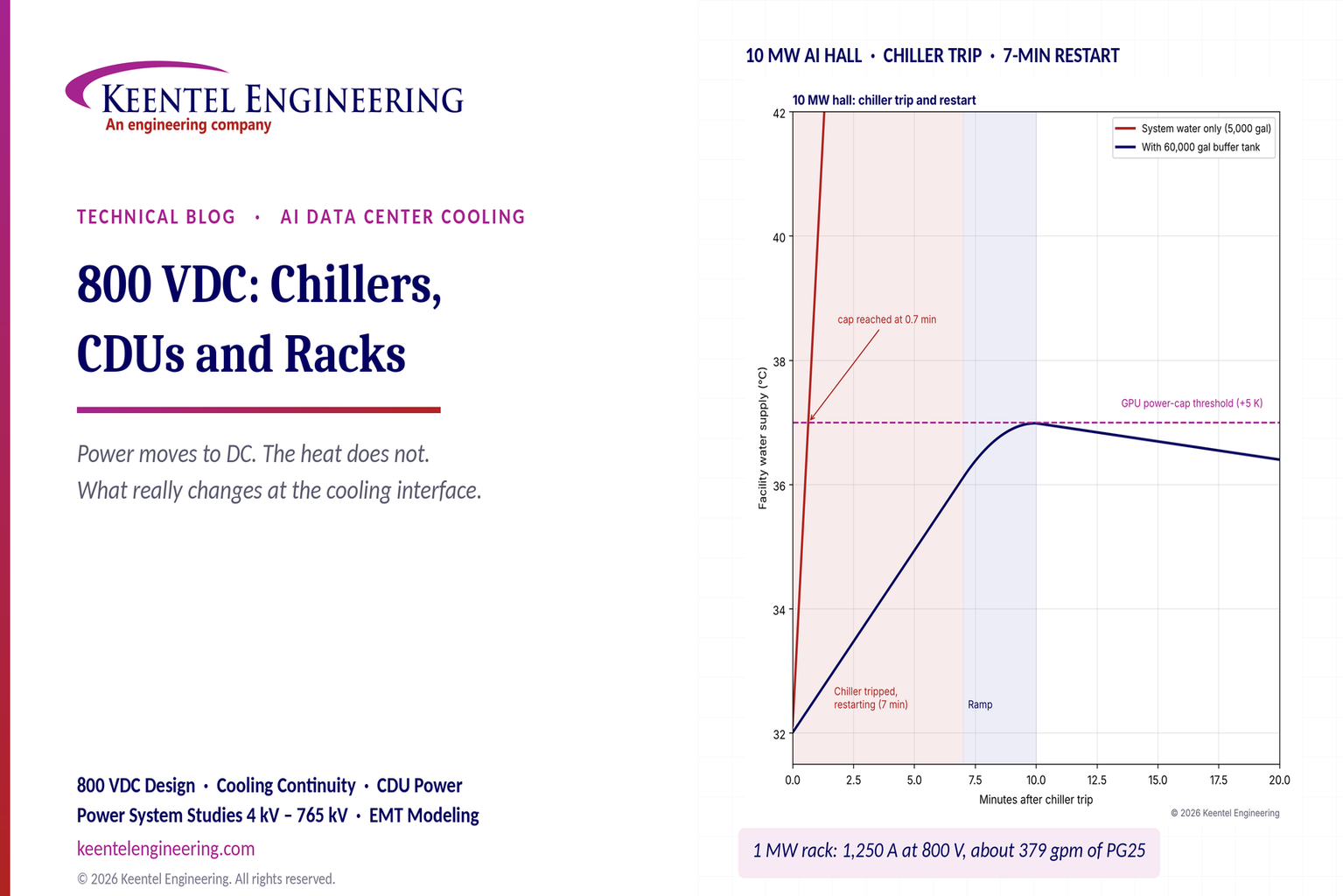
800 VDC AI data center cooling and chiller restart temperature comparison chart.
By SANDIP R PATEL • November 5, 2026
Learn how 800 VDC affects AI data center cooling, including chillers, CDUs, liquid-cooled racks, pump backup and DC safety. Keentel Engineering, USA.
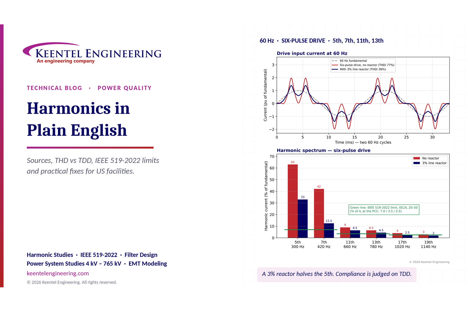
Keentel Engineering harmonics analysis showing current waveforms, harmonic spectrum, and IEEE 519-20
By SANDIP R PATEL • November 5, 2026
Understand electrical harmonics, THD vs TDD and IEEE 519-2022 limits. Keentel Engineering explains US harmonic studies, equipment risks and mitigation.
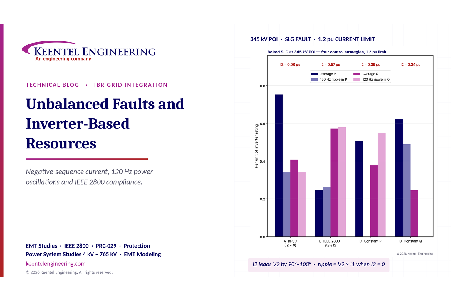
Unbalanced faults in inverter based resources with IEEE 2800 compliance analysis
By SANDIP R PATEL • November 5, 2026
Keentel Engineering explains unbalanced faults in inverter-based resources, negative-sequence current, 120 Hz power oscillations and IEEE 2800 compliance.
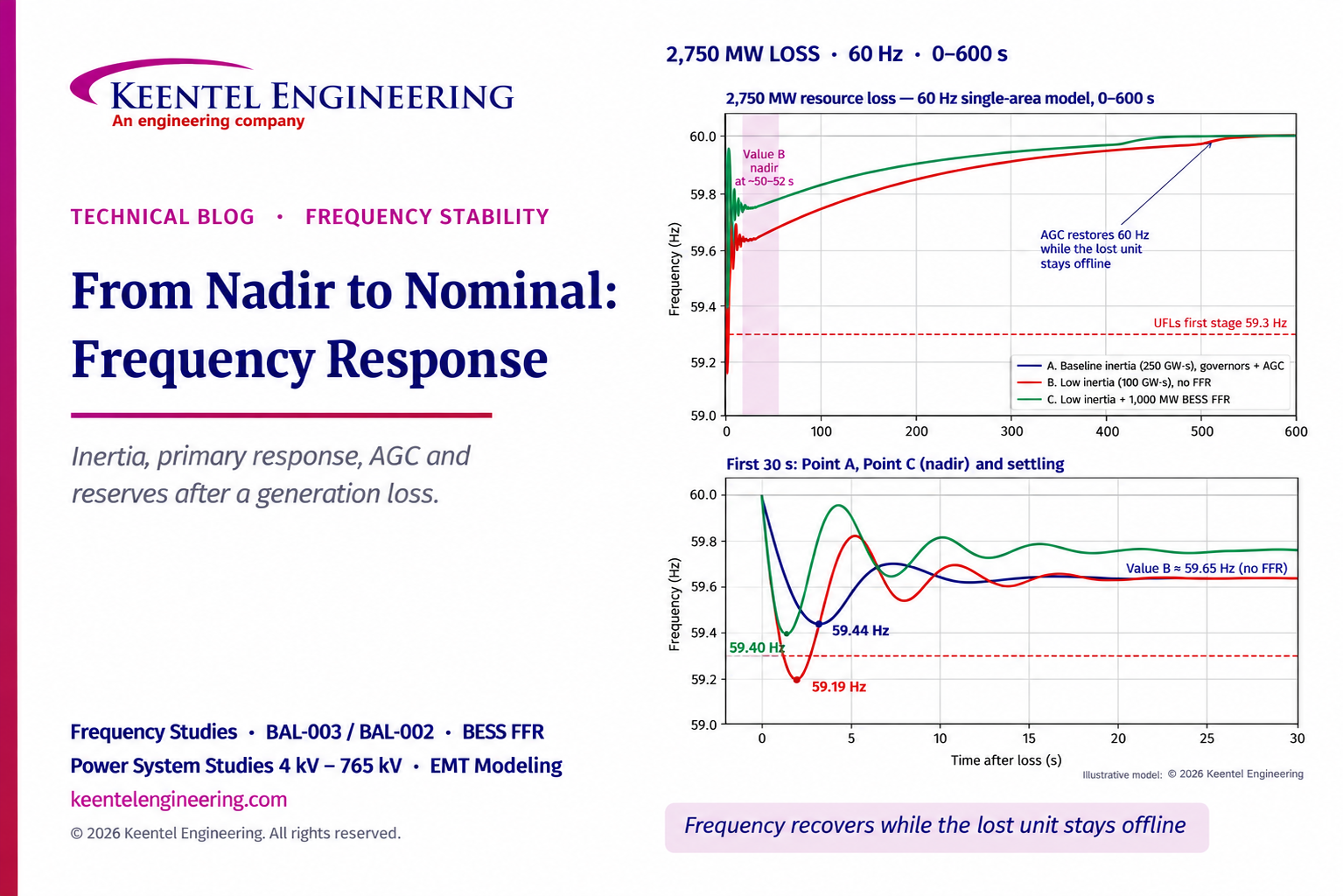
Frequency response curves showing grid stability after a 2,750 MW generation loss.
By SANDIP R PATEL • November 5, 2026
Explore four stages of US grid frequency recovery after generation loss, from inertia and primary response to AGC and reserves, with Keentel Engineering.
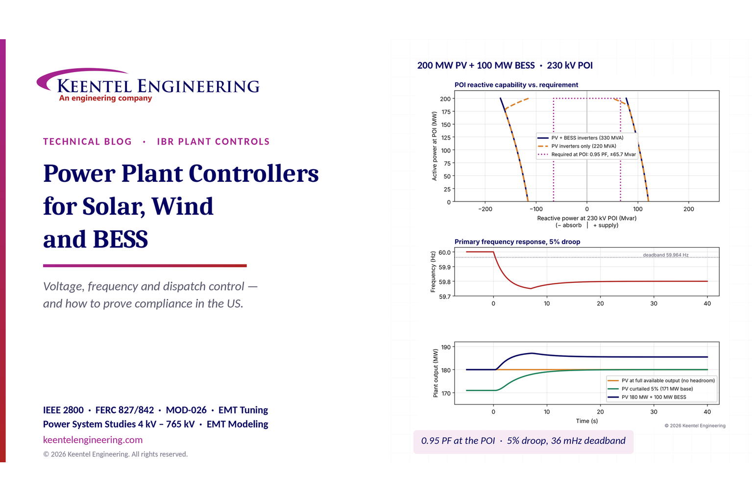
Power plant controller voltage and frequency response for solar, wind and BESS
By SANDIP R PATEL • November 5, 2026
Explore power plant controllers for US solar, wind and BESS with Keentel Engineering. Learn voltage control, frequency response, dispatch and grid compliance.
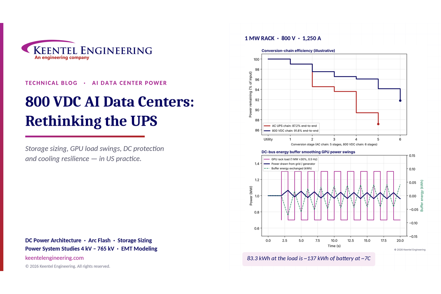
800 VDC AI Data Centers: UPS & Battery Storage | Keentel Engineering
By SANDIP R PATEL • November 5, 2026
Explore 800 VDC AI data center design with Keentel Engineering. Learn UPS architecture, battery sizing, DC protection, arc flash and cooling resilience.
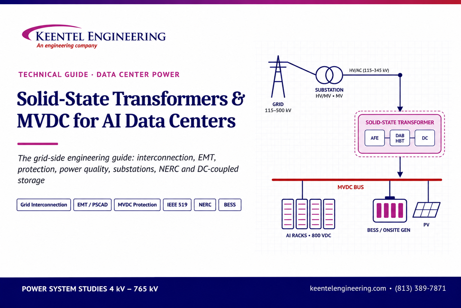
Keentel Engineering solid-state transformer and MVDC power system for AI data centers.
By SANDIP R PATEL • November 5, 2026
Explore solid-state transformers and MVDC for AI data centers. Keentel Engineering covers US grid interconnection, EMT modeling and protection studies.