
A Coordinated Electric System Interconnection Review—the utility’s deep-dive on technical and cost impacts of your project.
Challenge: Frequent false tripping using conventional electromechanical relays
Solution: SEL-487E integration with multi-terminal differential protection and dynamic inrush restraint
Result: 90% reduction in false trips, saving over $250,000 in downtime
ERCOT enforces all of the above through simulation, which means your model is your compliance case. The bar is now high:
- Whole-facility scope. The model must represent everything the IT load, the UPS and power conversion, the cooling plant, the protection and control systems in formats compatible with ERCOT's study platforms (PSS/E, PSCAD, TSAT).
- Real control loops, not approximations. Generic textbook representations are unacceptable. The model must capture the actual inner control behavior of your power electronics.
- Hardware-validated converter models. For electronic loads, the PSCAD model must be benchmarked against actual hardware testing including voltage ride-through and subsynchronous response. A model assembled from standard PSCAD library blocks fails by definition, because a generic block has never been tested against your vendor's hardware. The good news: validation is a hardware-type test, so results for a given converter product are reusable across every facility that uses it.
- Format migration. Facilities that previously submitted the older composite load model (CMLD) format must transition to EPRI's PERC1 format.
- Three checkpoints. Models are reviewed before the stability study begins (no model, no study), before each quarterly stability assessment, and for electronic loads one final time before energization, when you must submit as-built models with a documented comparison against the previously studied data and a sworn attestation that the model matches actual field settings. ERCOT's review takes 10 business days, extendable by 20 put it on your critical path.
- A living obligation. Change your technology, controls, or relay settings in a way that affects ride-through including converting a crypto mining site to an AI data center — and you've triggered a new interconnection study, even if your megawatts don't change.
| Parameter | Detail |
|---|---|
| System | 230 kV / 138 kV transmission corridors, wind and wet-snow icing exposure |
| Data basis | 15 years of minute-resolution forced-outage records + regional weather observations |
| Core methods | Event grouping, MVA performance curves, time-to-95%-restore, area outage rate curves, fragility modeling, rerun-history benefits, exceedance and log-domain risk metrics |
| Headline result | ≈85% of maximum resilience benefit at 60% of original capital; worst-event restoration window cut from 11 days to 5 in rerun-history terms |
| Decision supported | Capital portfolio selection; resilience plan filing; post-investment verification framework |
| System / Topic | Governing Standard(s) | What It Controls |
|---|---|---|
| Overall plant electrical distribution | IEEE 141 (Red Book); IEEE 666 | Distribution architecture, voltage selection, design of generating station auxiliary service systems |
| Power system studies | IEEE 399 (Brown Book); IEEE 551 | Load flow, symmetrical/asymmetrical short circuit, motor starting methodologies down to the lowest LV panelboard |
| Protection & coordination | IEEE 242 (Buff Book); IEEE 3004.5; IEEE C37 series | Generator relaying (21, 59N, 87G), time-current coordination, selective clearing between LV and MV tiers |
| GSU / UAT / SST transformers | IEEE C57.12.00 and C57 family | Transformer ratings, impedance, testing, loading |
| HV switchyard breakers | IEEE C37.06 | AC high-voltage circuit breaker preferred ratings |
| MV switchgear (13.8 kV) | IEEE C37.20.2; IEEE C37.20.7 | Metal-clad construction, compartmentalization, vacuum breakers; arc-resistant design with plenum venting |
| MV cable | UL 1072; ICEA S-93-639 (NEMA WC 74) | Type MV-105 shielded cable, 133% insulation level for HRG systems |
| LV switchgear (480 V) | IEEE C37.13; UL 1558 | Metal-enclosed LV power circuit breaker switchgear to 635 V, draw-out ACBs with electronic trip units |
| Motor control centers | UL 845; NEMA ICS 18 | LV-MCC construction, MCCB/MCP protection for motors under ~200 HP |
| Motors | NEMA MG-1 | Motor performance, starting characteristics, service factors |
| DC & battery systems | IEEE 485; IEEE 946 | Lead-acid battery sizing (125/250 VDC), DC auxiliary system design |
| Grounding | IEEE 80; IEEE 142 (Green Book) | Ground grid step/touch potential limits; system grounding including high-resistance grounding |
| Lightning protection | IEEE 998 | Direct-stroke shielding of switchyard and outdoor generator structures |
| Arc flash & electrical safety | IEEE 1584; NFPA 70E | Incident energy calculation; worker safety boundaries and PPE |
| Fire protection | NFPA 850 | Fire protection and risk management for combustion turbine generating plants |
| Installation code | NEC (NFPA 70); NESC | Wiring methods inside the plant fence; overhead/outdoor clearances at the switchyard |
| Interconnection & compliance | FERC LGIP; NERC MOD-025/026/027, PRC-019/024/029, FAC-008 | Interconnection process, model validation, protection/ride-through coordination, facility ratings |
| IFC / Construction Deliverable | Purpose |
|---|---|
| Stamped IFC packages | Legal basis for construction; P.E. responsible charge |
| Final relay settings & TCCs | Protection as-installed matches the coordination study |
| Calculation archive | Owner records; NERC audit evidence trail |
| Commissioning procedures | Safe, sequenced energization; MOD field testing |
| Construction support | RFIs, field changes, FAT/SAT witness |
| As-builts & model handoff | Operating baseline; future study currency |
| Metric | Outcome |
|---|---|
| Defects found pre-occupancy | Three topology defects and one settings-mismatch family corrected before load migration; the shared-switchboard defect alone would have invalidated the concurrently-maintainable claim on day one |
| IST findings | Fourteen additional discrepancies surfaced under scenario testing (control logic, alarm mapping, one generator sequencing fault) — all closed before handover instead of during operations |
| Black-building test | Passed on second execution; the first attempt exposed the generator sequencing fault under true block load, exactly the failure the compressed plan would never have found |
| Handover quality | Operations team certified on the actual failure scenarios; corrected EOPs and settings documentation delivered as controlled documents |
| Business outcome | Occupancy proceeded three weeks behind the original date — against an independent estimate that the uncorrected sequencing fault carried a high probability of a full facility outage within the first year |
Part 2 — Frequently Asked Questions: Large Load Interconnection
An electric grid must remain in continuous balance — generation onto the grid must equal consumption from it at every instant. PJM achieves this balance, and prices it, through a layered market architecture. Each layer operates on a different time horizon, and each one touches project economics differently.
| Domain | Key Standards / Codes | What They Govern |
|---|---|---|
| Fire safety | NFPA 855; UL 9540 / UL 9540A | Installation requirements, separation, gas management; system safety listing and thermal-runaway fire testing |
| Grid interconnection | IEEE 1547 (distribution); IEEE 2800 (transmission IBRs) | Ride-through, reactive capability, power quality, and performance at the point of interconnection |
| Power quality | IEEE 519 | Harmonic distortion limits at the PCC |
| Protection & grounding | IEEE 80 / 81 / 142; C37 series | Grounding system design and testing; protective relaying |
| Reliability compliance | NERC standards (incl. PRC ride-through requirements) | Registered-entity obligations for grid-connected storage |
| Standard | Current edition | Voltage range |
|---|---|---|
| IEC 60502-2 | Ed. 3.0:2014 + AMD1:2024 | 6 kV to 30 kV (U_m 7.2–36 kV) |
| IEC 60840 | Ed. 5.0:2020, consolidated Ed. 5.1:2023 | above 30 kV to 150 kV (U_m 36–170 kV) |
| IEC 62067 | Ed. 3.0:2022 | above 150 kV to 500 kV (U_m 170–550 kV) |
Solar Plant Electrical Testing: The Fourteen Tests, and the Four That Actually Find the Fire
Aug 17, 2026 | Blog
A Keentel Engineering Grid IQ technical guide for commissioning engineers, owner's engineers, EPC quality managers, and utility cable asset owners
Introduction: Plants Are Being Handed Over 4.46% Down
The standard solar commissioning graphic lists fourteen electrical tests: insulation resistance, continuity, earth resistance, earth continuity, polarity, string open-circuit voltage, short-circuit current, I-V curve, transformer tests, HT cable tests, relay testing, breaker testing, CT/PT testing, and inverter testing. Underneath it says test before energization — safety, reliability and performance first.
All fourteen are real tests, and the list is a fair scope summary. But it obscures the finding that ought to reshape how the industry thinks about acceptance testing.
Aerial thermographic survey data across a cumulative fleet of roughly 373 GW-dc puts average power loss at commissioning at 4.46%, against a 2025 fleet-wide average of 5.08%. In other words, plants are being handed over carrying nearly the same anomaly burden as plants that have been operating for years. The gap between "commissioned" and "correct" is now measurable — and it is small, which means most of a plant's lifetime underperformance is baked in before commercial operation.
The fourteen tests are not catching it.
There are three reasons, and this guide is organized around them:
The tests that would find the most expensive defects are all optional. Cross-mated DC connectors — a leading cause of PV fires — pass every mandatory test in the commissioning standard. Insulation defects that only conduct when wet pass every dry insulation resistance test; a peer-reviewed study published in January 2026 found 13.5% of field-aged modules were "dry-pass / wet-fail." Sub-amp ground faults pass every fuse-based ground-fault detector. The tests that catch these three — Category 2 thermography, the wet insulation test, and documentary connector QA — are, respectively, conditional, an "additional test," and not an electrical test at all.
The acceptance criteria are mostly not in the standards. The insulation resistance table is normative.
Almost nothing else is. The 5% band on Voc, the I-V curve pass/fail, the capacity test threshold — all of it is contractual practice, and the standards say so explicitly. One of them states in as many words that determining acceptable results "is beyond the scope of this test method."
The rulebook changed underneath the industry in eighteen months, and a great many specifications have not caught up.
Part 1 — What the Sequence Is Actually For
Between July 2024 and 2026, four foundational documents governing US solar electrical testing changed or are changing:
| Document | What happened |
|---|---|
| ANSI/NETA ECS-2024(3rd edition, ANSI-approved 2 July 2024) | Added a Photovoltaic Systems commissioning section, alongside new UPS and automatic transfer switch sections |
| ANSI/NETA ATS-2025(ANSI-approved 20 February 2025) | Added Section 7.29, Solar Photovoltaic Systems — and Section 7.28 for BESS |
| NFPA 70E next edition | Adds a new PV-specific article with explicit DC arc flash thresholds |
| IEC 62446-1 Edition 2 | Cleared DIS approval, at or near FDIS stage as of mid-2026 |
The first two matter enormously and are almost unremarked. Until 2024, utility-scale solar in the United States had no native ANSI-approved acceptance or commissioning specification — only the IEC document, written primarily around European practice and around systems much smaller than a 300 MW single-axis tracker plant. Now it has both: ATS-2025 for equipment acceptance and ECS-2024 for the commissioning process.
Every ATS Section 7 subsection follows the same three-part structure — visual and mechanical inspection, electrical tests, and test values — so §7.29 gives US practice a familiar framework for PV that maps onto how the rest of a
substation is already specified. If your solar commissioning specification predates February 2025, it does not reference either document, and it should.
1.1 Which code even applies?
This is the first question on any utility-scale solar project and it is answered wrong more often than any other.NEC 90.2(B) excludes from NEC scope installations under the exclusive control of an electric utility that are on property owned or leased by the utility for the purpose of generation, transformation, transmission, distribution or metering. A solar plant owned and operated by a regulated utility on utility land is therefore outside NEC scope and is designed to the NESC (ANSI C2).NEC Article 691, "Large-Scale Photovoltaic (PV) Electric Supply Stations," exists precisely to cover the gap. Its scope covers facilities with a generating capacity of no less than 5,000 kW that are not under exclusive utility control — the IPP and merchant plant that sells into the grid but is not a utility.
What Article 691 actually does is frequently overstated. It does not blanket-exempt Article 690. It substitutes engineered, PE-stamped, independently verified design for several prescriptive requirements:
- 691.5 permits approval by engineering review where listed and labeled products do not exist — a genuine relief valve for utility-scale hardware
- 691.9 permits isolating devices located more than 6 ft from the equipment they isolate where written safety procedures exist, and relieves buildings housing only PV equipment from rapid shutdown
- 691.10 permits a documented fire-mitigation plan where DC arc-fault protection is not provided
- 691.6 and 691.7 make all of it contingent on stamped documentation and stamped independent engineering conformance reports available to the AHJ before commercial operation
It also imposes requirements: Qualified-personnel-only operation, restricted access with fencing per 110.31, interconnection through medium- or high-voltage switchgear or a substation, loads limited to generation auxiliaries, and — a sentence worth knowing — large-scale PV electric supply stations shall not be installed on buildings.
Rapid shutdown does not apply to a ground-mounted utility-scale plant: For three independent reasons: 690.12 by its own title and scope reaches only circuits on or in buildings; 691.4 prohibits these stations from being on buildings at all; and 691.9 expressly substitutes written system shutdown procedures available at the station site.
The practical consequence for commissioning: On a single site you can have the array, DC system and collection system under NEC 690/691 up to the point of change of ownership, and the substation, GSU and interconnection under NESC. Which rule set applies where is a jurisdictional and contractual determination, not a technical one — and it needs to be settled in the specification, not argued at inspection.
One 2026 NEC change large-scale designers should note:
The 100 kW threshold has been removed from 690.7(A)(3) and 690.8(A)(1)(a)(3). A licensed electrical engineer may now use engineering calculation methods for a PV system of any size, where previously the method was restricted to systems at or above 100 kW. There is also a new alternative at 690.8(A)(1)(a)(2) permitting calculation per the module manufacturer's instructions — aimed squarely at bifacial modules, where the old Isc × 1.25 rule does not describe reality.
Part 2 — The Fourteen Tests, Rewritten
Test 1 — Insulation resistance
The normative table. IEC 62446-1 Table 2 gives the only hard numeric acceptance criteria in the whole commissioning standard, keyed to system voltage defined as Voc(STC) × 1.25:
| System voltage | Test voltage | Minimum insulation resistance |
|---|---|---|
| < 120 V | 250 V DC | 0.5 MΩ |
| 120 V to 500 V | 500 V DC | 1 MΩ |
| > 500 V | 1000 V DC | 1 MΩ |
Now look at what that means on a 1500 V plant: The code-minimum acceptance value is 1 MΩ. A healthy new 1500 V array reads tens to hundreds of megohms. A string that "passes" at 1.5 MΩ has passed the standard and failed engineering — it is a defect report, not an acceptance.
This is the single most important reframing in this guide: The IEC table is a safety floor — the value below which the array is dangerous. It is not a quality criterion. A commissioning specification that adopts it as the acceptance criterion has adopted a threshold that essentially no defect can fail.
What to specify instead: a floor well above the IEC minimum (many owner's engineers use tens of megohms as an investigation trigger on 1500 V systems), plus string-to-string comparison — the outlier matters more than the absolute value — plus archival of every reading as the baseline the inverter's insulation monitoring device will be judged against for the next thirty years.
Method 1 versus Method 2: The standard offers two:
- Test method 1 — test between array negative and earth, followed by a test between array positive and earth.
- Test method 2 — test between earth and short-circuited array positive and negative.
The difference is not cosmetic Method 2 requires a short-circuiting device rated for the full array short-circuit current and system voltage — you are deliberately creating a bolted short on a current source that cannot be switched off. Method 1 avoids that, at the cost of two measurements and twice the connection operations on a live DC circuit.
Diagnostically, Method 1 localizes the fault to a pole; Method 2 returns only the parallel combination of the positive and negative resistances. Practical guidance: Method 2 for speed on clean commissioning batches, Method 1 the moment anything reads low.
Conduct the test in low irradiance and dry conditions, measure Voc first, and discharge array capacitance afterwards.
An instrument trap worth flagging. Most handheld commissioning test sets top out at 1000 V insulation test voltage and 1000 V Voc measurement — which is fine for a 1000 V system and insufficient for the 1500 V arrays that dominate utility-scale construction. Verify the instrument's voltage ratings against the actual array before mobilizing. This catches teams out regularly.
Test 2 — Continuity
IEC 62446-1 does not state a bare current figure. It achieves the requirement by reference: the standard requires instruments compliant with IEC 61557, and IEC 61557-4 requires a continuity test current of at least 200 mA at an open-circuit voltage of 4 V to 24 V.
A 200 mA continuity test is a continuity test, not a fault-current-withstand test. It confirms a conductive path exists. It says nothing about whether that path will survive a fault, and on a utility-scale plant with kilometres of bonded tracker rows, mechanical grounding lugs and exothermic connections, that distinction matters.
Which is why most owner's engineers additionally specify high-current bonding tests (10 A or 25 A) on a sampled basis, plus separate grounding-grid testing at the substation. Those are practice, not IEC requirements — write them in.
Tests 3 and 4 — Earth resistance and earth continuity
The earth resistance test on a solar plant is the same engineering problem as on any substation, and it is subject to the same widespread misconception: IEEE Std 80's acceptance criteria are step and touch voltage limits, not a grid resistance value. The commonly specified "1 ohm" or "5 ohm" figures are rules of thumb that appear nowhere in IEEE 80 as requirements.
The correct question is whether the measured grid impedance, combined with the actual available fault current and clearing time, keeps computed step and touch potentials below tolerable limits for the surfacing installed — and whether the measured impedance matches the design model.
For the fall-of-potential measurement, the 61.8% rule derives from a uniform-soil, hemispherical-electrode idealization that a real grid violates. Require the full traverse, plotted, with a visible plateau — and expect the remote current electrode at five to ten times the maximum grid diagonal.
(One currency note for anyone writing a grounding specification: IEEE Std 80-2013 was moved to Inactive-Reserved in March 2024, with a revision project active. A great many specifications cite it as current.)
On the array side, the continuity test is checking something structurally different: that module frames, racking, tracker torque tubes and the equipment grounding conductor form a continuous bonded system across thermal expansion joints, tracker bearings and slip joints. Tracker rotation is the enemy — bonding jumpers across rotating and sliding joints are a recurring construction defect and a recurring inspection finding.
Test 5 — Polarity
Verify polarity of every DC circuit — modules, source circuits, output circuits, disconnects, inverter input terminations — before closing any disconnect. A reversed string in a combiner is a classic commissioning finding, and it will destroy string fuses or blocking components on first energization.
The thing polarity testing does
not catch is the defect described in Part 3: a connector mated to the correct polarity, from the wrong manufacturer.
Test 6 — String open-circuit voltage
Voc is the workhorse field measurement, and understanding why is worth two paragraphs.
Voc depends only weakly (logarithmically) on irradiance, and strongly, linearly and predictably on temperature. Above roughly 200 W/m² you can measure it accurately without a calibrated pyranometer. It is the single best detector of module-count errors, missing or shorted modules, shorted bypass diodes, and reversed modules.
The arithmetic:
Voc(T_cell) = N_modules × Voc(STC) × [1 + β × (T_cell − 25 °C)]
where β is the temperature coefficient of Voc in %/°C, and is negative.
A note on β values, because the commonly quoted range is now out of date. The −0.27 to −0.35 %/°C band that appears in most references is correct for older p-type PERC modules. Modern n-type TOPCon is materially better — −0.24 to −0.27 %/°C is now typical, and heterojunction is better still. A current n-type utility module datasheet gives β = −0.25 %/°C, α (Isc) = +0.045 %/°C, and γ (Pmax) = −0.29 %/°C. Using a legacy β on a modern module will produce an expected Voc that is systematically wrong, and the error runs in the direction of failing good strings on hot days.
Worked example: Twenty-eight modules in series, Voc(STC) = 53.3 V, β = −0.25 %/°C:
- At a cell temperature of 48 °C: 28 × 53.3 × [1 + (−0.0025)(23)] ≈ 1,406 V
- At −10 °C on a winter morning: 28 × 53.3 × [1 + (−0.0025)(−35)] ≈ 1,623 V
That second number is the string-sizing calculation, and it is over 1500 V — which is exactly the point NEC 690.7 addresses and exactly the reason cold-weather string length is a design decision, not a construction one.
Acceptance. IEC 62446-1 is deliberately comparative rather than absolute here — it requires comparison against expected and against sibling strings without publishing a hard number. The ±5% band is the near-universal industry interpretation, quoted consistently across manufacturer guidance and the SolarPower Europe best-practice guidelines, which also require Voc and Isc measurement on 100% of strings and correction to actual cell temperature rather than STC.
Test 7 — Short-circuit current
Isc scales essentially linearly with in-plane irradiance and only weakly with temperature:
Isc(G, T) ≈ Isc(STC) × (G / 1000) × [1 + α × (T_cell − 25)]
At α ≈ +0.045 %/°C, a 40 °C temperature excursion moves Isc by under 2%. Irradiance moves it proportionally.
Which is exactly why Isc is the weaker field measurement, and why it should be treated differently from Voc:
- It inherits the full uncertainty of the irradiance measurement. A 3% pyranometer error is a 3% Isc error, directly. Reference cell versus thermopile, spectral mismatch, angle-of-incidence error, soiling on the sensor itself, misalignment to the array plane — all of it lands on Isc.
- Irradiance is non-stationary. A 1–2% drift during the measurement is invisible to the operator and fully present in the result.
- Soiling is indistinguishable from irradiance error in an Isc reading. Both depress the curve uniformly.
- Bifacial modules break the simple relationship entirely. Rear-side irradiance is spatially non-uniform and varies with albedo, row position and height, and is rarely measured well.
- The measurement is itself a hazard. IEC 62446-1 permits an operational (in-service) current test as an alternative to a true short-circuit test, for exactly this reason.
Practical guidance: treat Voc as a pass/fail measurement and Isc as a comparative measurement. String-to-string consistency — within roughly 5% of the array mean under stable irradiance — is far more meaningful than absolute agreement with a datasheet.
Test 8 — I-V curve
This is where the diagnostic value lives, and where most commissioning campaigns underuse the data they already paid to collect.
The first screen is fill factor: FF = (Imp × Vmp) / (Isc × Voc). Typical crystalline silicon runs 0.75–0.85; thin film 0.55–0.75.
The five deviation classes and what each one physically is:
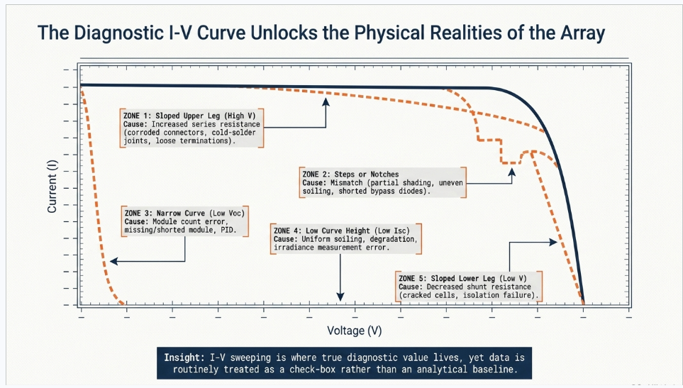
| Curve signature | Region | Physical cause |
|---|---|---|
| Sloped upper leg — tilt inward near Voc | High-voltage | Increased series resistance — cracked cell interconnects, corroded connectors, cold-solder joints, undersized or over-long conductors, loose terminations |
| Sloped lower leg — tilt down near Isc | Low-voltage | Decreased shunt resistance — cell edge-isolation failure, cracked cells, manufacturing shunts, PID |
| Steps or notches | Anywhere | Mismatch — partial shading, uneven soiling, cracked cells, shorted bypass diodes, mixed module types, differential aging. Step width is proportional to the number of affected cell strings |
| Low curve height (low Isc) | Whole curve depressed | Uniform soiling, edge soiling, irradiance measurement error, encapsulant browning, delamination, degradation |
| Narrow curve (low Voc) | Whole curve narrowed | Module count error, missing or shorted module, failed bypass diodes, elevated cell temperature, PID |
A decision tree that works in the field: Is the shape normal? If no, look for steps and notches — that is mismatch. If yes, is the curve short (low Isc), narrow (low Voc), or both? If the dimensions are normal, compute fill factor; a low FF sends you to Vmp/Voc (low implies series resistance) and to the slope of the Isc leg (steep implies shunt resistance).
Voltage-deficit arithmetic is a genuinely useful trick: If the Voc deficit equals one module's Voc, a module is missing or shorted. If it is smaller, individual cell strings are being bypassed — a 60-cell module's bypass diode spans 20 cells, roughly one-third of module Voc. Two adjacent shaded cells in the same cell-string drop the voltage by roughly one-sixth; one shaded cell in each of two cell-strings roughly doubles that drop.
Measurement conditions are what make or break a campaign:
- Minimum irradiance 400 W/m², preferably above 600–700 W/m²
- Test within the four-hour window centred on solar noon, clear sky
- Irradiance stability: a 1–2% change during the sweep produces questionable data; a change above 10% mimics a major array failure. Cirrus is the enemy — irregular variation plus cloud-edge magnification
- Wind low — wind changes module temperature mid-sweep
- Irradiance sensor: in the plane of array, a reference cell of similar technology designed for backside mounting, not a thermopile pyranometer, to minimize spectral and angle-of-incidence error
- Temperature sensor: on the back centre of the module — edges run cooler, and edge-to-centre variation can reach ±15 °C
And one trap that is genuinely under-appreciated: sweep rate on high-capacitance cells High-efficiency architectures — interdigitated back contact, heterojunction — have substantially higher cell capacitance, and the sweep rate should not exceed roughly 10 V per second per cell. Sweep too fast and the capacitance produces an apparent series-resistance signature that is a measurement artefact, not a defect. Teams have condemned perfectly good modern modules this way.
Translation to STC. IEC 60891:2021 Edition 3 provides four correction procedures the classical linear superposition method (Procedure 1), a simplified one-diode model with non-linear irradiance scaling (Procedure 2), interpolation between measured curves requiring no fitting parameters (Procedure 3), and a new Procedure 4 that determines series resistance from a single I-V curve, valid between 300 and 1200 W/m² for crystalline silicon.
The acceptance fight in an EPC contract is almost never about the measurement. It is about which IEC 60891 procedure and which Rs, κ, α and β values were used to translate to STC. Specify the procedure by number in the test plan — it prevents a category of dispute that costs weeks.
Note that neither IEC 62446-1 nor IEC 61829 publishes a numeric I-V pass/fail. Any threshold in your specification is contractual.
Test 9 — Transformer tests
The graphic lists "IR, winding resistance, TTR, vector group and more," which is right. The current governing documents are worth stating precisely, because most solar specifications cite superseded editions:
- IEEE C57.12.00-2021 — general requirements. Turns ratio must be within ±0.5% of calculated, on all taps, with vector group and phase relationship verified
- IEEE C57.12.90-2021 — test code
- IEEE C57.152 — field diagnostic testing. (The 2013 edition, which most specifications cite, moved to Inactive-Reserved in March 2024)
- IEEE C57.149-2024 — sweep frequency response analysis, superseding the 2012 edition. SFRA on arrival, before the unit is set, is the only practical field method for detecting winding displacement in transit
- IEEE C57.104-2019 — dissolved gas analysis, using a percentile-based Status 1/2/3 framework stratified by transformer age and oxygen-to-nitrogen ratio, having replaced the older condition/TDCG scheme
Two solar-specific points. Collection-system transformers are cycled hard — energized at sunrise, de-energized at sunset, every day, for thirty years — so inrush duty, no-load loss and tap changer duty deserve more attention than on a conventional load-serving transformer. And the factory test report must travel with the unit, with per-bushing power factor and capacitance, winding resistance per tap at a stated temperature, and the SFRA baseline. A site result that cannot be compared to a factory value corrected to the same temperature is a number, not a result.
Test 10 — HT cable tests
Medium-voltage collection cable is the highest-value cable testing scope on a solar plant, and the standards moved recently:
| Standard | Current edition |
|---|---|
| IEEE 400 — field testing of shielded power cable systems | 400-2023 |
| IEEE 400.1 — HVDC, laminated dielectric only | 400.1-2018 |
| IEEE 400.2 — very low frequency (VLF) | 400.2-2024 |
| IEEE 400.3 — partial discharge field diagnostic testing | 400.3-2022 |
Three points that matter on a solar collection system specifically:
DC hipot is the wrong test for extruded cable. IEEE 400.1's title restricts it to laminated dielectric — PILC, pipe-type, pressurized. On XLPE and EPR, DC stress traps space charge that does not redistribute at 60 Hz and superimposes on the AC field, and on service-aged cable it can convert benign water trees into electrical trees. Use VLF or 20–300 Hz resonant AC.
The sheath integrity test belongs before backfill. It is the only after-installation test that finds pulling damage, rock in the trench bed and tool strikes — and on a solar site with tens of kilometres of directly buried collection cable installed at pace, that is the dominant damage mechanism. IEC 60229 Clause 5 specifies 4 kV DC per mm of oversheath thickness, capped at 10 kV, for one minute, with the metallic layer negative. The "10 kV" everyone quotes is the cap, not a flat value.
Convert the withstand to a monitored withstand.
Published evaluation of cable diagnostics found failure-on-test rates of roughly 2.0% at 15 minutes, 2.7% at 30 minutes and 3.7% at 60 minutes — so roughly half the defects a 60-minute test finds are invisible at 15 minutes. Recording tan delta and partial discharge during the same energization costs one instrument connection and no additional outage, and turns "the circuit survived" into "the joint in run 14 has a defect."
Test 11 — Relay testing
IEEE C37.233-2023 is the current guide for power system protection testing, superseding the 2009 edition that nearly every specification still cites.
The test hierarchy, and what each layer uniquely catches:
- Secondary injection — per-element pickup, dropout, timing and characteristic verification. Catches settings that do not match the approved file.
- Primary injection — proves the whole current path from CT primary through secondary wiring to the relay input. Nothing else catches a swapped CT lead or a shorting screw left in.
- Functional trip check — every relay output actually trips the intended breaker through all interposing auxiliaries, by actual breaker operation, not by jumpering.
- End-to-end testing — GPS-synchronized injection at both terminals for line differential and pilot schemes.
On a solar plant, add: anti-islanding and transfer trip scheme verification, directional element polarity verification (a solar plant is a source, and directional elements set for a load-serving feeder will be wrong), and verification that the settings implement the interconnection agreement's ride-through requirements rather than the relay vendor's defaults.
Structure the commissioning record so it can serve as the first PRC-005 maintenance record if the plant is BES-jurisdictional. Building it in the wrong format means re-creating it later.
Test 12 — Breaker testing
Timing per pole and pole scatter, trip and close coil current signatures, minimum pickup voltage of trip and close coils, contact resistance, and insulation resistance pole-to-pole, pole-to-ground and across open contacts. Manufacturer data governs the limits.
The acceptance criterion worth knowing for contact resistance: compare against manufacturer's published range first, and where none exists, investigate values deviating by more than 50% of the lowest value in the comparison set — the lowest, not the average. For poles reading 45, 48 and 70 µΩ, the threshold is 45 × 1.5 = 67.5 µΩ, so the 70 µΩ pole is investigable.
For SF₆ equipment, IEEE C37.122.3-2024 covers gas handling, superseding the 2011 edition. And on any new solar substation, the SF₆ question is now a procurement question — California prohibits acquisition of new SF₆ gas-insulated equipment on a schedule already in force below 145 kV, and New York adopted a comparable schedule in December 2024.
Test 13 — CT and PT testing
IEEE C57.13-2016 governs, with C57.13.1 for field testing of relaying CTs. Field acceptance covers ratio at all taps, polarity, excitation/saturation curve, winding resistance, burden and insulation.
The item most often misunderstood: relaying accuracy class notation is a burden capability statement, not a percentage. All ANSI relaying classes require ratio error within ±10% from 1× to 20× rated secondary current. The numeric suffix is the secondary terminal voltage the CT delivers at 20× rated secondary current without exceeding that error — so a C400 CT delivers 400 V at 100 A, meaning a 4 Ω burden capability. The letter matters too: C means the error can be calculated from the excitation curve, T means it must be determined by test, K adds a guaranteed knee point at not less than 70% of the secondary terminal voltage rating.
And do not interchange knee points. The ANSI 45° knee and the IEC knee (a 50% voltage increase producing a 10% current increase) are different points, and the IEC one is higher. Substituting one for the other in a relay setting review is a real and recurring error.
Polarity errors on CT secondaries invert differential and directional protection — producing a relay that behaves perfectly under secondary injection and trips backwards on a real fault. Confirm by DC flick test: momentary DC into P1–P2, deflection direction observed at S1–S2.
Test 14 — Inverter testing
"Verifies DC input, AC output, protection, alarms and grid synchronization" is a fair summary of the functional scope, and radically understates the compliance scope.
Which framework applies depends on where you interconnect:
- Distribution-connected: IEEE 1547.1-2020 specifies type, production, commissioning and periodic tests confirming conformance to IEEE 1547. Its Clause 8 defines four distinct commissioning evaluation paths depending on whether the reference point of applicability is the point of connection or the point of common coupling, and whether the DER is a unit or a composite. Which path applies is a decision to make in the specification, not on site.
- Transmission-connected: IEEE 1547 does not automatically apply. The governing requirements come from the interconnection agreement, the FERC LGIA, IEEE 2800-2022, and the applicable NERC standards — principally PRC-024 and PRC-029 for ride-through and protection settings, plus MOD-026 and MOD-027 for model verification.
That last item deserves emphasis, because it is where solar projects most often get caught. The compliance risk has shifted from equipment capability to model fidelity and test evidence. An inverter platform that is fully capable of the required ride-through behaviour will still fail a compliance review if the EMT model does not reproduce that behaviour with the settings actually loaded at the site, validated in combination with the plant controller. Commissioning is where that evidence is either created or lost.
Functional scope that belongs in every inverter commissioning plan regardless: DC input verification against the string configuration; MPPT tracking verification; AC output and power quality; protection settings against the approved file; voltage and frequency ride-through verification; volt-var, volt-watt and frequency-watt response curves; anti-islanding; reconnection timing; alarm point-to-point to SCADA; and communications to the plant controller with setpoint response verified end to end.
Part 3 — The Four Tests That Actually Find the Fire
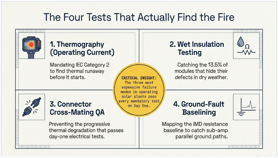
Here is the uncomfortable structural fact about the standard fourteen-test list: the three most expensive failure modes in operating solar plants all pass every mandatory test.
3.1 Thermographic inspection — conditional, and it shouldn't be
IEC 62446-1 makes I-V curve measurement and infrared thermographic inspection Category 2 tests — required for larger and more complex systems, but triggered by size and complexity rather than by a MW threshold, and therefore in practice invoked contractually. On utility-scale work they should be mandatory, and SolarPower Europe's best-practice guidance calls for 100% module thermography at commissioning.
IEC TS 62446-3:2017 is the governing document, and it is far more prescriptive than most people who commission aerial IR realize.
Measurement conditions:
- Irradiance ≥ 600 W/m² in the plane of the module
- For electrical balance-of-system components, ≥ 30% of rated system current
- Wind max 4 Bft / 28 km/h
- Cloud max 2 okta of cumulus
- Low or no soiling; cleaning recommended
- Ambient air temperature measured and documented, equipment accuracy ±2 K
Camera requirements:
- NETD ≤ 0.1 K at 30 °C
- Spectral band 8–14 µm for general use
- Geometric resolution: max 3 cm of module edge per pixel, and minimum 5×5 pixels per 6-inch cell
- Absolute error < ±2 K, traceable calibration at least every two years
- Radiometric image storage required, so absolute temperatures can be recovered later
That radiometric storage requirement is worth writing into a specification explicitly. A JPEG of a hot spot is a picture. A radiometric file is evidence.
| Class | Definition | Required action |
|---|---|---|
| 1 | No abnormality | No imminent action |
| 2 | Thermal abnormality | Check cause; rectify within a reasonable period |
| 3 | Safety-relevant thermal abnormality | Prompt interruption of operation, check cause, rectify |
Representative ΔT examples (from the informative annex — these are examples, not universal thresholds): a module in open circuit runs 2–7 K above its neighbours; a single-cell hot spot is Class 2 at 10–40 K and Class 3 above 40 K; a heated junction box is Class 2–3 at ≥ 3 K versus a nearby junction box; a transfer-resistance (connection) defect is Class 2–3 above 10 K.
Irradiance extrapolation matters because you rarely inspect at exactly the reference condition: ΔT₂ = (G₂/G₁)^x · ΔT₁, with exponent x = 1.5 for point abnormalities in modules, 1.6 for BOS, and 1.0 for extended-area abnormalities.
Reporting requirements include personnel names and qualifications, camera make/model/serial, environmental conditions including cloud in okta and irradiance in W/m², the emissivity and reflected temperature used, and each finding located by at least two independent methods — serial number, photograph, X-Y coordinates, permanent marking.
The standard recommends a four-year periodic interval. Utility-scale owner practice is typically annual, and increasingly continuous via docked autonomous drones — and the field data supports it: sites using autonomous docked drones show 3.0% average power loss against 5.08% for the rest of the fleet, with quarterly inspection associated with a 36% improvement and five or more inspections a year with a 119% improvement.
3.2 Wet insulation resistance — an "additional test," and the data says it shouldn't be
The dry insulation resistance test finds gross faults: a damaged cable jacket against a rail, a pinched conductor, a compromised junction box. It does not find micro-cracks in backsheets, marginal junction-box seals, or connector seals that conduct only when wet.
A peer-reviewed study published in January 2026 quantified the gap, testing 37 field-aged crystalline silicon modules dry (1000 V DC, two minutes) and wet (per the module qualification wet leakage method):
| Result | Value |
|---|---|
| Median dry resistance | 42.4 GΩ |
| Median wet resistance | 462.5 MΩ |
| Median ratio | ≈ 110× |
| Modules that passed dry and failed wet | 5 of 37 — 13.5% |
| Overall wet-failure rate | 21.6% (8 of 37), five of them catastrophic |
The authors conclude that dry-only testing is insufficient to guarantee safety, and propose a conservative dry screening threshold to flag modules needing wet verification.
Where this shows up in operations: intermittent inverter insulation-monitoring trips that correlate with morning dew and rain — the classic "it only faults when it's foggy" ticket — plus accelerated PID and corrosion-driven degradation.
On acceptance criteria, the US standard is refreshingly honest. ASTM E2047, the wet insulation integrity test method for PV arrays, states: "This test method does not establish pass or fail levels. The determination of acceptable or unacceptable results is beyond the scope of this test method." The user must specify the minimum acceptable value. Wet insulation acceptance is always a contractual choice — so make it deliberately rather than by omission.
A practical middle ground short of a full wet test: run the commissioning insulation test early morning while dew is still on the array, and again dry, and compare. Any string with an anomalous dry-to-wet ratio is a defect report. That costs one extra pass and finds a category of defect that a dry-only campaign cannot.
3.3 Connector cross-mating — not an electrical test at all
This is the defect that passes every test in the standard.
Connectors from different manufacturers may physically mate while having dimensionally different contact geometries, spring-band designs and sealing profiles. The result is elevated contact resistance at the interface, which produces I²R heating, which degrades the polymer housing and seal, which admits moisture, which drives corrosion, which raises resistance further. The failure is progressive and thermally self-reinforcing, which is why it kills years after commissioning rather than at energization.
Prevalence. Roughly 3.5 billion PV connections exist globally, and connectors are described by module testing laboratories as a leading cause of fires instigated by PV systems in many markets. In a large sample of US distributed-generation system inspections, well over half of inspected systems contained safety issues requiring immediate attention, with 40% of urgent safety issues involving field-made or factory-made connectors.
The standards paradox. NEC 690.33 requires that where mating connectors are not of identical type and brand, they shall be listed and identified for intermatability per the manufacturer's instructions. UL 6703 (and its IEC counterpart IEC 62852) theoretically permits evaluated intermatability. But major connector manufacturers' published installation instructions explicitly prohibit cross-mating — and because NEC 110.3(B) mandates compliance with listing instructions, the manufacturer's prohibition supersedes any generic listing in the field. In practical terms, no truly universal PV connector exists.
What a cross-mated connector reads on day one: normal Voc, normal Isc, normal insulation resistance, normal I-V curve. Every mandatory test passes.
It is found only three ways: documentary QA of the bill of materials and connector types at design stage; visual inspection at installation; and thermographic inspection at operating current — which is precisely why the IEC 62446-3 thresholds of ≥3 K on junction boxes and >10 K on transfer-resistance defects exist, and precisely why Category 2 thermography should not be optional.
3.4 The ground-fault detection blind spot
DC ground-fault protection on PV is required for circuits above 30 V or 8 A, and its purpose is fire prevention, not personnel shock protection.
Historically it was implemented as a fuse or breaker of 0.5 to 4 A in the grounded-conductor-to-ground bond inside transformer-isolated inverters. Ground faults in an array are frequently under 1 A — below any of those thresholds. Residual-current detectors typically need on the order of 300 mA or more, and fuse-based schemes often require several amps to blow.
The failure mode. An undetected first fault on the grounded conductor sits invisibly. A second fault elsewhere creates a parallel path that bypasses the detector entirely, allowing large current to flow through racking, module frames and conductors — producing arcing, melted conductors and fire.
The canonical case. Documented in the industry literature: a 383 kW rooftop array where an initial fault of roughly 2.5 A went undetected because it sat below the detector's trip threshold. When a roof expansion joint later separated, a 311 A fault developed and routed through the pre-existing small fault, producing a rooftop fire.
Why this belongs in a commissioning article. Modern transformerless inverters use insulation monitoring devices that measure array-to-ground resistance continuously and trip on a resistance threshold rather than on fuse current. That is a much better protection scheme — and it depends entirely on knowing what "normal" looks like.
Your commissioning insulation resistance data is the baseline that device is judged against for the life of the plant. Recorded properly — per string, with irradiance, temperature and instrument identified — it is the reference dataset for every subsequent ground-fault investigation. Recorded as a tick in a box against a 1 MΩ floor, it is worthless.
Part 4 — DC Arc Flash: Why the Conservative Assumption Is the Wrong One
DC arc flash on PV is genuinely different from AC arc flash, and the industry has been getting it wrong in a direction that surprises people.
A PV array is a current-limited source. It cannot supply unbounded fault current, and the operating point during an arc slides into the non-linear region of the I-V curve depending on irradiance. NREL's measurement work found arc voltages sitting at 10–40% of the I-V maximum power voltage — far below the normal operating point. In one test, 26.7 kW was available at maximum power but only 3.7 kW was delivered during arcing, a factor of about seven.
The consequence: the maximum-power method in NFPA 70E's informative annex overestimates PV incident energy by factors of five to ten versus measurement. Comparisons across calculation methods show 5–70% deviations depending on the method chosen; one commonly used empirical model with standard coefficients overestimated by 33–71%.
Why over-estimating is not "conservative." It drives PPE selection upward, and in a desert solar field in July, heavy arc-rated PPE introduces heat-stress and dexterity hazards that are themselves a real injury mechanism. A calculation that is wrong by 7× in the safe direction has traded one hazard for another without anyone deciding to.
NREL's recommendations are a double-iterative model combining the PV I-V characteristic with arc equations — single-diode models are adequate, within about 5% — and the observation that the industry needs a DC analogue to IEEE 1584.
And the code is moving. NFPA 70E's next edition adds a new article specific to photovoltaic systems, with the committee statement that it "addresses the unique electrical hazards associated with work practices on PV installations." The published first-revision material sets explicit thresholds: a DC arc flash hazard boundary at 150 volts and 1.2 cal/cm², with work on exposed PV terminals exceeding those thresholds prohibited, and manipulation of connectors requiring a risk assessment that determines maximum open-circuit voltage and current-interrupting capability before energized operation.
(Confirm the article number and publication status against the published edition — trade summaries and NFPA's own revision documents disagree on numbering.)
That connector clause is worth pausing on. It effectively makes "pull the connector and see" a prohibited troubleshooting method on a plant above those thresholds, which is exactly how a great deal of string troubleshooting is currently done.
Part 5 — Capacity, Performance Ratio and Availability Are Three Different Tests
The fourteen-test list stops at energization. The tests that determine whether the EPC gets paid come after, and conflating them is the single most common cause of solar EPC disputes.
| Capacity test | Performance ratio test | Availability test | |
|---|---|---|---|
| Question | Can the plant produce its rated power at defined reference conditions? | How efficiently does it convert available sunlight to delivered energy over time? | What fraction of the time could it produce when it should have? |
| Standard | ASTM E2848 + E2939, or IEC TS 61724-2:2025 | IEC 61724-1:2021 (PR = Yf / Yr); IEC TS 61724-3 for energy | No published test standard — contractually defined |
| Duration | ASTM: ~5–7 clear days, often 2–4 weeks elapsed. IEC Ed. 2: 3–5 days | Typically one year; short-form 7–15 day tests used at provisional acceptance | Continuous |
| Isolates | Plant capability, weather-normalized | Plant + weather + availability + soiling + degradation | Uptime only |
| Belongs in | EPC contract — the substantial completion gate | O&M contract, or the EPC's 1–2 year performance guarantee | O&M contract |
A capacity test isolates what the EPC built. A PR test measures what the plant delivers — which includes weather, soiling, curtailment, grid outages and O&M quality, none of which the EPC controls after handover. Curtailment and grid-driven unavailability must be explicitly carved out of both, or you are penalizing the EPC for the offtaker's behaviour.
The ASTM pair and how they divide the work. ASTM E2939 determines the anticipated capacity at a specific location and sets the reporting conditions — irradiance, ambient temperature, wind speed. ASTM E2848 measures against them. You cannot run a defensible capacity test with one and not the other. (E2848 is currently under revision — a work item is open, which means the dominant US capacity test method is actively moving.)
The data filtering rules decide the outcome more than the measurement does. Typical practice excludes plane-of-array irradiance below 400 W/m²; excludes data where inverter output exceeds 98% of nameplate (clipping); keeps only data within roughly ±20% of the reporting-condition irradiance; constrains the distribution so no more than a 40/60 split sits above and below; excludes snow, frost, beam shading and any period where the inverter is not tracking maximum power; and requires on the order of 500 filtered data points at one-minute resolution.
IEC TS 61724-2 went to Edition 2 in September 2025, and it closes the gap that causes most modern disputes. It is retitled to include a power performance index — measured power over expected power at test conditions — it explicitly accounts for high DC:AC ratios, clipping and curtailment (the 2016 edition assumed unconstrained operation), it is adapted for bifacial systems, it shortens the test to three to five days, and it leans on PV modelling software for expected power rather than pure on-site regression.For a US audience, ASTM remains the dominant contractual method while IEC 61724-2 is more common on internationally financed projects — but the 2025 revision closes the clipping gap that ASTM has not yet closed, which is a genuine reason for US independent engineers to look at it on high DC-ratio plants.
On acceptance thresholds, be careful. No standard sets a capacity test pass threshold. ASTM E2848 provides a method, not a criterion. Published contractual examples cluster around 95–97% of modelled capacity for a pass, with liquidated damages commonly indexed from a 98% reference — but every one of those numbers is negotiated, not standardized.
And the statistical treatment is worth more than the threshold. Sophisticated contracts do not compare point estimates; they require the upper confidence bound of the measured capacity to meet or exceed the guaranteed capacity — which allocates measurement uncertainty explicitly. Whether that uncertainty falls on the EPC or the owner is a negotiated term, and on a large plant it can be worth more than the entire liquidated damages schedule.
Part 6 — Three Anonymized Case Studies
Confidentiality note. The three engagements below are presented in anonymized and generalized form. No client, developer, EPC, utility, location, vendor or date is identified, and capacities, configurations, sequences and findings have been altered or aggregated. They are included to illustrate recurring engineering and commercial patterns, not to characterize any single project.
Case Study A — The Plant That Passed Every String Test and Ran 4% Down
Situation. A large single-axis tracker plant completed commissioning with a full IEC 62446-1 Category 1 test campaign: continuity, polarity, combiner verification, Voc and Isc on 100% of strings, functional tests, and insulation resistance on every string. The test records were complete and legible, every string passed, and the plant was accepted. Within the first operating year the owner's monitoring showed production consistently below the model by a margin large enough to matter but small enough to be argued about. We were engaged to determine whether the shortfall was a build defect or a model error.
What the review found. The test campaign had been executed competently and had answered a narrower question than the owner believed.
- The insulation resistance acceptance criterion was the IEC table minimum. Every string was recorded as "pass, >1 MΩ." A number of strings had in fact been recorded at values in the low tens of megohms — perfectly compliant, and dramatically lower than their neighbours. Because the criterion was a floor rather than a comparison, nobody had looked at the distribution. Re-analysis of the raw commissioning data showed a clear population of outliers clustered in specific blocks.
- Voc and Isc had been recorded but not analyzed as a population. Both were checked against a ±5% band string by string. No string-to-string statistical comparison had been performed, so a systematic depression across one inverter block — well inside the 5% band on any individual string — was invisible.
- Thermographic inspection had not been performed at commissioning. It was in the specification as a Category 2 item, and had been deferred to the first annual inspection on schedule grounds.
- No I-V curve data existed at all.The first aerial thermographic survey, conducted after we recommended it, found a population of module-level and string-level anomalies concentrated in the blocks that the insulation resistance re-analysis had already flagged.
Outcome and lessons. The defects were remediated under warranty, but a year of production had been lost and the commercial position was weaker than it would have been at handover.
Four transferable lessons:
- The IEC insulation resistance table is a safety floor, not a quality criterion. On a 1500 V array a 1 MΩ pass threshold is a test essentially no defect can fail. Specify a working floor far above it, and — more importantly — specify string-to-string comparison as the acceptance mechanism.
- Commissioning data has to be analyzed as a dataset, not as a stack of pass/fail sheets. The information required to find these defects was already in the records. Nobody had plotted it.
- Do not defer Category 2 thermography. Aerial IR at commissioning is cheap relative to what it finds, and it is the only test that catches thermal defects — including connector defects — which pass every electrical test.
- The commissioning record is a baseline or it is nothing. Recorded per string with irradiance, temperature and instrument identity, insulation resistance data becomes the reference against which the inverters' insulation monitoring is judged for thirty years. Recorded as a tick against a floor, it has no forward value.
Case Study B — The Capacity Test That Could Not Be Settled
Situation. A plant with a high DC-to-AC ratio reached substantial completion and the contractual capacity test was run. The EPC's analysis showed a pass. The owner's independent engineer's analysis of the same data showed a fail. Both parties had used the same standard, the same measured data and the same modelling package. We were engaged to determine the source of the divergence.
What the review found. Four separate methodological choices, none of them specified in the contract, each of which moved the result by a meaningful margin — and which compounded in the same direction:
- Clipping treatment. The plant's DC-to-AC ratio meant a significant fraction of clear-sky midday data was clipped. The test method the contract named was written on the assumption of unconstrained operation. The two parties had adopted different filtering rules for clipped points, and that choice alone accounted for the largest part of the divergence.
- The reporting-condition irradiance band. The contract did not specify the acceptable window around the reporting-condition irradiance. One party used a narrow band, the other a wide one, and the two datasets had materially different compositions.
- Which regression terms were retained. The wind term's statistical significance was marginal. Retaining or dropping it changed the fitted capacity.
- Uncertainty allocation. The contract stated a guaranteed capacity and a measured capacity, and said nothing about confidence bounds. One party compared point estimates; the other compared the lower confidence bound of the measurement against the guarantee.
None of the four choices was unreasonable. All four were unspecified.
Outcome and lessons. The dispute was settled by agreeing a re-test under a jointly written test procedure that fixed every one of those choices in advance. The re-test took three weeks of clear weather to schedule and delayed final acceptance by a quarter.
Four transferable lessons:
- Write the test procedure into the contract, not the standard's name. "Capacity test per ASTM E2848" is not a specification. The procedure must fix the filtering rules, the irradiance band, the regression form and the treatment of statistically insignificant terms.
- Clipping is the single biggest source of capacity-test dispute on modern plants, and the older methods do not address it. IEC TS 61724-2's 2025 edition explicitly handles high DC:AC ratios, clipping and curtailment, and is worth evaluating on any high-ratio plant even where ASTM is the contractual default.
- Allocate measurement uncertainty explicitly. Whether the confidence bound falls in the owner's or the EPC's favour is a negotiated term, and on a large plant it can be worth more than the liquidated damages schedule.
- Carve out curtailment and grid unavailability in writing. They belong to nobody's performance and they will otherwise be argued about twice — once in the capacity test and once in every subsequent performance ratio calculation.
Case Study C — The Connector Nobody Tested For
Situation. An operating plant experienced a localized fire in the array field. There were no injuries. The owner engaged us as part of the technical investigation and to review whether the failure mode was present elsewhere on the site.
What the review found. The proximate cause was a DC connector interface that had failed thermally: elevated contact resistance had driven progressive heating, degrading the housing and seal, admitting moisture, driving corrosion, and raising resistance further until the interface arced. The connector had been in service for several years.
Two findings mattered more than the individual failure:
- The bill of materials showed connectors from more than one manufacturer in the same circuits, without documentation establishing that the specific combinations were listed and identified for intermatability. The module-side and harness-side connectors physically mated, so nothing in installation flagged them.
- The commissioning records were complete and showed no anomaly. Voc, Isc, insulation resistance and continuity had all been within specification for the affected circuits. Every mandatory test had passed, and every one of them would pass again on a cross-mated interface on day one, because contact resistance at commissioning current is too small to register in any of those measurements.
A subsequent thermographic survey at operating current, conducted specifically to look for the signature, identified a population of interfaces running hot relative to their neighbours.
Outcome and lessons. The affected interfaces were remediated and the connector specification was revised for the owner's remaining pipeline.
Four transferable lessons:
- Connector intermatability is a documentary control, not a test. It must be caught in design review and procurement — the specification should name the connector type and require that all mating interfaces be from the same manufacturer, or that documented listed intermatability exists for the specific combination.
- The manufacturer's instruction governs. Where a connector manufacturer's published instructions prohibit cross-mating, the code requirement to install per listing instructions makes that prohibition binding regardless of any generic listing. In practice this means treating universal intermatability as unavailable.
- Thermographic inspection at operating current is the only field test that finds this. Not at open circuit, not at low current — at operating current, with the resolution and ΔT thresholds the thermography standard specifies. The relevant thresholds are on the order of ≥3 K for a junction box and >10 K for a transfer-resistance defect.
- A clean commissioning record is not evidence that a plant is free of this failure mode. It is evidence that the tests performed do not detect it. That distinction is worth understanding before it is explained by an investigator.
Part 7 — A Commissioning Specification Checklist
Framework and scope
- Applicable code stack decided and stated — NEC 690/691 versus NESC, by system area
- ANSI/NETA ATS-2025 §7.29 and ECS-2024 PV sections referenced explicitly, alongside IEC 62446-1
- IEC 62446-1 Category 2 mandated — I-V curve and thermography, not optional
- Clause 8 additional tests specified: wet insulation resistance, string voltage to ground, blocking diode, shade evaluation
DC array
- Insulation resistance acceptance criterion set well above the IEC table minimum, plus string-to-string comparison as the primary mechanism
- Insulation test method (1 or 2) specified, with the short-circuiting device rating stated if Method 2
- Instrument voltage ratings verified against the actual array — 1500 V, not 1000 V
- Voc acceptance band and temperature correction method specified, with the module's actual β
- Isc specified as a comparative test with a stated statistical criterion, and an operational current test permitted in lieu of short-circuit
- I-V curve measurement conditions specified: minimum irradiance, solar-noon window, irradiance stability limit, sensor type and mounting, temperature sensor location, and sweep rate limits for high-capacitance modules
- IEC 60891 translation procedure specified by number, with the Rs, κ, α and β values to be used
Thermography
- 100% module thermography at commissioning, per IEC TS 62446-3
- Camera specification stated: NETD, spectral band, cm-per-pixel, pixels per cell, calibration currency
- Radiometric image storage required as a deliverable
- Classes of Abnormality adopted as the acceptance framework, with ΔT thresholds and the irradiance extrapolation exponents
- Findings located by at least two independent methods
Balance of plant
- MV cable: VLF or resonant AC (not DC on extruded), monitored withstand, sheath test before backfill
- Transformer: factory test report travels with the unit; SFRA on arrival before setting
- Protection: primary injection and functional trip checks by actual breaker operation; directional element polarity verified for a source, not a load
- Inverter: applicable framework identified (IEEE 1547.1 path, or interconnection agreement / IEEE 2800 / NERC), with model validation evidence as a deliverable
Safety
- DC arc flash study using a PV-appropriate method, not the maximum-power assumption
- Connector intermatability documented at design stage and verified at installation
- Commissioning record format specified — per test: instrument and calibration date, conditions, technician, criterion and its source, measured values, comparison baseline, disposition
Part 8 — Frequently Asked Questions
Q: What insulation resistance value should I accept on a 1500 V array?
Not the IEC 62446-1 table value. That table gives 1 MΩ minimum at a 1000 V test voltage for systems above 500 V, and it is a safety floor — the threshold below which the array is dangerous — not a quality criterion. A healthy new 1500 V string reads tens to hundreds of megohms. Specify a working floor far above the code minimum, and make string-to-string comparison the primary acceptance mechanism: the outlier matters more than the absolute number. Then archive every reading as the baseline the inverter's insulation monitoring device will be judged against for the life of the plant.
Q: Should I use insulation test Method 1 or Method 2?
Method 2 (short positive and negative together, test to earth) is faster but requires a short-circuiting device rated for the full array short-circuit current and system voltage — you are deliberately creating a bolted short on a source that cannot be switched off. Method 1 (negative to earth, then positive to earth) avoids the shorting device but doubles the connection operations on a live DC circuit. Diagnostically, Method 1 localizes a fault to a pole; Method 2 gives only the parallel combination. Use Method 2 for speed on clean batches and Method 1 the moment anything reads low. Whichever you specify, state the shorting device rating requirement explicitly.
Q: Why does my test set say 1000 V when my array is 1500 V?
Because most handheld commissioning test sets were designed around the 1000 V market and have not all followed the industry to 1500 V. Common ratings are 1000 V maximum insulation test voltage and 1000 V maximum Voc measurement — which means the instrument cannot even measure a fully cold 1500 V string, let alone test it. Verify instrument voltage ratings against the actual array before mobilizing. This is one of the most common practical traps in utility-scale commissioning.
Q: What temperature coefficient should I use to calculate expected Voc?
The one on the specific module's datasheet — and check it, because the commonly quoted range is out of date. The −0.27 to −0.35 %/°C band in most references describes older p-type PERC modules. Modern n-type TOPCon typically runs −0.24 to −0.27 %/°C, and heterojunction better still. Using a legacy value on a modern module produces a systematically wrong expected Voc, and the error runs in the direction of failing good strings on hot days. Isc coefficients are more stable, around +0.04 to +0.06 %/°C.
Q: Why is Voc a better field measurement than Isc?
Because Voc depends only logarithmically on irradiance and linearly and predictably on temperature, while Isc scales directly with irradiance. That means Isc inherits the full uncertainty of your irradiance measurement — a 3% pyranometer error is a 3% Isc error — plus any irradiance drift during the measurement, plus any soiling on the sensor, plus spectral and angle-of-incidence error. Soiling on the array is also indistinguishable from irradiance error in an Isc reading. And bifacial modules break the relationship entirely, because rear-side irradiance is spatially non-uniform and rarely well measured. Treat Voc as a pass/fail measurement and Isc as a comparative one.
Q: Do I have to short-circuit strings to measure Isc?
No. IEC 62446-1 permits an operational (in-service) current test as an alternative to the short-circuit test, precisely because deliberately shorting a live string is a hazard. On utility-scale plants the operational test at a combiner, with strings clamped one at a time under stable irradiance, gives you the same comparative information with far less risk — and it simultaneously finds reversed strings, open strings, blown fuses and severe soiling.
Q: What irradiance do I need for a valid I-V curve measurement?
A practical minimum of 400 W/m², preferably above 600–700. But irradiance stability matters more than magnitude: a 1–2% change during the sweep produces questionable data, and a change above 10% mimics a major array failure. Test within the four-hour window centred on solar noon under clear sky, with low wind. Cirrus is the worst condition — it produces both irregular variation and cloud-edge magnification. Mount the reference sensor in the plane of array, use a reference cell of similar technology rather than a thermopile pyranometer, and put the temperature sensor on the back centre of the module, since edges run cooler by as much as 15 °C.
Q: My high-efficiency modules show high series resistance on the I-V trace. Are they defective?
Check the sweep rate first. High-efficiency architectures — interdigitated back contact, heterojunction — have substantially higher cell capacitance, and the sweep rate should not exceed roughly 10 V per second per cell. Sweeping faster produces an apparent series-resistance signature that is entirely a measurement artefact. Teams have condemned good modern modules this way. Slow the sweep and re-measure before writing a defect report.
Q: How do I read an I-V curve deviation?
Start with fill factor — FF = (Imp × Vmp) / (Isc × Voc), typically 0.75–0.85 for crystalline silicon. Then: a sloped upper leg near Voc means increased series resistance (cracked interconnects, corroded connectors, loose terminations); a sloped lower leg near Isc means decreased shunt resistance (cracked cells, edge isolation failure, PID); steps or notches mean mismatch (shading, soiling, shorted bypass diodes), with step width proportional to the number of affected cell strings; a low curve means reduced Isc (soiling, irradiance error, degradation); a narrow curve means reduced Voc (module count error, missing or shorted module, failed bypass diodes, PID). The voltage-deficit arithmetic is useful: a deficit equal to one module's Voc means a module is missing or shorted; a smaller deficit means bypass diodes are conducting, and a 60-cell module's diode spans roughly one-third of module Voc.
Q: Which IEC 60891 correction procedure should the test plan specify?
Specify one by number. Edition 3 (2021) offers four: Procedure 1 (classical linear superposition, requiring Rs, α, β and a curve correction factor), Procedure 2 (simplified one-diode model with non-linear irradiance scaling, not recommended where shunt resistance is low), Procedure 3 (interpolation between measured curves, requiring no fitting parameters and most accurate when interpolating rather than extrapolating), and Procedure 4 (new in Edition 3, determining series resistance from a single curve, valid 300–1200 W/m² for crystalline silicon). The acceptance dispute in an EPC contract is almost never about the measurement — it is about which procedure and which parameter values were used to translate to STC. Fix both in the test plan.
Q: Does commissioning testing detect potential-induced degradation?
Essentially no, and it is worth being honest about that. PID develops over months to years through accumulated voltage-hours; at day zero there has been no accumulation. What commissioning can do is establish the baseline — insulation resistance and STC-translated string Pmax — against which future PID is measured, and verify the preventive design features: the inverter grounding scheme, the presence and correct operation of any anti-PID or PID-recovery function, and module PID qualification per IEC TS 62804-1 (Edition 2, 2025). Note that PID qualification only demonstrates degradation stays under a threshold after a specific accelerated stress; it does not guarantee PID will not occur in a particular climate and system-voltage configuration. Also note that PID is a poor infrared target — an aerial IR survey can pass a PID-affected plant, because the temperature gradients are minimal.
Q: Is the wet insulation resistance test worth running?
The data says yes. A January 2026 peer-reviewed study of 37 field-aged crystalline modules found a median dry resistance of 42.4 GΩ against a median wet resistance of 462.5 MΩ — a ratio of about 110× — with 13.5% of modules passing dry and failing wet, and an overall wet failure rate of 21.6%. The authors conclude dry-only testing is insufficient to guarantee safety. Note that ASTM E2047, the US wet insulation test method, states explicitly that it "does not establish pass or fail levels" — acceptance is always a contractual choice, so make it deliberately. A practical middle ground: run the commissioning insulation test early morning with dew on the array and again dry, and flag any string with an anomalous ratio.
Q: Why do my inverters trip on insulation faults only when it is foggy?
Because you have a wet-conducting insulation defect — a micro-cracked backsheet, a marginal junction-box seal, or a compromised connector seal — that presents essentially infinite resistance dry and conducts when wet. Every dry insulation test will pass it. This is the operational signature of the dry-pass/wet-fail population described above, and it is why the wet test exists. It is also why the commissioning insulation dataset matters: without a per-string baseline, you cannot tell which strings have degraded and which were always marginal.
Q: What actually causes PV connector fires, and why does no test find them?
Cross-mated connectors — interfaces where the two halves come from different manufacturers, physically mate, but have dimensionally different contact geometries and sealing profiles. The result is elevated contact resistance, which drives I²R heating, which degrades the housing and seal, which admits moisture, which drives corrosion, which raises resistance further. The failure is progressive and thermally self-reinforcing, so it manifests years after commissioning. On day one, a cross-mated connector reads normal Voc, normal Isc, normal insulation resistance and a normal I-V curve. It is found only by documentary QA at design stage, visual inspection at installation, and thermographic inspection at operating current.
Q: Isn't cross-mating allowed if the connectors are listed?
In theory. NEC 690.33 permits it where connectors are "listed and identified for intermatability," and UL 6703 provides for evaluated intermatability. In practice it is not available, because major connector manufacturers' published installation instructions explicitly prohibit cross-mating — and NEC 110.3(B) requires installation per listing instructions, which makes the manufacturer's prohibition binding. The practical position is that no truly universal PV connector exists, and the specification should require matched connectors from a single manufacturer at every interface, or documented listed intermatability for the specific combination.
Q: Does rapid shutdown apply to a utility-scale ground-mount plant?
No, for three independent reasons. NEC 690.12 by its own title and scope applies to PV system circuits on or in buildings. Article 691 prohibits large-scale PV electric supply stations from being installed on buildings at all. And 691.9 expressly relieves buildings that house only PV equipment from 690.12, substituting written system shutdown procedures available at the station site. Carports, canopies and any building-mounted portion of a project are a different question and need checking against the current article text.
Q: Why does DC ground-fault protection miss faults?
Because the traditional implementation is a fuse or breaker of roughly 0.5 to 4 A in the grounded-conductor bond, and array ground faults are frequently under 1 A. An undetected first fault sits invisibly; a second fault elsewhere then creates a parallel path that bypasses the detector entirely, allowing large current through racking, module frames and conductors. The documented canonical case involved an initial fault of about 2.5 A that went undetected, followed later by a 311 A fault that routed through it and started a rooftop fire. Modern transformerless inverters use insulation monitoring devices that trip on array-to-ground resistance rather than fuse current — which is a much better scheme, and which depends entirely on having a good commissioning baseline to compare against.
Q: Is the NFPA 70E maximum-power method appropriate for PV DC arc flash?
No, and this is a case where the conservative assumption is the wrong one. A PV array is a current-limited source, and NREL measurement work found arc voltages at only 10–40% of the maximum power voltage. In one test, 26.7 kW was available at maximum power but only 3.7 kW was delivered during arcing. The maximum-power method overestimates PV incident energy by factors of five to ten. Over-estimating is not free: it drives PPE selection that introduces heat-stress and dexterity hazards in a desert solar field. Use a PV-appropriate method — a double-iterative model combining the array's I-V characteristic with arc equations. Note also that NFPA 70E's next edition adds a PV-specific article with a stated 150 V and 1.2 cal/cm² DC arc flash threshold, above which work on exposed PV terminals is prohibited and connector manipulation requires a documented risk assessment.
Q: What is the difference between a capacity test and a performance ratio test, and which belongs in the EPC contract?
A capacity test asks whether the plant can produce its rated power at defined reference conditions, weather-normalized — it isolates what the EPC built, and it belongs at the substantial completion gate. A performance ratio test measures how efficiently the plant converts available sunlight to delivered energy over time, which includes weather, soiling, curtailment, grid outages and O&M quality — things the EPC does not control after handover. PR belongs in the O&M contract or in a time-limited EPC performance guarantee. Conflating them is the most common cause of solar EPC disputes, and curtailment and grid unavailability must be explicitly carved out of both.
Q: Why do capacity tests on high DC-ratio plants generate so many disputes?
Clipping. The dominant US method was written on an assumption of unconstrained operation, and modern plants with high DC-to-AC ratios clip a significant fraction of clear-sky midday data. How you filter clipped points, what irradiance band you keep around the reporting condition, whether you retain a statistically marginal wind term, and whether you compare point estimates or confidence bounds — each of those choices moves the answer, and contracts routinely specify none of them. IEC TS 61724-2's 2025 edition explicitly handles high DC:AC ratios, clipping and curtailment, and is worth evaluating even where the ASTM method is the contractual default.
Q: What capacity test threshold should the contract specify?
That is entirely a negotiation — no standard sets one. ASTM E2848 provides a method, not a criterion. Published contractual examples cluster around 95–97% of modelled capacity for a pass, with liquidated damages commonly indexed from a 98% reference, but treat all of those as practice rather than as requirements. More important than the number: specify the full test procedure in the contract (filtering rules, irradiance band, regression form), and allocate measurement uncertainty explicitly — whether the confidence bound falls in the owner's or the EPC's favour can be worth more than the entire LD schedule on a large plant.
Q: Which inverter compliance framework applies to my project?
It depends on where you interconnect. Distribution-connected: IEEE 1547.1-2020 specifies commissioning tests confirming conformance to IEEE 1547, with four distinct evaluation paths depending on whether the reference point of applicability is the point of connection or the point of common coupling and whether the DER is a unit or a composite — pick the path in the specification, not on site. Transmission-connected: IEEE 1547 does not automatically apply; the governing requirements come from the interconnection agreement, the FERC LGIA, IEEE 2800-2022, and applicable NERC standards including PRC-024 and PRC-029 for ride-through and protection settings, and MOD-026/MOD-027 for model verification. On the transmission side the binding constraint is usually model fidelity and test evidence, not equipment capability.
Q: What is the single highest-value change to a typical solar commissioning specification?
Two, and they cost almost nothing. First, make Category 2 mandatory — I-V curve measurement and 100% thermography at commissioning, with radiometric image storage as a deliverable. That is where the defects the electrical tests cannot see are found. Second, require every test result to carry its acceptance criterion and the source of that criterion, alongside the instrument, calibration date, conditions and comparison baseline. A record that says "pass, >1 MΩ" cannot be re-evaluated. A record that says "measured 68 MΩ; criterion: within 20% of block mean (142 MΩ); instrument SN 12345, calibrated 4 months prior; 180 W/m², 14 °C module back" can be defended, audited and trended for thirty years.
Conclusion
The fourteen tests are the right scope. They are not, on their own, an acceptance program.
The acceptance criteria are mostly yours to write:
One numeric table in the commissioning standard is normative, and it is a safety floor that no realistic defect can fail. Everything else — the Voc band, the I-V threshold, the wet insulation limit, the capacity test pass mark — is contractual, and the standards say so explicitly. A specification that names standards without setting criteria has procured a set of measurements, not an acceptance.
The most expensive defects are invisible to the mandatory tests:
Cross-mated connectors, wet-conducting insulation faults and sub-amp ground faults all pass Voc, Isc, insulation resistance and continuity on day one. The three tests that find them — thermography at operating current, wet insulation testing, and documentary connector QA — are conditional, additional and non-electrical respectively. Every one of them is routinely value-engineered out.
And the commissioning record is either a baseline or it is nothing:
The insulation resistance dataset is what the plant's ground-fault protection is judged against for thirty years. The I-V dataset is what degradation is measured from. The thermographic imagery is what next year's survey is differenced against. Recorded properly they are the most valuable engineering asset the plant will ever have. Recorded as pass/fail ticks against a floor, they are a filing obligation.
The data point that should end the argument is the one that opened it:
average power loss at commissioning is 4.46%. Plants are being handed over carrying nearly the full anomaly burden of an operating fleet. That is not a testing technology problem — the instruments and the standards are adequate. It is a specification problem, and it is fixable before the first module arrives on site.
How Keentel Engineering Can Help
Keentel Engineering provides EHV, HV and MV power system engineering to utilities, developers, EPCs, generator owners and public agencies, with offices in Tampa, Austin, Sacramento and Baltimore. Our utility-scale solar practice covers:
- Owner's engineer and independent engineer services — specification development, design review, technical bid evaluation, construction-phase QA, and commissioning package audit
- Commissioning scope development — IEC 62446-1 Category 2 test plans, acceptance criteria with stated basis, thermography specifications, and turnover record format
- Interconnection and POI engineering — feasibility, system impact and facilities studies, POI design support, and large-load and generation interconnection
- Power system studies — short circuit, coordination, arc flash including PV-appropriate DC arc flash analysis, grounding grid design and step/touch potential per IEEE 80, and EMT/PSCAD stability and control-interaction analysis
- Protection and control engineering — setting calculations, settings management, commissioning test plan development, and independent review of commissioning packages
- Performance testing support — capacity and performance ratio test procedure development, independent analysis, and dispute resolution
- NERC compliance support — PRC-024/PRC-029 ride-through compliance, MOD-026/027 model verification, and PRC-005 program structure
- Specification currency review — auditing existing solar and substation testing specifications against current standard editions
References and Further Reading
PV commissioning and testing standards
- IEC 62446-1:2016+AMD1:2018, PV systems — Requirements for testing, documentation and maintenance — Part 1: Grid connected systems — https://webstore.iec.ch/en/publication/24057
- IEC 62446-2:2020, Part 2: Maintenance of PV systems — https://webstore.iec.ch/en/publication/27382
- IEC TS 62446-3:2017, Part 3: Photovoltaic modules and plants — Outdoor infrared thermography — https://webstore.iec.ch/en/publication/28628
- IEC 61829:2015, PV array — On-site measurement of current-voltage characteristics — https://webstore.iec.ch/en/publication/23561
- IEC 60891:2021 Ed. 3.0, Procedures for temperature and irradiance corrections to measured I-V characteristics — https://webstore.iec.ch/en/publication/61766
- IEC 61724-1:2021, PV system performance — Monitoring — https://webstore.iec.ch/en/publication/65561
- IEC TS 61724-2:2025 Ed. 2.0, Power performance index and capacity evaluation method — https://webstore.iec.ch/en/publication/66710
- IEC 62548-1:2023, PV arrays — Design requirements — https://webstore.iec.ch/en/publication/64171
- IEC TS 62804-1:2025 Ed. 2.0, Test methods for the detection of potential-induced degradation — https://webstore.iec.ch/en/publication/71747
- IEC 63027:2023, PV power systems — DC arc detection and interruption — https://webstore.iec.ch/
- ANSI/NETA ATS-2025 (§7.29 Solar Photovoltaic Systems) — https://webstore.ansi.org/standards/neta/ansinetaats2025
- ANSI/NETA ECS-2024, Standard for Electrical Commissioning Specifications — https://www.netaworld.org/
- ASTM E2848-13(2023), Reporting Photovoltaic Non-Concentrator System Performance — https://webstore.ansi.org/standards/astm/astme2848132023
- ASTM E2939-13(2023), Determining Reporting Conditions and Expected Capacity — https://store.astm.org/e2939-13r18.html
- ASTM E2047, Wet Insulation Integrity Testing of Photovoltaic Arrays — https://store.astm.org/e2047-10r19.html
- UL 1699B, Photovoltaic (PV) DC Arc-Fault Circuit Protection — https://webstore.ansi.org/standards/ul/ul1699bed2018
Codes and interconnection
- NFPA 70, National Electrical Code (2026), Articles 690, 691, 705 — https://www.nfpa.org/product/nfpa-70-national-electrical-code-nec/p0070code
- NFPA 70E, Standard for Electrical Safety in the Workplace — https://www.nfpa.org/product/nfpa-70e-standard/p0070ecode
- NFPA 70E A2026 First Revision statements (new PV article; 150 V / 1.2 cal/cm²) — https://docinfofiles.nfpa.org/files/AboutTheCodes/70E/70E_A2026_EEW_AAA_FD_FRStatements.pdf
- IEEE 1547.1-2020, Conformance Test Procedures for Equipment Interconnecting DER — https://standards.ieee.org/standard/1547_1-2020.html
- OSHA 29 CFR 1910.269 — https://www.osha.gov/laws-regs/regulations/standardnumber/1910/1910.269
- EC&M, A New Look at PV Supply Stations (NEC Article 691) — https://www.ecmag.com/section/codes-standards/new-look-pv-supply-stations
Balance-of-plant test standards
- IEEE Std 400-2023 and the 400.x series — https://standards.ieee.org/ieee/400/7618/
- IEEE C57.12.00-2021 / C57.12.90-2021 / C57.152 / C57.149-2024 / C57.104-2019 — https://standards.ieee.org/
- IEEE C57.13-2016, Standard Requirements for Instrument Transformers — https://standards.ieee.org/ieee/C57.13/4867/
- IEEE C37.233-2023, Guide for Power System Protection Testing — https://ieeexplore.ieee.org/document/10258048
- IEEE Std 80, Guide for Safety in AC Substation Grounding — https://standards.ieee.org/ieee/80/4089/
- IEC 60229:2007, Tests on extruded oversheaths with a special protective function — https://webstore.iec.ch/en/publication/1066
Research and field data
- NREL/CP-5K00-78331, Methods for Evaluating DC Arc Incident Energy in PV Systems (2021) — https://docs.nrel.gov/docs/fy21osti/78331.pdf
- NREL/SunSpec, Best Practices for Operation and Maintenance of Photovoltaic and Energy Storage Systems, 3rd ed. — https://sunspec.org/
- Sandia National Laboratories, Recommendations for RCD Ground Fault Detector Trip Thresholds (OSTI 1313068) — https://www.osti.gov/servlets/purl/1313068
- Poulek, Beranek, Finsterle & Kozelka, "Dry Pass, Wet Fail: Ground Impedance Testing of Field-Aged PV Modules," Sustainability, January 2026 — https://doi.org/10.3390/su18031212
- Raptor Maps, 2026 Global Solar Report — https://pages.raptormaps.com/
- Hernday, Field Applications for I-V Curve Tracers (Solmetric / SolarPro) — https://www.solmetric.com/wp-content/uploads/2022/11/SolarPro-FieldApplicationsOf-I-V-Curve-Tracers-Hernday.pdf
- Mayfield Renewables, Mitigating DC Connector Risks in PV Systems — https://www.mayfield.energy/technical-articles/mitigating-dc-connector-risks-in-pv-systems/
- Fluke, DC ground faults in PV systems — https://www.fluke.com/en-us/learn/blog/grounding/dc-ground-faults-pv-systems
- SolarPower Europe,
Solar Best Practices — System Commissioning — https://solarbestpractices.com/guidelines/detail/system-commissionin

About the Author:
Sandip "Sonny" R. Patel, P.E.
IEEE Senior Member · Founder & CEO, Keentel Engineering
In 1995, Sonny Patel earned his Electrical Engineering degree from the University of Illinois. But degrees don't build legacies — action does.
For three decades, he has worked the power industry from every side of the table: 16 years as a utility engineer at Exelon/Commonwealth Edison; generation leadership across hydroelectric, industrial steam turbine, and a 9 GW renewable fleet; NERC Regional Entity Senior Compliance Engineer and Audit Team Lead, auditing some of the nation's largest utilities; and testing and commissioning lead on equipment up to 765 kV — the very top of the North American grid.Utility. Generator. Regulator. Consultant. Few engineers have seen all four seats. Fewer still have sat in them.
His experience spans nuclear, hydro, conventional generation, renewables, oil and gas, mining — and today's data centers, where he is authoring a three-book series on data center design. He is a Licensed Professional Engineer in six states and a Licensed Electrical Contractor in Florida (Unlimited EC) — he doesn't just design the work; he's qualified to stand behind its execution.Today, as Founder and CEO of Keentel Engineering, Sonny leads a nationwide team of engineers delivering substation design, power system studies, NERC compliance, and commissioning — done right, coast to coast.Three decades. Every side of the table. One standard: accountable engineering.
Services

Let's Discuss Your Project
Let's book a call to discuss your electrical engineering project that we can help you with.
About the Author:
Sandip "Sonny" R. Patel, P.E.
IEEE Senior Member · Founder & CEO, Keentel Engineering
In 1995, Sonny Patel earned his Electrical Engineering degree from the University of Illinois. But degrees don't build legacies — action does.
For three decades, he has worked the power industry from every side of the table: 16 years as a utility engineer at Exelon/Commonwealth Edison; generation leadership across hydroelectric, industrial steam turbine, and a 9 GW renewable fleet; NERC Regional Entity Senior Compliance Engineer and Audit Team Lead, auditing some of the nation's largest utilities; and testing and commissioning lead on equipment up to 765 kV — the very top of the North American grid.
Utility. Generator. Regulator. Consultant. Few engineers have seen all four seats. Fewer still have sat in them.
His experience spans nuclear, hydro, conventional generation, renewables, oil and gas, mining — and today's data centers, where he is authoring a three-book series on data center design. He is a Licensed Professional Engineer in six states and a Licensed Electrical Contractor in Florida (Unlimited EC) — he doesn't just design the work; he's qualified to stand behind its execution.
Today, as Founder and CEO of Keentel Engineering, Sonny leads a nationwide team of engineers delivering substation design, power system studies, NERC compliance, and commissioning — done right, coast to coast.Three decades. Every side of the table. One standard: accountable engineering.
Leave a Comment
Thank you for contacting us.
We will get back to you as soon as possible.
We will get back to you as soon as possible.
Oops, there was an error sending your message.
Please try again later.
Please try again later.
Related Posts

By SANDIP R PATEL
•
September 30, 2026
Learn NERC and ERCOT compliance requirements for natural gas power plants, including GO/GOP obligations, O&P standards, GADS reporting, and audits.

By SANDIP R PATEL
•
September 26, 2026
Learn how to prepare a MISO large-load interconnection package, including PSS®E models, BESS smoothing, harmonic data and transmission-owner requirements.

By SANDIP R PATEL
•
September 26, 2026
Learn where storage belongs in an 800 VDC AI data center, including capacitors, flywheels, BESS, fault current, protection, grounding, and EMT design.

By SANDIP R PATEL
•
September 26, 2026
Learn how SPP’s HILL and HILLGA framework works for large-load projects, including studies, BTM generation, modeling, EMT requirements, and firm service.

By SANDIP R PATEL
•
September 25, 2026
Learn how IBR time synchronization, IEEE 2800, IRIG-B verification, and PTP solutions help meet disturbance monitoring compliance requirements.

By SANDIP R PATEL
•
September 24, 2026
Learn why continuing technical training matters in power engineering, including standards, software skills, PDH requirements, and career growth.
By SANDIP R PATEL
•
September 22, 2026
2026 ERCOT commissioning guide covering the Commissioning Plan, Checklist Parts 1–3, BESS requirements, TSP/QSE coordination, field testing and COD.

By SANDIP R PATEL
•
September 22, 2026
Learn PRC-030-1 R1 event detection requirements for inverter-based resources, SEL platforms, disturbance monitoring, and audit-ready compliance.
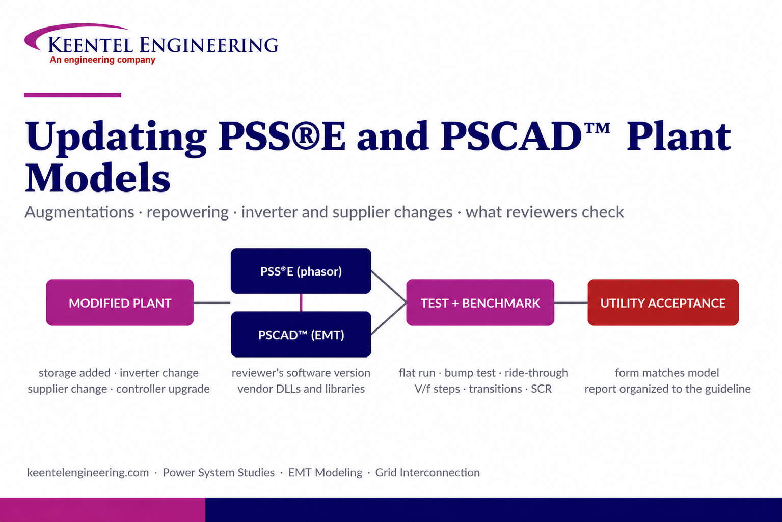
By SANDIP R PATEL
•
September 22, 2026
Learn how PSS®E and PSCAD™ model updates support plant augmentations, repowering, equipment changes, testing, benchmarking, and grid compliance.





