A Coordinated Electric System Interconnection Review—the utility’s deep-dive on technical and cost impacts of your project.
Challenge: Frequent false tripping using conventional electromechanical relays
Solution: SEL-487E integration with multi-terminal differential protection and dynamic inrush restraint
Result: 90% reduction in false trips, saving over $250,000 in downtime
| Category | Metric |
|---|---|
| VPP capacity (Lunar Energy) | 650 MW |
| Lunar funding raised | US$232 million |
| Data center BESS example | 31 MW / 62 MWh |
| ERCOT grid-scale batteries | 15+ GW |
| LDES tenders (H1 2026) | Up to 9.3 GW |
| Lithium-ion share of LDES by 2030 | 77% |
| FEOC initial threshold | 55% |
| BESS tariff rate (2026) | ~55% |
| Capacity gain from analytics | 5–15% |
What is T&D Co-Simulation?
Confusing Physical Connections with Logical Nodes in IEC 61850
Switching in Transmission and Distribution Systems
Jun 11, 2026 | blog
Why switching matters
A power system exists to move generated energy from the point of production to the point of use safely, continuously, and at the right voltage. Generators convert mechanical energy into electrical energy, conductors carry the current, and transformers step the voltage up for efficient transmission and back down for distribution. Modern society's dependence on that chain is now so complete that an unplanned interruption is treated as a serious event rather than an inconvenience.
Switching is the deliberate act of changing the connection state of the network — opening or closing a circuit to add or remove an element. It is one of the most routine activities in any substation, and yet it is never trivial. Every switching operation reconfigures the topology of the network and disturbs the steady flow of energy. Whenever a steady state is interrupted, the system passes through a transient: a short-lived but often severe excursion of voltage and current that can exceed normal operating values by a wide margin. The discipline of switching is, at its core, the discipline of managing those transients so that the operation does its job without damaging equipment or destabilizing the grid.
This article walks through the four fundamental reasons a system is switched and the engineering duties each one imposes on the switching device.
The four reasons a network is switched
At a high level, switching serves four purposes:
Connecting or disconnecting system sections, loads, or consumers.
This is the everyday work of the system: energizing and de-energizing overhead lines, cables, transformers, capacitor banks, and reactors, or bringing individual loads in and out of service. In industrial plants this is by far the most frequent class of switching.
Transferring power flow from one circuit to another.
When current must keep flowing but needs to be rerouted — for example, moving load from one busbar to a parallel busbar — switching achieves the transfer without an interruption to the consumer.
Isolating components for maintenance or replacement.
Before a crew can safely work on a transformer, breaker, or line section, that equipment has to be separated from every energized source and connected to earth.
Isolating faulted sections.
Faults are inevitable. The job of protection and switching together is to detect a fault and remove the affected section fast enough to prevent equipment damage and avoid cascading instability. The classic case is the interruption of a short-circuit current.
These four reasons map onto four distinct switching duties, each with its own physics and its own demands on the device.
Duty 1: Isolation and earthing
Isolation is the simplest switching operation in principle — it is normally a no-load operation — but it carries the highest personnel-safety stakes. Before anyone approaches equipment, that equipment must be visibly and reliably separated from every live part of the system and then bonded to earth.
The device that provides this separation is the disconnector (also called a disconnecting switch or isolator). Its defining requirement is a large, well-defined open gap that drives the probability of dielectric breakdown across the open contacts as close to zero as practical. In many jurisdictions, a visible break between the energized network and the work zone is a legal requirement, which is why outdoor air-insulated disconnectors are designed so the open position can be confirmed by eye. In gas-insulated switchgear (GIS), the conductors and switching elements sit inside metal enclosures filled with pressurized insulating gas, so the "visible" break is provided instead by certified position indication.
A subtlety that catches the inexperienced: even a no-load disconnector operation is not entirely current-free. Stray and bus capacitance means a small charging current always flows in an energized system, so opening a disconnector still draws and extinguishes a small arc. Disconnectors are not rated to interrupt meaningful current, which is exactly why switching sequences are interlocked so a disconnector is never asked to break load.
Earthing is the complementary operation: it connects a previously live part to ground. Under normal conditions, the section is de-energized first and the earthing switch simply establishes the safety bond. The demanding case is fault-make earthing — closing an earthing switch onto a section that may still be energized, or onto a point that can carry fault current depending on how the system neutral is grounded. Standard earthing switches must at minimum be able to carry the rated short-time fault current. Fast-acting and high-speed (fault-making) earthing switches go further: they are built to close into a fault, surviving the electromagnetic forces and arc energy of a make-onto-fault event.
Duty 2: Busbar-transfer switching
Reliability is engineered into substations through redundancy, and the most common form of that redundancy is a double-busbar arrangement. Busbar-transfer switching is the operation of moving load from one busbar to its parallel counterpart while the current keeps flowing — a commutation rather than an interruption.
Because both busbars are energized and effectively in parallel during the transfer, the disconnectors involved are not asked to interrupt the load. Instead, current commutates from one path to the other through the small loop voltage between the two busbars. The net load to the feeder continues uninterrupted, which is the whole point: customers see nothing. This is what allows a substation to be partially reconfigured — for maintenance on one bus, for example — without dropping load, provided the transfer is sequenced correctly and the parallel path can carry the current.
Duty 3: Load switching
Loads are switched constantly. In industrial environments, contactors handle the high-frequency switching of motors, pumps, furnaces, and similar equipment, often cycling many times per shift. In utility systems, load-break switches and circuit switchers are designed to interrupt normal load current — but deliberately not the full prospective fault current. That division of labor keeps the simpler, cheaper devices on routine duty while reserving fault interruption for circuit breakers.
The frequency of ordinary load switching in a utility is usually low. The important exception is reactive-power equipment — shunt capacitor banks and shunt reactors — which may be switched twice a day or more to manage voltage and reactive flow. And here the physics turns sharp.
Ordinary loads operate near unity power factor, so the current the device interrupts is close to a natural current zero when the voltage is also near zero — a comparatively gentle interruption. Shunt reactors and capacitor banks are different: their current leads or lags the voltage by nearly 90 electrical degrees. That phase relationship has severe consequences for the switching device:
- Capacitive switching stresses the device with a high recovery voltage. After current zero, the capacitor bank is left charged near peak voltage while the source swings to the opposite peak, so the open gap can see close to twice the peak phase voltage within half a cycle. If the gap re-conducts (a restrike), it can drive damaging voltage and current escalation.
- Inductive (reactor) switching carries the risk of current chopping — the device forcing current to zero before its natural zero — which converts the energy stored in the reactor's magnetic field into a transient overvoltage.
The underlying point is that reactors store energy in their magnetic field and capacitors store charge in their electric field. When a de-energization fails to extinguish cleanly, that stored energy is released back into the system and can damage the switchgear and adjacent equipment. This is why capacitor and reactor switching is treated as a specialized duty, frequently handled with controlled point-on-wave switching, definite-purpose breakers, or pre-insertion resistors
Duty 4: Fault-current interruption
The most demanding duty is clearing a short circuit, and it is worth following the sequence in detail because the timing is what protection engineers ultimately design around.
When a fault occurs, the resulting short-circuit current is sensed by protective relays. The relays continuously monitor current and voltage through instrument transformers — current transformers and voltage transformers — and compare those measurements against their settings. The interval between fault inception and the relay's decision to act, the relay time, is typically on the order of one to three half-cycles of the power frequency (50 or 60 Hz).
Once the relay decides, it energizes the trip coil of the circuit breaker. The trip command sets the operating mechanism in motion, and through its kinematic chain the breaker contacts begin to separate. After the opening time has elapsed, the arcing contacts part in all three poles — the instant known as contact parting or contact separation.
A few definitions anchor the rest of the process. A pole is the part of a switching device located in one phase of the network; a three-phase device therefore has three poles. A device with a single pole is single-pole; with more than one, it is multi-pole, and the poles are coupled to operate together. Within each pole, the interrupter (or interruption chamber) is where the current is actually broken — it houses the contact system, the arc-extinction mechanism, and the internal insulation. At higher rated voltages, a single pole may contain two or more interrupters in series so that the recovery voltage is shared; grading capacitors across each interrupter equalize that voltage distribution. Architecturally, a breaker may be built as three independent single-pole devices each with its own operating mechanism, or as one three-pole device sharing a single mechanism — and at the very highest voltages, even multiple mechanisms per pole.
The arc itself is central.
When the contacts separate, an electric arc forms in each pole's interrupter — the switching arc. Current cannot simply be forced to stop; interruption has to wait for a natural current zero. Because the arc behaves essentially as a resistance, the arc voltage and the current reach zero at the same instant. Right around current zero the energy fed into the arc channel is very low — at the zero itself there is none — and if the breaker's extinction medium is cooling the channel adequately at that moment, the current is interrupted and the gap recovers as an insulator.
There is a catch. A breaker is not necessarily ready to interrupt at the first current zero after the contacts part. It needs a minimum arcing time first — enough time to build sufficient cooling pressure in the extinction medium and/or to open the contacts far enough to withstand the recovery voltage. Only after that minimum arcing time has elapsed will the current be cleared at the next available current zero, and each phase clears at its own current zero. When the last pole interrupts, the fault is cleared.
The total elapsed time from energizing the trip coil to current interruption in all phases is the break time. Under IEEE C37.04, the rated interrupting time — measured from energization of the trip circuit to interruption in all phases — is expressed in power-frequency cycles. A "three-cycle breaker," then, is one that clears a fault within three power-frequency cycles. That single number quietly drives a great deal of system design: fault-withstand ratings of equipment,
protection coordination margins, and ultimately transient stability limits all depend on how fast the breaker can clear.
The thread running through all four duties
Across isolation, transfer, load switching, and fault clearing, the same principle recurs: every switching operation provokes a transient, and the engineering challenge is to size, select, and sequence devices so the transient stays within what the system can tolerate. A disconnector must never be asked to break load. A capacitor bank breaker must survive a recovery voltage that an ordinary load breaker would never see. A fault-clearing breaker must reach its dielectric strength faster than the transient recovery voltage rises across its gap. Get the match right and switching is invisible; get it wrong and the transient — not the steady state — is what fails the equipment.
For utilities and
industrial operators, the practical takeaway is that switchgear selection and switching procedures are not interchangeable commodities. They are duty-specific engineering decisions, and the cost of treating them otherwise shows up as restrikes, prestrikes, chopped-current overvoltages, and shortened equipment life.
Case Study 1: Eliminating Restrikes on a Frequently Switched Capacitor Bank
Background
An industrial facility operated a medium-voltage shunt capacitor bank that was switched on and off twice daily to manage power factor and voltage during shifting production loads. Over time, maintenance crews began finding evidence of dielectric distress on the switching device and elevated surge-arrester operations on the bank.
Challenge
The bank's breaker was a general-purpose device that had been specified primarily on its continuous current and fault rating, with little attention to capacitive switching duty. Because capacitive current leads the voltage by nearly 90 degrees, the recovery voltage across the open contacts climbed to roughly twice peak phase voltage within a half-cycle of interruption. The gap was occasionally re-conducting — a restrike — driving repetitive overvoltage transients into the bank and the adjacent bus each time the bank was de-energized. The high switching frequency turned an occasional stress into a daily one.
Approach
Engineers reviewed the actual switching duty rather than the nameplate ratings, characterized the recovery-voltage profile, and confirmed restrike behavior through transient monitoring during scheduled operations. The general-purpose breaker was replaced with a definite-purpose, restrike-free capacitor-switching device, and controlled point-on-wave switching was added so that closing occurred near voltage zero and opening was coordinated to the most favorable current zero. Surge arresters were re-coordinated to the corrected transient envelope.
Outcome
Restrike events were eliminated, and the daily overvoltage transients disappeared from the monitoring records. Surge-arrester duty fell back within design margins, and the expected service life of the bank and switchgear was restored. The broader lesson — that switching duty, not just steady-state ratings, must drive device selection — was carried into the facility's switchgear specification standard.
Case Study 2: Reconfiguring a Double-Busbar Substation Without Dropping Load
Background
A transmission substation serving a cluster of critical industrial and commercial customers needed a major refurbishment of one of its two busbars, including replacement of aging disconnectors and support structures. The customers could not tolerate a planned outage, and the utility's reliability commitments left no room for an unplanned one.
Challenge
All feeders on the busbar scheduled for work had to be moved to the parallel busbar while remaining energized, and the transfer had to be executed without any interruption to load. The risk was that an incorrectly sequenced operation could ask a disconnector to break load current — an operation it is not rated for — or could momentarily parallel the buses in a way that exceeded equipment limits.
Approach
The team developed a busbar-transfer sequence built on the double-busbar redundancy already present in the design. With both buses energized and briefly in parallel, the load current was commutated feeder by feeder onto the healthy busbar through the small inter-bus loop voltage, so no disconnector was ever asked to interrupt current. Interlocking was verified end to end before the work began, and each transfer step was confirmed by position indication before proceeding. Once all feeders had transferred, the busbar under refurbishment was isolated and earthed for safe access.
Outcome
The full feeder set was transferred to the parallel busbar with no interruption to any customer, and the refurbishment proceeded on a fully isolated, earthed busbar. The operation confirmed the value of designed-in redundancy and disciplined interlocking: a substantial maintenance program was completed with zero customer minutes lost and no exposure of switching devices to duties beyond their rating.
Case Study 3: Faster Fault Clearing to Restore Transient Stability Margin
Background
A utility operating a heavily loaded transmission corridor found that stability studies for a planned generation addition no longer closed with comfortable margin. The corridor's existing breakers were older, slower-clearing units, and the cumulative fault-clearing time was eroding the system's ability to ride through a nearby three-phase fault.
Challenge
Transient stability depends strongly on how quickly a fault is removed. The existing breakers, combined with the relay times of the legacy protection, produced a total break time long enough that, under the new dispatch, the corridor's machines risked losing synchronism for a close-in fault. Simply adding generation without addressing clearing time would have reduced the operable transfer limit on the corridor.
Approach
Engineers broke the clearing sequence into its components — relay time, opening time, and arcing time — and targeted each. Legacy electromechanical protection was upgraded to modern relays to shorten the detection interval, and the slower breakers were replaced with faster-clearing units rated at a lower cycle count, reducing the break time from trip-coil energization to interruption in all phases. Where pole construction allowed, independent-pole operation was retained to support single-phase tripping schemes. The improvements were validated against the same stability cases that had originally failed.
Outcome
Total fault-clearing time was reduced enough to restore stability margin under the new generation profile, and the corridor's transfer limit was preserved rather than de-rated. The project illustrated how the single number that characterizes a breaker's interrupting time — expressed in power-frequency cycles — propagates all the way up to system-level stability, and why protection and switchgear upgrades are often most valuable when planned together
Frequently Asked Questions
1. What does "switching" actually mean in a power system?
Switching is any deliberate change to the connection state of the network — opening or closing a circuit to bring an element in or out of service, reroute power, isolate equipment, or clear a fault. Because it changes the network topology and disturbs the steady flow of energy, every switching event produces a transient that the system must absorb.
2. Why are transients such a concern during switching?
A transient is a short-lived disturbance in voltage and current that appears whenever a steady-state condition changes. These excursions frequently exceed normal operating values, so they can over-stress insulation and switchgear even though they last only milliseconds. Managing transients is the central design problem in switching.
3. What is the difference between a disconnector and a circuit breaker?
A disconnector (isolator) provides a visible, reliable open gap for safety and is normally operated only at no load — it is not rated to break significant current. A circuit breaker is built to interrupt current, including full fault current, under controlled arc-extinction conditions. Confusing the two is dangerous: a disconnector opened under load can sustain an uncontrolled arc.
4. If a disconnector is "no-load," why does it still arc?
Because stray and bus capacitance means a small charging current always flows in an energized system. Opening the gap interrupts that tiny current, which produces a small arc that must extinguish. It is minor compared with load or fault interruption, but it is the reason disconnectors still have a defined switching capability for capacitive currents.
5. What is the role of an earthing switch?
An earthing switch bonds a previously live section to ground so crews can work safely. Under normal conditions the section is de-energized first. Earthing switches must at least carry the rated short-time fault current, and fault-making (high-speed) earthing switches are additionally rated to close directly onto an energized or fault-carrying section.
6. Why do some standards require a "visible break"?
A visible open gap lets personnel confirm by direct observation that equipment is isolated before approaching it, which is a strong safeguard against switching errors. In GIS, where the gap is inside a sealed enclosure, certified position indication serves the same assurance function.
7. What is busbar-transfer switching and why is it useful?
It is the operation of moving load from one busbar to a parallel busbar without interrupting the current. Because both busbars are energized in parallel during the transfer, the current commutates smoothly and customers see no interruption. This allows part of a substation to be reconfigured — for maintenance, for example — while keeping load supplied.
8. Why are shunt capacitors and reactors switched so much more often than normal loads?
They are reactive-power resources used to regulate voltage and reactive flow, which changes throughout the day. As a result they may be switched twice daily or more, whereas ordinary load switching in a utility is comparatively infrequent.
9. Why is switching reactive equipment more difficult than switching ordinary load?
Normal loads operate near unity power factor, so current and voltage zeros nearly coincide and interruption is gentle. Capacitive and inductive currents are roughly 90 degrees out of phase with the voltage, which produces high recovery voltages (capacitor switching) or current-chopping overvoltages (reactor switching). Both can stress or damage equipment if not handled with appropriate devices.
10. What happens if a capacitor or reactor de-energization fails to clear cleanly?
Reactors store energy in their magnetic field and capacitors store charge in their electric field. A failed interruption releases that stored energy back into the system as a transient, which can damage the switchgear and nearby components. This is why these duties often use controlled (point-on-wave) switching or definite-purpose breakers.
11. What is the sequence of events when a circuit breaker clears a fault?
A fault current is detected by protective relays (relay time, typically one to three half-cycles), the relay energizes the trip coil, the operating mechanism drives the contacts apart (opening time), an arc forms and burns until a suitable current zero (arcing time), and the current is interrupted in each phase. When the last pole clears, the fault is cleared.
12. What is "relay time"?
It is the interval between the inception of a fault and the moment the protection system issues a trip command. It is generally on the order of one to three half-cycles of the power frequency. It does not include the breaker's own opening and arcing time.
13. What is the difference between opening time, arcing time, and break time?
Opening time runs from trip-coil energization to contact separation. Arcing time runs from contact separation to current interruption. Break time is the total from trip-coil energization to interruption in all three phases — effectively opening time plus arcing time.
14. Why can't a breaker interrupt current the instant the contacts open?
Current can only be interrupted at a natural current zero, and even then the breaker needs a minimum arcing time first to build adequate cooling pressure in its extinction medium and to open the gap far enough to withstand the recovery voltage. Only after that minimum arcing time can it clear at the next current zero.
15. What is a "pole" and what is an "interrupter"?
A pole is the part of a switching device in one phase; a three-phase breaker has three poles. The interrupter (interruption chamber) is the part of the pole where the current is actually broken — it contains the contacts, the arc-extinction mechanism, and the insulation. High-voltage poles may have several interrupters in series.
16. Why are multiple interrupters placed in series in a single pole, and what do grading capacitors do?
At high rated voltages, one interrupter cannot withstand the full recovery voltage, so two or more are placed in series to share it. Grading capacitors across each interrupter ensure the voltage divides evenly; without them, an uneven split could overstress one interrupter and cause it to fail.
17. What does a "three-cycle breaker" mean?
Under IEEE C37.04, the rated interrupting time is expressed in power-frequency cycles. A three-cycle breaker clears a fault within three power-frequency cycles measured from trip-circuit energization to interruption in all phases. Faster breakers improve fault-withstand margins and transient stability.
18. Why does the switching arc behave like a resistor, and why does that matter?
Near current zero the arc is essentially resistive, so the arc voltage and current reach zero at the same instant. Because energy input is minimal at that moment, an adequately cooled gap can recover its insulating strength and interrupt the current. This resistive behavior at current zero is the physical basis of AC current interruption.
19. How does a single circuit breaker's design vary between three single-pole units and one three-pole unit?
A breaker can be built as three independent single-pole devices, each with its own operating mechanism, or as one three-pole device with a shared mechanism. Single-pole construction enables independent-pole operation (useful for single-phase tripping and reclosing); at the highest voltages, a pole may even use multiple mechanisms. The choice affects control schemes, cost, and protection philosophy.
20. What is the practical takeaway for selecting switchgear?
Switching duty is specific, not generic. A device suited to routine load switching is not necessarily suited to capacitor, reactor, or fault duty, and isolation devices must never be operated under load. Matching the device and the switching procedure to the actual duty prevents restrikes, chopped-current overvoltages, and premature equipment failure.

About the Author:
Sonny Patel P.E. EC
IEEE Senior Member
In 1995, Sandip (Sonny) R. Patel earned his Electrical Engineering degree from the University of Illinois, specializing in Electrical Engineering . But degrees don’t build legacies—action does. For three decades, he’s been shaping the future of engineering, not just as a licensed Professional Engineer across multiple states (Florida, California, New York, West Virginia, and Minnesota), but as a doer. A builder. A leader. Not just an engineer. A Licensed Electrical Contractor in Florida with an Unlimited EC license. Not just an executive. The founder and CEO of KEENTEL LLC—where expertise meets execution. Three decades. Multiple states. Endless impact.
Services

Let's Discuss Your Project
Let's book a call to discuss your electrical engineering project that we can help you with.
About the Author:
Sonny Patel P.E. EC
IEEE Senior Member
In 1995, Sandip (Sonny) R. Patel earned his Electrical Engineering degree from the University of Illinois, specializing in Electrical Engineering . But degrees don’t build legacies—action does. For three decades, he’s been shaping the future of engineering, not just as a licensed Professional Engineer across multiple states (Florida, California, New York, West Virginia, and Minnesota), but as a doer. A builder. A leader. Not just an engineer. A Licensed Electrical Contractor in Florida with an Unlimited EC license. Not just an executive. The founder and CEO of KEENTEL LLC—where expertise meets execution. Three decades. Multiple states. Endless impact.
Leave a Comment
Thank you for contacting us.
We will get back to you as soon as possible.
We will get back to you as soon as possible.
Oops, there was an error sending your message.
Please try again later.
Please try again later.
Related Posts
By SANDIP R PATEL
•
July 27, 2026
Learn how gas-insulated substations (GIS) improve safety, reliability, and space efficiency with 138 kV design, protection, insulation coordination, and real-world case studies.
By SANDIP R PATEL
•
July 25, 2026
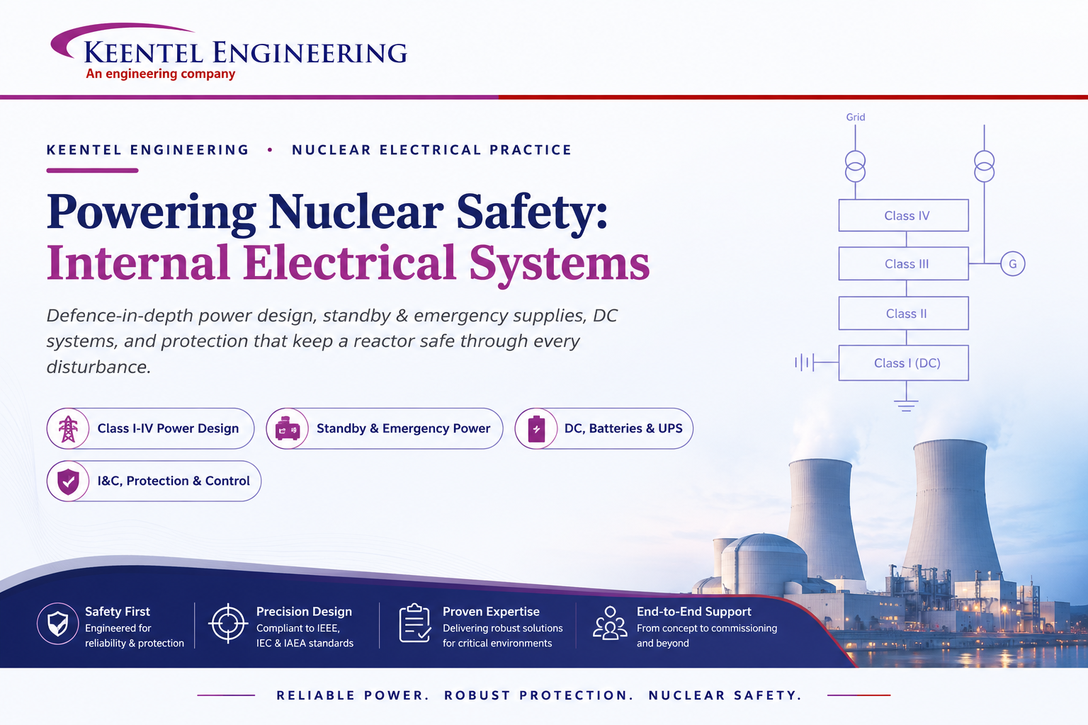
Learn how Class I–IV electrical systems, defence-in-depth, standby and emergency power, DC systems, protection, and load transfer ensure nuclear power plant safety.
By SANDIP R PATEL
•
July 24, 2026
Learn GIS substation safety best practices, SOPs, commissioning, maintenance, interlocking, earthing, and testing to improve grid reliability and uptime.
By SANDIP R PATEL
•
July 23, 2026
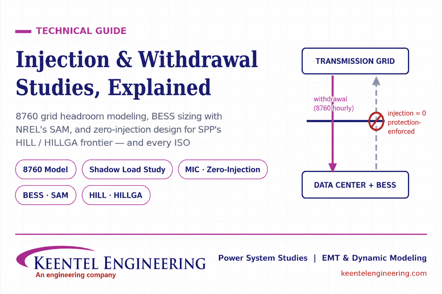
Learn how injection and withdrawal studies, 8760 headroom modeling, zero-injection engineering, and SPP HILLGA improve large load grid interconnections
By SANDIP R PATEL
•
July 21, 2026
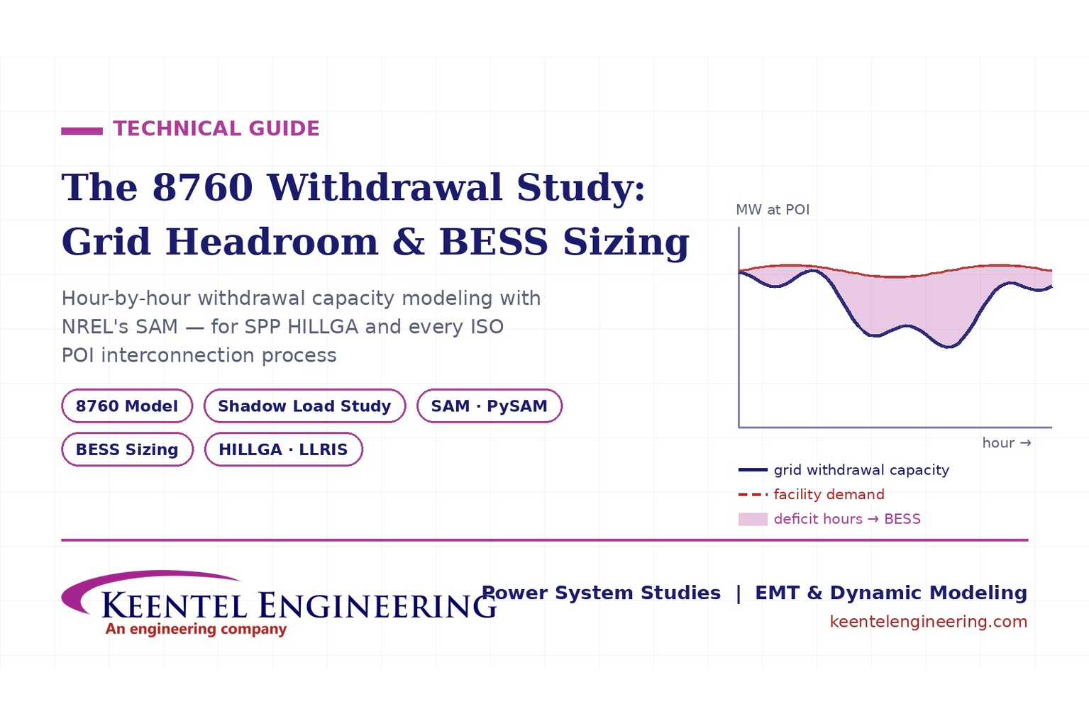
Learn how an 8760 withdrawal study models hourly grid headroom and uses SAM-based BESS sizing for large-load interconnection projects.
By SANDIP R PATEL
•
July 21, 2026
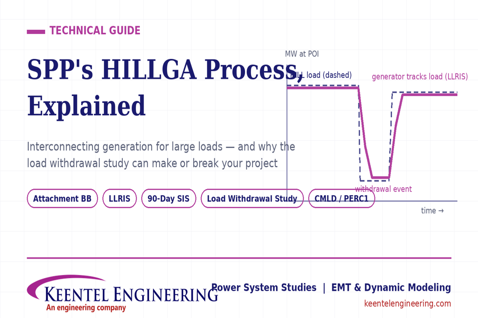
Learn how the SPP HILLGA process supports data center generation interconnection and why an 8760 withdrawal study can determine project success.
By SANDIP R PATEL
•
July 19, 2026
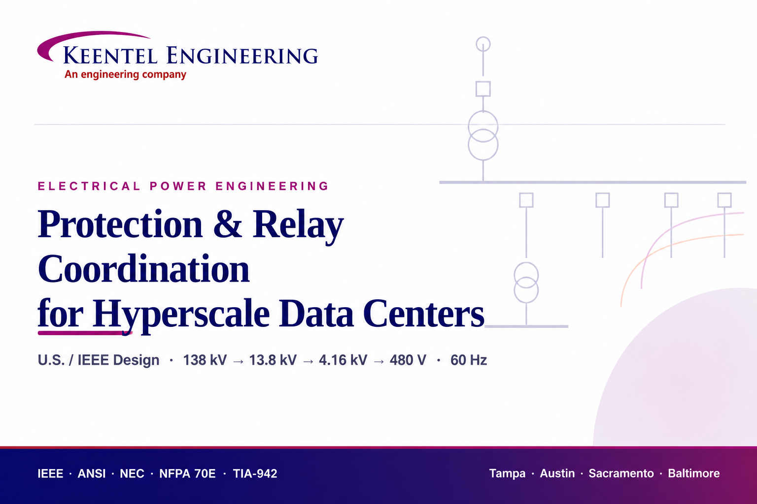
Learn electrical protection and relay coordination for hyperscale data centers with IEEE standards, short-circuit studies, arc-flash analysis, and MV protection.
By SANDIP R PATEL
•
July 18, 2026
Explore Battery Energy Storage System components, including cells, PCS, BMS, EMS, cooling, fire protection, sizing, safety, and grid codes.

By SANDIP R PATEL
•
July 18, 2026
Explore how grid-forming inverters support BESS, synthetic inertia, grid-code compliance, plant sizing, testing, and project revenue.