
A Coordinated Electric System Interconnection Review—the utility’s deep-dive on technical and cost impacts of your project.
Challenge: Frequent false tripping using conventional electromechanical relays
Solution: SEL-487E integration with multi-terminal differential protection and dynamic inrush restraint
Result: 90% reduction in false trips, saving over $250,000 in downtime
ERCOT enforces all of the above through simulation, which means your model is your compliance case. The bar is now high:
- Whole-facility scope. The model must represent everything the IT load, the UPS and power conversion, the cooling plant, the protection and control systems in formats compatible with ERCOT's study platforms (PSS/E, PSCAD, TSAT).
- Real control loops, not approximations. Generic textbook representations are unacceptable. The model must capture the actual inner control behavior of your power electronics.
- Hardware-validated converter models. For electronic loads, the PSCAD model must be benchmarked against actual hardware testing including voltage ride-through and subsynchronous response. A model assembled from standard PSCAD library blocks fails by definition, because a generic block has never been tested against your vendor's hardware. The good news: validation is a hardware-type test, so results for a given converter product are reusable across every facility that uses it.
- Format migration. Facilities that previously submitted the older composite load model (CMLD) format must transition to EPRI's PERC1 format.
- Three checkpoints. Models are reviewed before the stability study begins (no model, no study), before each quarterly stability assessment, and for electronic loads one final time before energization, when you must submit as-built models with a documented comparison against the previously studied data and a sworn attestation that the model matches actual field settings. ERCOT's review takes 10 business days, extendable by 20 put it on your critical path.
- A living obligation. Change your technology, controls, or relay settings in a way that affects ride-through including converting a crypto mining site to an AI data center — and you've triggered a new interconnection study, even if your megawatts don't change.
| Parameter | Detail |
|---|---|
| System | 230 kV / 138 kV transmission corridors, wind and wet-snow icing exposure |
| Data basis | 15 years of minute-resolution forced-outage records + regional weather observations |
| Core methods | Event grouping, MVA performance curves, time-to-95%-restore, area outage rate curves, fragility modeling, rerun-history benefits, exceedance and log-domain risk metrics |
| Headline result | ≈85% of maximum resilience benefit at 60% of original capital; worst-event restoration window cut from 11 days to 5 in rerun-history terms |
| Decision supported | Capital portfolio selection; resilience plan filing; post-investment verification framework |
| System / Topic | Governing Standard(s) | What It Controls |
|---|---|---|
| Overall plant electrical distribution | IEEE 141 (Red Book); IEEE 666 | Distribution architecture, voltage selection, design of generating station auxiliary service systems |
| Power system studies | IEEE 399 (Brown Book); IEEE 551 | Load flow, symmetrical/asymmetrical short circuit, motor starting methodologies down to the lowest LV panelboard |
| Protection & coordination | IEEE 242 (Buff Book); IEEE 3004.5; IEEE C37 series | Generator relaying (21, 59N, 87G), time-current coordination, selective clearing between LV and MV tiers |
| GSU / UAT / SST transformers | IEEE C57.12.00 and C57 family | Transformer ratings, impedance, testing, loading |
| HV switchyard breakers | IEEE C37.06 | AC high-voltage circuit breaker preferred ratings |
| MV switchgear (13.8 kV) | IEEE C37.20.2; IEEE C37.20.7 | Metal-clad construction, compartmentalization, vacuum breakers; arc-resistant design with plenum venting |
| MV cable | UL 1072; ICEA S-93-639 (NEMA WC 74) | Type MV-105 shielded cable, 133% insulation level for HRG systems |
| LV switchgear (480 V) | IEEE C37.13; UL 1558 | Metal-enclosed LV power circuit breaker switchgear to 635 V, draw-out ACBs with electronic trip units |
| Motor control centers | UL 845; NEMA ICS 18 | LV-MCC construction, MCCB/MCP protection for motors under ~200 HP |
| Motors | NEMA MG-1 | Motor performance, starting characteristics, service factors |
| DC & battery systems | IEEE 485; IEEE 946 | Lead-acid battery sizing (125/250 VDC), DC auxiliary system design |
| Grounding | IEEE 80; IEEE 142 (Green Book) | Ground grid step/touch potential limits; system grounding including high-resistance grounding |
| Lightning protection | IEEE 998 | Direct-stroke shielding of switchyard and outdoor generator structures |
| Arc flash & electrical safety | IEEE 1584; NFPA 70E | Incident energy calculation; worker safety boundaries and PPE |
| Fire protection | NFPA 850 | Fire protection and risk management for combustion turbine generating plants |
| Installation code | NEC (NFPA 70); NESC | Wiring methods inside the plant fence; overhead/outdoor clearances at the switchyard |
| Interconnection & compliance | FERC LGIP; NERC MOD-025/026/027, PRC-019/024/029, FAC-008 | Interconnection process, model validation, protection/ride-through coordination, facility ratings |
| IFC / Construction Deliverable | Purpose |
|---|---|
| Stamped IFC packages | Legal basis for construction; P.E. responsible charge |
| Final relay settings & TCCs | Protection as-installed matches the coordination study |
| Calculation archive | Owner records; NERC audit evidence trail |
| Commissioning procedures | Safe, sequenced energization; MOD field testing |
| Construction support | RFIs, field changes, FAT/SAT witness |
| As-builts & model handoff | Operating baseline; future study currency |
| Metric | Outcome |
|---|---|
| Defects found pre-occupancy | Three topology defects and one settings-mismatch family corrected before load migration; the shared-switchboard defect alone would have invalidated the concurrently-maintainable claim on day one |
| IST findings | Fourteen additional discrepancies surfaced under scenario testing (control logic, alarm mapping, one generator sequencing fault) — all closed before handover instead of during operations |
| Black-building test | Passed on second execution; the first attempt exposed the generator sequencing fault under true block load, exactly the failure the compressed plan would never have found |
| Handover quality | Operations team certified on the actual failure scenarios; corrected EOPs and settings documentation delivered as controlled documents |
| Business outcome | Occupancy proceeded three weeks behind the original date — against an independent estimate that the uncorrected sequencing fault carried a high probability of a full facility outage within the first year |
Part 2 — Frequently Asked Questions: Large Load Interconnection
An electric grid must remain in continuous balance — generation onto the grid must equal consumption from it at every instant. PJM achieves this balance, and prices it, through a layered market architecture. Each layer operates on a different time horizon, and each one touches project economics differently.
Grid-Forming Inverters
From Niche BESS Application to Standard Grid Requirement

Jul 18, 2026 | Blog
1. Introduction: A Paradigm Shift in How Grids Are Held Together
For roughly a century, the frequency and voltage of every large power system on Earth were created by spinning metal. Coal, gas, nuclear, and hydro plants did more than deliver energy — the rotating mass of their turbine-generator shafts physically established the 50 Hz or 60 Hz heartbeat of the grid and resisted every disturbance with stored kinetic energy. Inverter-based resources (IBRs) such as solar, wind, and battery energy storage systems (BESS) upended that arrangement. Historically, these resources have been grid-following: fast, precise, and responsive — but fundamentally dependent on an externally established voltage waveform to synchronize to.
Grid-forming (GFM) inverter technology closes that gap. A grid-forming inverter does not wait for the grid to tell it what to do; it establishes voltage magnitude, angle, and frequency itself, behaving toward the network the way a synchronous machine does. In doing so, it provides the services a high-renewables grid cannot live without: synthetic inertia, fast fault current, phase-angle jump withstand, voltage stiffness, oscillation damping, and even black-start capability.
What was, only a few years ago, a niche capability proven mainly on island grids has become a mainstream requirement. Transmission system operators (TSOs) across Europe, Australia, parts of Asia-Pacific, Latin America, and a growing number of North American markets have moved from technical white papers to binding grid-code mandates and, in some cases, to dedicated revenue mechanisms that pay batteries for inertia. This article reviews the technology, the physics of inertia, the global regulatory landscape, the emerging revenue models, and — most importantly for asset owners and developers — the plant-level engineering that determines whether a grid-forming project actually works and actually gets paid.
2. Grid-Following vs. Grid-Forming: The Fundamental Difference
The most widely used shorthand in the industry is that a grid-following (GFL) inverter behaves like a controlled current source, while a grid-forming inverter behaves like a voltage source behind an impedance. That single sentence carries almost everything that matters.
2.1 The Grid-Follower: Fast, but Always One Step Behind
A grid-following inverter continuously measures the grid voltage — typically through a phase-locked loop (PLL) — and injects current aligned to that measured waveform to hold its commanded active and reactive power setpoints. When the grid frequency sags after a generation trip, the GFL inverter does exactly what it was designed to do: it tracks the moving waveform and holds its megawatt output constant. Every corrective action (frequency response, voltage support, oscillation damping) requires a measurement, a control decision, and a dispatch — and that measurement-control-dispatch cycle introduces dead time. A useful mental model is that a grid-following inverter is a grid copier: when the voltage steps, it steps with it; when the frequency accelerates, it accelerates with it; when the phase angle jumps, it snaps to the new angle. It faithfully reproduces whatever the grid does, including the disturbance itself.
2.2 The Grid-Former: Holding Its Ground and Letting Physics Work
A grid-forming inverter inverts that logic. During the transient and sub-transient window immediately after a disturbance, it holds its internal voltage — both magnitude and angle — steady. Because the plant now looks like a stiff voltage source connected to the disturbed network through an impedance, basic circuit physics does the rest: whatever current is needed to oppose the disturbance flows naturally and instantaneously, with no measurement latency and no dispatch delay. In that sense a grid-forming inverter is a grid corrector rather than a grid copier. Consider four canonical grid events:
- Voltage magnitude step. The grid-former sources or absorbs reactive current instantly to partially restore the voltage, exactly as a synchronous machine's field-driven EMF would.
- Rate of change of frequency (RoCoF). As frequency accelerates or decelerates, the grid-former initially maintains its own angle trajectory, exchanging active power with the grid just as a decelerating flywheel releases kinetic energy — this is synthetic inertia.
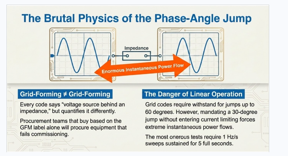
- Phase-angle jump. When the network voltage angle suddenly shifts (a common consequence of line switching or faults), a large angle difference appears across the coupling impedance and a substantial power flow results, kicking the grid back toward alignment. Grid codes commonly require withstand capability for angle jumps of up to 60 degrees.
- Voltage imbalance. Where a grid-follower typically regulates negative-sequence current to zero (preserving current headroom for its day job), a grid-former naturally provides bespoke per-phase current that counteracts the imbalance.
KEENTEL INSIGHT — Why Latency Is the Whole Story
The distinction is not that grid-forming responds faster than grid-following — modern GFL controls are extraordinarily fast. The distinction is that a grid-former's stabilizing response requires no control action at all in the first instants. The response is a property of the physics of a voltage source behind an impedance, not the output of a control loop. That is what makes it functionally equivalent to rotating inertia.
3. Inertia: What It Is, How It Is Measured, and Why It Is Vanishing
3.1 The Inertia Constant
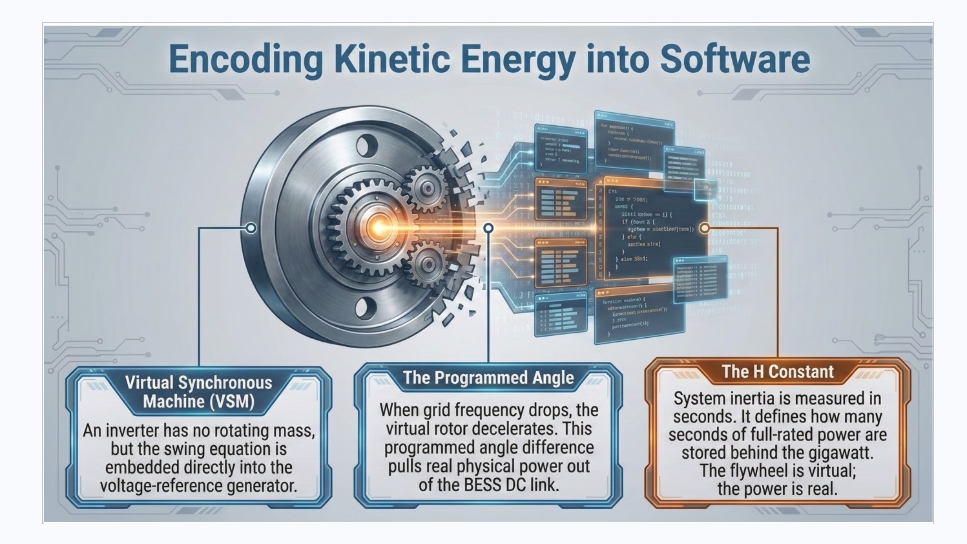
System inertia is quantified through the inertia constant H, expressed in seconds. Conceptually, take the kinetic energy stored in a machine's rotating mass — measured in gigawatt-seconds, the same energy unit as gigawatt-hours, only smaller — and divide it by the machine's rated active power in gigawatts. The result answers a simple question: how many seconds' worth of full-power energy is stored behind every gigawatt on the grid? The higher the aggregate H, the shallower the rate of change of frequency (RoCoF) after any generation-load imbalance, and the more time slower frequency-response resources have to act.
3.2 Not All Generators Are Equal
Different technologies bring dramatically different inertia contributions. Nuclear units, with their massive high-speed turbine shafts, sit at the top of the range. Combined-cycle and open-cycle gas plants contribute meaningfully but less. Biomass fleets average lower still, in part because many are internal-combustion engine plants with modest rotating mass. Wind and solar operating through conventional grid-following inverters contribute exactly zero — and, crucially, every megawatt-hour of GFL renewable output that displaces a synchronous machine removes that machine's inertia from the system in the same moment. Purpose-built solutions exist at the other extreme: synchronous condensers are, in effect, freely spinning flywheel machines built for nothing but inertia and fault current, and they deliver high inertia constants. Grid-forming BESS is unique in the lineup: because its 'flywheel' is a set of equations in software, its effective inertia constant is a design parameter — tunable across a wide range, subject to the hardware sizing consequences discussed in Section 7.
| Technology | Typical Inertia Contribution | Notes |
|---|---|---|
| Nuclear steam turbine | Highest of the conventional fleet | Very large rotating mass; high H constant |
| Gas / coal steam & CCGT | Moderate to high | Contribution disappears when units are decommitted |
| Biomass / biogas engines | Low to moderate (fleet average) | Reciprocating-engine plants dilute the average |
| Wind & solar (grid-following) | Zero | Displace synchronous inertia as penetration rises |
| Synchronous condenser | High (purpose-built) | Inertia and fault current only; dedicated capex |
| Grid-forming BESS | Software-defined; wide tunable range | H is a design choice with hardware sizing implications |
3.3 The Declining Floor
System planners do not design for average conditions; they design for the worst credible hours. A revealing metric is P10 system inertia — the level of inertia at or below which the grid operates during the worst ten percent of hours in a year. Across European systems, that floor has been trending steadily downward as synchronous plant retires or is displaced in the dispatch merit order. Low-inertia hours are exactly the hours when renewables output is highest, thermal units are decommitted, and the system is most exposed.
3.4 Why Planners Care: Cost and Catastrophe
There are two distinct drivers. The first is economic: on a low-inertia grid, frequency moves faster and farther after every imbalance, so more — and faster — frequency response must be procured to arrest it. Running a low-inertia grid is simply more expensive hour by hour. The second is security: interconnected continental systems can, under extreme stress, split into separate frequency islands along internal transmission bottlenecks. Such a system separation has happened before on the European interconnection, and the fault lines of a future split are broadly predictable. Notably, the planning need is asymmetric: regions prone to surplus generation after a split require negative inertia capability (resisting over-frequency), while import-dependent regions require positive inertia (resisting under-frequency). Grid-forming resources inherently provide both — a decelerating virtual flywheel absorbs energy just as readily as an accelerating one releases it.
KEENTEL INSIGHT — Inertia Is a Locational Product
Even where procurement frameworks accept inertia from anywhere in a control area, stability studies identify clear regional needs — and regions can even need over-frequency (negative) inertia rather than under-frequency support. Developers who understand the locational stability picture can anticipate where future locational price signals, or future bid rejections in saturated zones, are most likely to emerge.
4. How a Battery Emulates a Flywheel
An inverter has no rotating mass, but it can carry the equations of one. Virtual synchronous machine (VSM) and related grid-forming control structures embed the swing equation of a rotating machine in the inverter's voltage-reference generator. When grid frequency begins to fall, the virtual rotor 'decelerates' according to its programmed inertia constant, and the resulting angle difference between the inverter's internal voltage and the grid pulls real power out of the DC link and into the network — precisely the behavior of a flywheel giving up kinetic energy. The injected power in the first hundreds of milliseconds reduces the initial RoCoF, which produces two system-level benefits: primary frequency response resources gain time to act, and the frequency nadir they must arrest is shallower.
Because the inertia constant is a software parameter, a grid-forming BESS can present anywhere from a token H to values at or beyond the highest synchronous machines — some markets accept inertia bids up to 12.5 seconds. But software generosity must be backed by hardware honesty: the active power that a 12.5-second virtual flywheel must deliver during a severe RoCoF event is very real, and it must flow through real semiconductors, real batteries, real transformers, and real cables. That tension between what the controls promise and what the plant can physically deliver is the central engineering theme of grid-forming design, and we return to it in Section 7.
5. The Global Regulatory Landscape: Three Ways to Require Grid-Forming
Grid-forming requirements are proliferating worldwide, but they are far from uniform. Broadly, every framework we have reviewed falls into one of three archetypes — and a growing number of jurisdictions combine them.
5.1 Archetype 1: Blanket Mandate Within Inherent Limits
The simplest approach: every new BESS must operate in grid-forming mode whenever it has headroom or footroom within its rated capability envelope. No specific inertia constant, overcurrent margin, or droop characteristic is prescribed. Nordic system operators, the Texas market (with requirements phasing in during 2026), and a major Midwestern U.S. market (effective 2025) have all taken this route, and the pan-European transmission operators' framework points the same direction, with individual national codes to follow. The strength of this model is speed of deployment; its weakness is that, absent quantified requirements, developers rationally build the minimum. Most projects in mandate-only markets are configured with the lowest stable inertia setting — nobody adds hardware margin out of goodwill.
5.2 Archetype 2: Mandate Plus Explicit Overcurrent Capability
Some grids — often islanded, weakly interconnected, or topologically stressed — go further and require capability above 1.0 per unit current. One Pacific island utility has long required substantial overcurrent for up to five seconds. Chile's requirement, effective early this year, calls for significant overcurrent sustained for several seconds. A recent Iberian proposal specifies overcurrent for roughly half a second. Most demanding of all, one Latin American code requires plants to ride a 30-degree phase-angle jump without entering current limiting — that is, remaining in linear operation. Whether intended or not, that single sentence drives a very large short-duration overcurrent rating, because when two stiff voltage sources separated by a modest impedance suddenly develop a 30-degree angle difference, the resulting power flow is enormous.
5.3 Archetype 3: Market-Based Incentives — Carrots and Sticks
The third archetype attaches money to grid-forming behavior. Three national implementations illustrate the spectrum:
- Great Britain — stability tenders. The system operator first ran pathfinder-style stability tenders, in which grid-forming batteries offered inertia at the lowest cost of any technology — logically, since a battery earns its keep in energy and ancillary markets and sells inertia as an incremental service, whereas a synchronous condenser must recover its entire capital cost from stability payments alone. The transition from pathfinder contracts to an enduring tender framework has, however, been turbulent: in a recent tender round, every participating battery was excluded on technical eligibility grounds — including assets already delivering inertia under earlier contracts — while requirement documents evolved through multiple versions with limited transparency. The episode underlines that market design maturity matters as much as technology maturity.
- Australia — the avoidable charge. Rather than paying for grid-forming, the market charges for its absence: adding grid-following capacity at designated nodes triggers a locational system strength charge, avoidable by installing grid-forming capability. The result is one of the highest grid-forming BESS penetrations in the world, with announced projects suggesting the share will rise further. One caution: because the charge regime emphasizes fault-level contribution over inertia, many plants procure grid-forming inverters that are minimally tuned for inertial response — a reminder that grid-forming is not a single homogeneous product. Network companies in the region have also begun procuring system strength from grid-forming batteries directly, converting the stick into an emerging carrot.
- Germany — availability-based inertia contracts.
A newly opened procurement lets projects lock in inertia revenue on contracts of two to ten years, with prices administratively set (reviewed on a two-year cycle) and payment tied to annual availability. A premium product requires at least 90% availability — suited to grid-forming BESS, synchronous condensers, and must-run units — while a second tier provides an uplift for partially available resources so that every new project has some incentive to install grid-forming capability. Contracts can include a run-up period, letting projects under development secure pricing before commissioning. Operators have signaled leniency on location in the near term, accepting projects anywhere rather than only in study-identified need zones — a deliberate choice to avoid missing the current construction wave.
| Model | Mechanism | Representative MarketsRepresentative Markets | Key Risk / Caveat |
|---|---|---|---|
| Blanket mandate | GFM required within inherent limits; no quantities prescribed | Nordics; Texas (2026); U.S. Midwest (2025); pan-European direction | Minimum-compliance builds; little actual inertia added |
| Mandate + overcurrent | Explicit >1.0 p.u. current and/or linear angle-jump ride-through | Pacific islands; Chile; Iberian proposal | Hardware cost driven by a few seconds of capability |
| Market-based (carrot) | Tenders or availability-based multi-year contracts | Great Britain; Germany | Eligibility opacity; 90% availability cliff |
| Market-based (stick) | Locational charge on grid-following additions | Australia | Charge targets fault level; inertia tuning often minimal |
6. The Quantification Problem: Grid-Forming ≠ Grid-Forming
Every code says roughly the same words — 'voltage source behind an impedance' — and then quantifies the requirement completely differently. Four dimensions dominate, and each one lands directly on hardware sizing:
- Overload / overcurrent profile. Some markets mandate overcurrent magnitudes and durations outright (several seconds in the island and Chilean cases; sub-second in the Iberian proposal). Others — Great Britain and Germany — mandate nothing but allow voluntary short-term overload to be monetized as inertia or short-circuit-level revenue, with the permissible overload calculated from the design RoCoF and the bid inertia constant.
- Phase-angle jump. Withstand requirements commonly reach 60 degrees. Some codes additionally ask suppliers to declare the largest jump the plant can absorb before current limiting; at least one requires 30 degrees with no current limiting at all — a linear-operation requirement with outsized hardware consequences.
- RoCoF magnitude and duration. Design RoCoF values cluster around 1–2.5 Hz of total frequency excursion, but with very different intensities and durations. The most onerous published proof requirement asks plants to demonstrate inertial power delivery through 1 Hz/s sustained for five full seconds — a 5 Hz sweep spanning essentially the entire operational frequency band.
- Power oscillation damping (POD). Damping obligations range from very slow inter-area modes (fractions of a hertz, relevant in long, weakly meshed systems) up to 10–20 Hz control-interaction modes in other networks. A plant tuned for one duty is not automatically fit for the other.
KEENTEL INSIGHT — Read the Test, Not the Title
Two markets can both label a product 'grid-forming inertia' while one implies roughly 25–30% overload for five seconds and the other implies 100% overload for one second. Procurement teams that compare vendor offerings on the label rather than on the specific overload-duration-angle-RoCoF envelope routinely buy equipment that cannot pass the commissioning test. We recommend building a compliance matrix per target market before the PCS shortlist is drawn up — not after.
7. Plant Engineering: Where Grid-Forming Projects Are Won or Lost
7.1 The Whole Plant Forms the Grid — Not Just the Inverter
The grid-forming control lives in the power conversion system (PCS), and it is natural to start there. But the service is delivered by the plant. Providing an active-power surge for an angle jump or RoCoF event raises immediate questions across the entire one-line: Does the battery have the instantaneous power capability at the state of charge where the event finds it? What happens to cell balancing and state-of-charge estimation? Are protection settings, transformers, and cables secure under repeated short-duration overloads? And at the top of the stack, the power system plant controller (PPC) must adapt: a grid-following fleet does exactly what it is dispatched to do, but a grid-forming fleet has been granted autonomy, and the PPC's role shifts from commanding to supervising — keeping a continuous watchful eye on assets that are now allowed to act on their own.
7.2 Sizing for the Revenue You Want
Every plant's capability is bounded by its PQ envelope, and the binding corner is almost always discharge-overexcited. Real projects always carry some unintentional overbuild — inverter capacity installed above nominal plant rating, driven by reactive power obligations and design margin. Markets that monetize inertia let owners sell that margin. The economics get much better with deliberate short-term overload capability — a boost factor. With, say, 25% overload available for around five seconds, a plant can guarantee inertial power delivery without reserving any trading headroom: the battery trades its full nominal range while the overload band stands permanently ready for inertia. The energy involved is trivial (a few seconds); the power capability is everything.
The arithmetic compounds quickly at high inertia bids. Delivering the maximum biddable inertia constant of 12.5 seconds at a 2 Hz/s design RoCoF requires roughly 100% additional power above nominal — 200% total — for about one second. One second is nothing to a battery energetically and a long time to power electronics thermally. With legacy central-inverter topologies, reaching that capability means additional inverter blocks, additional footprint, additional transformers, and additional medium-voltage switchgear — costs that erode the very revenue being chased. Modern AC-block architectures with distributed string inverters and inherent overload headroom change that calculus, allowing meaningful oversizing within the existing footprint.
7.3 Degradation, Micro-Cycling, and the SOC Accuracy Trap
A common owner concern: if inertial response tracks every wiggle of grid frequency, will the battery micro-cycle itself to death? The evidence says no — with one important caveat. Analyses of historical frequency data, projected onto weakening grids, indicate that the energy throughput attributable to inertial response is small, and the oscillation frequencies involved fall outside the ranges that battery literature flags as accelerating lithium-ion degradation. Long-term wear is a manageable, minor line item.
The nearer-term issue is state-of-charge accuracy. Inertial duty means continuous low-magnitude, bidirectional current — precisely the regime where current transducers are least accurate. Small measurement errors around zero current integrate into meaningful SOC estimation drift, degrading dispatch accuracy and available-energy reporting well before any electrochemical degradation appears. Mitigations exist — periodic rebalancing routines, coulomb-counting correction strategies, and control filtering — but they must be engineered in deliberately. A related and underappreciated stress case: merchant strategies increasingly sweep the full SOC window, meaning plants spend hours near 0% SOC — exactly where a sudden full-plus-overload discharge kick from a grid event is hardest on cells and most likely to expose inadequate short-term peak discharge ratings. Cell and module suppliers should be told, contractually and explicitly, what grid-forming duty will ask of their product.
7.4 Retrofits and Topology Risk: The Shared Steering Wheel
Retrofitting grid-forming onto existing sites is attractive on paper and hazardous in practice. Legacy topologies that parallel multiple inverters on a shared low-voltage transformer winding — excellent for granular DC-side control and DC fault segregation — carry inherent common-mode voltage and circulating-current risks, and grid-forming operation elevates both significantly. The intuition: in grid-forming mode each inverter holds the voltage steering wheel. Put four inverters on one winding and four drivers are steering the same wheel; the result is inter-unit oscillation risk that tends to trip the plant precisely when the grid needs it most. Safer retrofit paths include single-DC-bus central architectures, multi-winding transformers that give each grid-forming unit its own winding, and — the direction the industry is moving — AC-block string-inverter designs using silicon-carbide devices, whose much higher switching frequencies provide the inter-unit decoupling that shared-winding operation demands.
7.5 Validation: From Datasheet to Site Test
Grid-forming claims must be proven, and a mature validation ladder has emerged: paper due diligence against the target code; EMT (electromagnetic transient) simulation of the vendor controls; factory witness testing; hardware-in-the-loop (HIL) testing at unit level or with project-specific network models — now effectively compulsory in the Australian model-acceptance process and spreading elsewhere; and finally staged site testing at commissioning. Failure modes are predictable and recurring: inverters without genuine overcurrent margin misbehave at the edge of capability (in the worst documented cases responding in the wrong direction during angle jumps); units fail asymmetric-condition tests; and some controls attempt to 'intelligently' prioritize current phase during limiting, when the pan-European guidance is explicit — retain the voltage-source character, scale the current vector proportionally at the limit, and do not get clever about which component the grid supposedly needs.
KEENTEL INSIGHT — EMT Models Are the Product
In a grid-forming procurement, the EMT model and its validation records are as much the deliverable as the hardware. Projects that arrive at the interconnection queue with benchmarked EMT models, HIL results, and a clean compliance matrix move through operator review in a fraction of the time — and avoid the re-study loops that quietly consume a year of revenue.
8. The Business Case: What Inertia Is Worth
8.1 Headroom Is Expensive; Overload Is Cheap
The naive way to guarantee inertial availability is to reserve trading headroom — hold, say, 10% of nominal power out of the market at all times. On representative numbers, that trade is terrible: a megawatt might earn on the order of €20k per year in an inertia contract versus an order of magnitude more in wholesale and ancillary markets. Overload capability breaks the dilemma. A plant with a c. 25% five-second boost factor is always available for inertia while trading its full nominal rating, converting the inertia contract into nearly pure incremental revenue against modest, largely opex-side costs (typically software licensing).
8.2 Representative Economics
On a representative 100 MW / 4-hour project in an availability-based inertia market, three revenue tiers emerge. Grid-code-driven unintentional oversizing alone (reactive power margin) supports roughly €3k/MW-year of inertia revenue. Deliberate 25% overload capability lifts that to a headline figure of roughly €10k/MW-year. A third strategy — layering overload on top of reserved battery headroom — models well in backtests (optimizer studies suggest a quarter of plant capacity could historically meet 90% availability) but is dangerous over a ten-year horizon: as ancillary markets saturate and merchant strategies shift toward wholesale trading, the top megawatts get used far more often, and a decade-long availability commitment against them becomes a genuinely risky position.
At the ~€10k/MW-year level, the project-level effects are material: approximately one percentage point of IRR uplift — decisive for projects squeezed toward single-digit returns by restrictive flexible-connection agreements — and, because lenders prize long-term contracted revenue, a debt-sizing benefit. A ten-year inertia contract at that level can service roughly 7% of capex on its own, unlocking around three percentage points of additional gearing. Combined with tolling structures, the contracted layer meaningfully reshapes the capital stack.
8.3 Bankability and the 90% Cliff
The availability construct is where financing risk concentrates: contracts with a sharp payment drop below 90% availability put a cliff under the revenue line. Three facts make the risk manageable. First, real fleet data shows batteries averaging around 95% availability — measured market data, not a projection. Second, unavailability is front-loaded: commissioning-era teething problems dominate, and availability improves as plants mature. Third, contract design can absorb the risk — run-up periods that start the inertia commitment only once the plant has demonstrated stable availability, vendor warranty alignment, and conservative initial commitment levels. Lenders already underwrite availability risk in every tolling agreement; the inertia cliff is a new shape, not a new species.
9. Standards and What Comes Next
Component-level guidance is still catching up to grid-code ambition. Almost everything published to date regulates behavior at the point of interconnection; it does not tell an engineer how to design the plant behind it or type-test individual units. IEEE 2800 reaches deepest into system and equipment selection on the North American side, though its center of gravity remains the PCS. In Europe, national connection-rule documents are beginning to blur the line between grid requirement and plant design guidance, a formal European standard on grid-forming capability is in preparation, and the pan-European framework report gives national operators a common technical foundation that each must now transpose into binding code. On the DC side, no standard yet substitutes for direct engagement: cell and module suppliers must be told explicitly that their product will see grid-forming duty — short-duration peak discharge across a wide SOC window — and must confirm, in writing, that they are comfortable with it.
The direction of travel is unmistakable. Requirements that today apply only to BESS will migrate toward PV, wind, and eventually large converter-based loads. Markets that today mandate grid-forming without quantities will begin quantifying — and paying — as operators discover that mandate-only regimes deliver minimum-compliance plants with little usable inertia. Locational signals will sharpen. And the plants positioned to benefit are the ones engineered from day one with overload capability, validated EMT models, and topologies that can actually deliver what the controls promise.
10. How Keentel Engineering Supports Grid-Forming Projects
Keentel Engineering LLC provides independent, vendor-neutral engineering across the full grid-forming project lifecycle:
- Grid Interconnection & Compliance. Interconnection studies, grid-code compliance matrices, and requirement interpretation across U.S. ISO/RTO and international frameworks.
- EMT Modeling & Studies. EMT model development, benchmarking, and validation for grid-forming and grid-following IBRs; PSCAD and PSS/E study execution; HIL test planning and witness support.
- Plant Design & Sizing. PQ envelope and overload sizing against target inertia bids, PCS topology evaluation, retrofit feasibility screening (including shared-winding oscillation risk), protection coordination, and transformer/cable adequacy under overload duty.
- Owner's Engineer Services. Independent review of vendor grid-forming claims, factory and site test witnessing, commissioning support, and NERC compliance program development for IBR fleets.
- Business Case Support.
Inertia revenue strategy assessment, availability risk analysis, and technical support for financing due diligence.
Frequently Asked Questions
Q1. What is the difference between a grid-following and a grid-forming inverter?
A grid-following inverter behaves like a current source: it measures the grid voltage, synchronizes to it, and injects current to meet its power setpoints. It reproduces whatever the grid does — including disturbances. A grid-forming inverter behaves like a voltage source behind an impedance: it establishes and holds its own voltage magnitude and angle through transients, so corrective current flows by physics alone, with no measurement or dispatch latency. That latency-free response is what makes it functionally equivalent to synchronous machine inertia.
Q2. An inverter has no rotating mass. How can it provide inertia?
It carries the equations of a rotating mass. Grid-forming controls embed a virtual swing equation: when frequency changes, the virtual rotor accelerates or decelerates per its programmed inertia constant, and the resulting angle difference drives real power exchange with the grid — exactly as a physical flywheel releases or absorbs kinetic energy. The power is real; only the flywheel is virtual.
Q3. What is the inertia constant H, and why is it expressed in seconds?
H is the stored kinetic energy of a machine (in gigawatt-seconds) divided by its rated power (in gigawatts). The units cancel to seconds, answering: how many seconds of full-rated power could the stored energy alone supply? Nuclear units sit at the top of the conventional range; grid-following wind and solar contribute zero; grid-forming BESS is software-defined and tunable — with hardware sizing consequences at high settings. Some markets accept inertia bids up to 12.5 seconds.
Q4. Why is system inertia falling, and why does it matter?
Every megawatt-hour of grid-following renewable generation that displaces a synchronous machine removes that machine's rotating inertia at the same time. Worst-case (P10) inertia floors are trending down across major systems. Consequences are twofold: low-inertia grids need more, faster, and costlier frequency response every hour; and under extreme stress, interconnected systems can split into frequency islands along internal bottlenecks — a scenario that has occurred historically and that drives national inertia planning today.
Q5. What is 'negative inertia' and why would a grid need it?
After a system split, generation-surplus regions experience over-frequency and need resources that absorb energy to slow frequency rise — negative inertia — while deficit regions need positive inertia against falling frequency. Planning is therefore regionally asymmetric. Grid-forming inverters inherently provide both directions: the virtual flywheel absorbs as readily as it releases.
Q6. What are the main regulatory models for grid-forming worldwide?
Three archetypes. (1) Blanket mandates within inherent limits — grid-forming required whenever the plant has capability headroom, no quantities prescribed (Nordic markets, Texas from 2026, a Midwest U.S. market from 2025, and the pan-European direction). (2) Mandates plus explicit overcurrent — above 1.0 per-unit current for prescribed durations, seen in island grids, Chile, and an Iberian proposal. (3) Market mechanisms — Great Britain's stability tenders and Germany's 2–10-year availability-based inertia contracts (carrots), and Australia's avoidable locational system strength charge (a stick that developers avoid by going grid-forming).
Q7. If a market only mandates grid-forming without quantities, what actually gets built?
The minimum. Plants are configured at the lowest stable inertia setting because unremunerated capability is unrecoverable cost — no developer adds hardware margin voluntarily. Operators in mandate-only markets are increasingly discovering this, which is why quantified requirements and paid inertia products are the clear direction of travel.
Q8. Is 'grid-forming' a standardized, uniform requirement?
No — and this is a major procurement trap. Codes agree on the phrase 'voltage source behind an impedance' and then diverge on everything measurable: overcurrent magnitude and duration (from half a second to five seconds), angle-jump withstand (up to 60°, with one code requiring 30° without any current limiting), design RoCoF (up to 1 Hz/s sustained for five seconds in the most onerous case), and oscillation damping bands (sub-hertz inter-area modes to 10–20 Hz interaction modes). Equipment compliant in one market can fail commissioning in another. Build the per-market compliance matrix before shortlisting the PCS.
Q9. What is a phase-angle jump, and why does it drive hardware sizing?
A sudden shift in the grid voltage angle, typically from faults or switching. A grid-forming plant holds its own angle, so the jump appears across the coupling impedance — and two stiff voltage sources separated by a large angle across a modest impedance exchange enormous power. A requirement to ride a 30-degree jump while remaining in linear operation (no current limiting) implies a very large short-duration overcurrent rating, which cascades into PCS, battery peak-discharge, transformer, and protection design.
Q10. What is an overload or 'boost' factor, and why is it central to the business case?
Short-duration power capability above nominal rating — for example, 125% for around five seconds. It resolves the core economic dilemma: reserving trading headroom for inertia sacrifices high-value market revenue (an inertia contract may pay an order of magnitude less per megawatt than the open market), while overload capability keeps the plant fully tradable with the inertia band permanently standing by. The energy involved is seconds' worth; the power capability is the product.
Q11. What is inertia revenue actually worth to a project?
Representative availability-market figures: roughly €3k/MW-year from unintentional oversizing alone (reactive-power design margin), and roughly €10k/MW-year with deliberate ~25% overload capability — against mostly opex-side (software licensing) costs. On a 100 MW / 4-hour project this adds about one percentage point of IRR, and because a 10-year contract at that level can service roughly 7% of capex, it unlocks about three percentage points of additional debt gearing. Strategies that additionally commit reserved battery headroom over ten years backtest well but carry real availability risk as ancillary markets saturate.
Q12. How do lenders view inertia revenue, given 90% availability cliffs?
Cautiously but constructively. Measured fleet data shows average battery availability around 95% — real market data, not projection — and unavailability is front-loaded in the commissioning period. Mitigations include run-up periods (starting the inertia commitment only after demonstrated stable operation), warranty alignment, and conservative initial commitments. Lenders already underwrite availability risk in tolling structures; the cliff is a new contract shape, not a new risk class.
Q13. Will inertial duty degrade the battery through constant micro-cycling?
Long-term degradation impact is small: energy throughput from inertial response is low, and the oscillation frequencies involved fall outside the ranges the battery literature associates with accelerated lithium-ion aging. The nearer-term issue is state-of-charge accuracy — continuous low-magnitude bidirectional current sits exactly where current transducers are least accurate, and the measurement error integrates into SOC drift. This bites well before electrochemistry does and requires deliberate mitigation in the BMS and controls. Separately, plants trading the full SOC window spend hours near 0% SOC, where a sudden overload discharge is hardest on cells — short-duration peak discharge ratings across a wide SOC range should be contractually confirmed with cell suppliers.
Q14. Can existing grid-following BESS sites be retrofitted to grid-forming?
Sometimes — topology decides. Legacy designs paralleling multiple inverters on a shared low-voltage winding carry common-mode voltage and circulating-current risks that grid-forming operation elevates sharply: several units 'steering' one voltage invites inter-unit oscillation and trips exactly when the grid needs support. Viable paths include single-DC-bus central architectures, multi-winding transformers giving each grid-forming unit its own winding, and AC-block string-inverter designs whose high silicon-carbide switching frequencies provide inherent decoupling. A retrofit feasibility screen — before committing capital — is essential.
Q15. How are grid-forming claims validated before commercial operation?
Through an escalating ladder: paper due diligence against the target code; EMT simulation of the actual vendor controls; factory witness tests; hardware-in-the-loop (HIL) testing — unit-level or with project-specific network models, now effectively mandatory in the Australian model-acceptance process; and staged site tests. Recurring failure modes include inverters without true overcurrent margin misbehaving at capability limits (in documented cases responding in the wrong direction during angle jumps), failures under asymmetric conditions, and controls that 'intelligently' prioritize current during limiting instead of proportionally scaling the current vector while retaining voltage-source character, as pan-European guidance directs.
Q16. Which standards apply to grid-forming plant and equipment design?
The landscape is maturing. Most published requirements regulate point-of-interconnection behavior, not plant design. IEEE 2800 reaches furthest into equipment and system selection in North America; European national connection-rule documents increasingly blur into design guidance; a formal European standard on grid-forming capability is in preparation; and the pan-European operators' framework provides the common technical basis national codes will transpose. On the DC side, no standard substitutes for explicit supplier engagement: tell cell and module vendors the plant will perform grid-forming duty and obtain written confirmation of short-duration peak discharge capability across the operating SOC window.
Q17. Will grid-forming requirements extend beyond batteries?
Almost certainly. Current mandates target BESS because storage carries a controllable energy buffer and the incremental cost is lowest. But the stability need is technology-agnostic, and the trajectory points toward PV, wind, and eventually large converter-based loads facing grid-forming or grid-supporting obligations. Developers designing multi-technology portfolios should treat grid-forming capability as a forward requirement, not a BESS-only niche.
About Keentel Engineering
Keentel Engineering LLC is a power systems and grid interconnection consulting firm headquartered in Tampa, Florida, with offices in Austin, Sacramento, and Baltimore. Our practice spans POI and grid interconnection engineering, power system studies at EHV/HV/MV, substation and transmission design, EMT modeling, utility-scale renewables and BESS engineering, NERC compliance, and owner’s engineer services. Deliverables are prepared under the responsible charge of licensed Professional Engineers.

About the Author:
Sandip "Sonny" R. Patel, P.E.
IEEE Senior Member · Founder & CEO, Keentel Engineering
In 1995, Sonny Patel earned his Electrical Engineering degree from the University of Illinois. But degrees don't build legacies — action does.
For three decades, he has worked the power industry from every side of the table: 16 years as a utility engineer at Exelon/Commonwealth Edison; generation leadership across hydroelectric, industrial steam turbine, and a 9 GW renewable fleet; NERC Regional Entity Senior Compliance Engineer and Audit Team Lead, auditing some of the nation's largest utilities; and testing and commissioning lead on equipment up to 765 kV — the very top of the North American grid.Utility. Generator. Regulator. Consultant. Few engineers have seen all four seats. Fewer still have sat in them.
His experience spans nuclear, hydro, conventional generation, renewables, oil and gas, mining — and today's data centers, where he is authoring a three-book series on data center design. He is a Licensed Professional Engineer in six states and a Licensed Electrical Contractor in Florida (Unlimited EC) — he doesn't just design the work; he's qualified to stand behind its execution.Today, as Founder and CEO of Keentel Engineering, Sonny leads a nationwide team of engineers delivering substation design, power system studies, NERC compliance, and commissioning — done right, coast to coast.Three decades. Every side of the table. One standard: accountable engineering.
Services

Let's Discuss Your Project
Let's book a call to discuss your electrical engineering project that we can help you with.
About the Author:
Sandip "Sonny" R. Patel, P.E.
IEEE Senior Member · Founder & CEO, Keentel Engineering
In 1995, Sonny Patel earned his Electrical Engineering degree from the University of Illinois. But degrees don't build legacies — action does.
For three decades, he has worked the power industry from every side of the table: 16 years as a utility engineer at Exelon/Commonwealth Edison; generation leadership across hydroelectric, industrial steam turbine, and a 9 GW renewable fleet; NERC Regional Entity Senior Compliance Engineer and Audit Team Lead, auditing some of the nation's largest utilities; and testing and commissioning lead on equipment up to 765 kV — the very top of the North American grid.
Utility. Generator. Regulator. Consultant. Few engineers have seen all four seats. Fewer still have sat in them.
His experience spans nuclear, hydro, conventional generation, renewables, oil and gas, mining — and today's data centers, where he is authoring a three-book series on data center design. He is a Licensed Professional Engineer in six states and a Licensed Electrical Contractor in Florida (Unlimited EC) — he doesn't just design the work; he's qualified to stand behind its execution.
Today, as Founder and CEO of Keentel Engineering, Sonny leads a nationwide team of engineers delivering substation design, power system studies, NERC compliance, and commissioning — done right, coast to coast.Three decades. Every side of the table. One standard: accountable engineering.
Leave a Comment
Thank you for contacting us.
We will get back to you as soon as possible.
We will get back to you as soon as possible.
Oops, there was an error sending your message.
Please try again later.
Please try again later.
Related Posts

By SANDIP R PATEL
•
October 13, 2026
Plan data center capacity with land screening, MW-per-acre estimates, grid power availability and interconnection feasibility studies from Keentel Engineering.

By SANDIP R PATEL
•
October 11, 2026
Learn which fault produces the highest current at a bus, why SLG faults can exceed three-phase faults, and how symmetrical components determine fault duty.

By SANDIP R PATEL
•
October 11, 2026
Learn why zero-sequence current pulsates in the dq0 frame, how Park's transformation works, and how inverter controls handle unbalance and ground faults.

By SANDIP R PATEL
•
October 11, 2026
Explore grid inertia, RoCoF and frequency response, with swing equation calculations, frequency nadir analysis and US power system simulation examples.

By SANDIP R PATEL
•
October 11, 2026
Learn transient stability analysis, swing equation, equal-area criterion and critical clearing time with a 345 kV worked example and NERC TPL-001 guidance.

By SANDIP R PATEL
•
October 11, 2026
Learn why inverter controls become unstable in weak grids, how PLL bandwidth and SCR affect stability, and how PSCAD EMT studies identify and mitigate oscillations.

By SANDIP R PATEL
•
October 11, 2026
Learn how STATCOMs improve voltage stability and prevent FIDVR. Explore reactive power sizing, delayed fault clearing, NERC criteria and 138 kV simulation results.

By SANDIP R PATEL
•
October 10, 2026
Learn BESS DC sizing with power, energy, current and C-rate calculations, battery losses, degradation and a 100 MW/400 MWh utility-scale example.

By SANDIP R PATEL
•
October 10, 2026
Learn how BESS ROI is calculated using peak shaving, energy arbitrage, power quality and battery storage economics, with a practical 5 MW/10 MWh example.





