
A Coordinated Electric System Interconnection Review—the utility’s deep-dive on technical and cost impacts of your project.
Challenge: Frequent false tripping using conventional electromechanical relays
Solution: SEL-487E integration with multi-terminal differential protection and dynamic inrush restraint
Result: 90% reduction in false trips, saving over $250,000 in downtime
ERCOT enforces all of the above through simulation, which means your model is your compliance case. The bar is now high:
- Whole-facility scope. The model must represent everything the IT load, the UPS and power conversion, the cooling plant, the protection and control systems in formats compatible with ERCOT's study platforms (PSS/E, PSCAD, TSAT).
- Real control loops, not approximations. Generic textbook representations are unacceptable. The model must capture the actual inner control behavior of your power electronics.
- Hardware-validated converter models. For electronic loads, the PSCAD model must be benchmarked against actual hardware testing including voltage ride-through and subsynchronous response. A model assembled from standard PSCAD library blocks fails by definition, because a generic block has never been tested against your vendor's hardware. The good news: validation is a hardware-type test, so results for a given converter product are reusable across every facility that uses it.
- Format migration. Facilities that previously submitted the older composite load model (CMLD) format must transition to EPRI's PERC1 format.
- Three checkpoints. Models are reviewed before the stability study begins (no model, no study), before each quarterly stability assessment, and for electronic loads one final time before energization, when you must submit as-built models with a documented comparison against the previously studied data and a sworn attestation that the model matches actual field settings. ERCOT's review takes 10 business days, extendable by 20 put it on your critical path.
- A living obligation. Change your technology, controls, or relay settings in a way that affects ride-through including converting a crypto mining site to an AI data center — and you've triggered a new interconnection study, even if your megawatts don't change.
| Parameter | Detail |
|---|---|
| System | 230 kV / 138 kV transmission corridors, wind and wet-snow icing exposure |
| Data basis | 15 years of minute-resolution forced-outage records + regional weather observations |
| Core methods | Event grouping, MVA performance curves, time-to-95%-restore, area outage rate curves, fragility modeling, rerun-history benefits, exceedance and log-domain risk metrics |
| Headline result | ≈85% of maximum resilience benefit at 60% of original capital; worst-event restoration window cut from 11 days to 5 in rerun-history terms |
| Decision supported | Capital portfolio selection; resilience plan filing; post-investment verification framework |
| System / Topic | Governing Standard(s) | What It Controls |
|---|---|---|
| Overall plant electrical distribution | IEEE 141 (Red Book); IEEE 666 | Distribution architecture, voltage selection, design of generating station auxiliary service systems |
| Power system studies | IEEE 399 (Brown Book); IEEE 551 | Load flow, symmetrical/asymmetrical short circuit, motor starting methodologies down to the lowest LV panelboard |
| Protection & coordination | IEEE 242 (Buff Book); IEEE 3004.5; IEEE C37 series | Generator relaying (21, 59N, 87G), time-current coordination, selective clearing between LV and MV tiers |
| GSU / UAT / SST transformers | IEEE C57.12.00 and C57 family | Transformer ratings, impedance, testing, loading |
| HV switchyard breakers | IEEE C37.06 | AC high-voltage circuit breaker preferred ratings |
| MV switchgear (13.8 kV) | IEEE C37.20.2; IEEE C37.20.7 | Metal-clad construction, compartmentalization, vacuum breakers; arc-resistant design with plenum venting |
| MV cable | UL 1072; ICEA S-93-639 (NEMA WC 74) | Type MV-105 shielded cable, 133% insulation level for HRG systems |
| LV switchgear (480 V) | IEEE C37.13; UL 1558 | Metal-enclosed LV power circuit breaker switchgear to 635 V, draw-out ACBs with electronic trip units |
| Motor control centers | UL 845; NEMA ICS 18 | LV-MCC construction, MCCB/MCP protection for motors under ~200 HP |
| Motors | NEMA MG-1 | Motor performance, starting characteristics, service factors |
| DC & battery systems | IEEE 485; IEEE 946 | Lead-acid battery sizing (125/250 VDC), DC auxiliary system design |
| Grounding | IEEE 80; IEEE 142 (Green Book) | Ground grid step/touch potential limits; system grounding including high-resistance grounding |
| Lightning protection | IEEE 998 | Direct-stroke shielding of switchyard and outdoor generator structures |
| Arc flash & electrical safety | IEEE 1584; NFPA 70E | Incident energy calculation; worker safety boundaries and PPE |
| Fire protection | NFPA 850 | Fire protection and risk management for combustion turbine generating plants |
| Installation code | NEC (NFPA 70); NESC | Wiring methods inside the plant fence; overhead/outdoor clearances at the switchyard |
| Interconnection & compliance | FERC LGIP; NERC MOD-025/026/027, PRC-019/024/029, FAC-008 | Interconnection process, model validation, protection/ride-through coordination, facility ratings |
| IFC / Construction Deliverable | Purpose |
|---|---|
| Stamped IFC packages | Legal basis for construction; P.E. responsible charge |
| Final relay settings & TCCs | Protection as-installed matches the coordination study |
| Calculation archive | Owner records; NERC audit evidence trail |
| Commissioning procedures | Safe, sequenced energization; MOD field testing |
| Construction support | RFIs, field changes, FAT/SAT witness |
| As-builts & model handoff | Operating baseline; future study currency |
| Metric | Outcome |
|---|---|
| Defects found pre-occupancy | Three topology defects and one settings-mismatch family corrected before load migration; the shared-switchboard defect alone would have invalidated the concurrently-maintainable claim on day one |
| IST findings | Fourteen additional discrepancies surfaced under scenario testing (control logic, alarm mapping, one generator sequencing fault) — all closed before handover instead of during operations |
| Black-building test | Passed on second execution; the first attempt exposed the generator sequencing fault under true block load, exactly the failure the compressed plan would never have found |
| Handover quality | Operations team certified on the actual failure scenarios; corrected EOPs and settings documentation delivered as controlled documents |
| Business outcome | Occupancy proceeded three weeks behind the original date — against an independent estimate that the uncorrected sequencing fault carried a high probability of a full facility outage within the first year |
Part 2 — Frequently Asked Questions: Large Load Interconnection
| Contact | Details |
|---|---|
| Headquarters | 400 N Ashley Dr STE 2600, Tampa, FL 33602 |
| Phone | (813) 389-7871 |
| contact@keentelengineering.com | |
| Florida Firm Registration | No. 36853 |
| Additional Offices | Austin, TX • Sacramento, CA • Baltimore, MD |
| Who | Acronym | Plain-English Role |
|---|---|---|
| ERCOT | — | The grid's air traffic controller. It doesn't own power lines or plants; it directs the flow of electricity across most of Texas and referees the admission process for new generators. |
| Interconnecting Entity | IE | You — the developer or owner trying to connect a new plant (or significantly modify an existing one). You file the application and drive the process. |
| Resource Entity | RE | The registered owner/operator of the generator once it becomes an official market participant. Often the same company as the IE, wearing a different hat. |
| Qualified Scheduling Entity | QSE | Your plant's voice on the grid. The QSE handles round-the-clock communications with ERCOT — telemetry, schedules, dispatch instructions. Every generator must have one. |
| Transmission Service Provider | TSP | The utility that owns the wires and substation you'll connect to. The TSP runs your detailed study, builds the connection facilities, and signs your interconnection contract. |
| RIOO-IS | — | ERCOT's online portal where the whole process lives — applications, documents, status tracking, and checklists all flow through it. |
| Who | Acronym | Plain-English Role |
|---|---|---|
| ERCOT | — | The grid's air traffic controller. It doesn't own power lines or plants; it directs the flow of electricity across most of Texas and referees the admission process for new generators. |
| Interconnecting Entity | IE | You — the developer or owner trying to connect a new plant (or significantly modify an existing one). You file the application and drive the process. |
| Resource Entity | RE | The registered owner/operator of the generator once it becomes an official market participant. Often the same company as the IE, wearing a different hat. |
| Qualified Scheduling Entity | QSE | Your plant's voice on the grid. The QSE handles round-the-clock communications with ERCOT — telemetry, schedules, dispatch instructions. Every generator must have one. |
| Transmission Service Provider | TSP | The utility that owns the wires and substation you'll connect to. The TSP runs your detailed study, builds the connection facilities, and signs your interconnection contract. |
| RIOO-IS | — | ERCOT's online portal where the whole process lives — applications, documents, status tracking, and checklists all flow through it. |
| Who | Acronym | Plain-English Role |
|---|---|---|
| ERCOT | — | The grid's air traffic controller. It doesn't own power lines or plants; it directs the flow of electricity across most of Texas and referees the admission process for new generators. |
| Interconnecting Entity | IE | You — the developer or owner trying to connect a new plant (or significantly modify an existing one). You file the application and drive the process. |
| Resource Entity | RE | The registered owner/operator of the generator once it becomes an official market participant. Often the same company as the IE, wearing a different hat. |
| Qualified Scheduling Entity | QSE | Your plant's voice on the grid. The QSE handles round-the-clock communications with ERCOT — telemetry, schedules, dispatch instructions. Every generator must have one. |
| Transmission Service Provider | TSP | The utility that owns the wires and substation you'll connect to. The TSP runs your detailed study, builds the connection facilities, and signs your interconnection contract. |
| RIOO-IS | — | ERCOT's online portal where the whole process lives — applications, documents, status tracking, and checklists all flow through it. |
| Who | Acronym | Plain-English Role |
|---|---|---|
| ERCOT | — | The grid's air traffic controller. It doesn't own power lines or plants; it directs the flow of electricity across most of Texas and referees the admission process for new generators. |
| Interconnecting Entity | IE | You — the developer or owner trying to connect a new plant (or significantly modify an existing one). You file the application and drive the process. |
| Resource Entity | RE | The registered owner/operator of the generator once it becomes an official market participant. Often the same company as the IE, wearing a different hat. |
| Qualified Scheduling Entity | QSE | Your plant's voice on the grid. The QSE handles round-the-clock communications with ERCOT — telemetry, schedules, dispatch instructions. Every generator must have one. |
| Transmission Service Provider | TSP | The utility that owns the wires and substation you'll connect to. The TSP runs your detailed study, builds the connection facilities, and signs your interconnection contract. |
| RIOO-IS | — | ERCOT's online portal where the whole process lives — applications, documents, status tracking, and checklists all flow through it. |
| Who | Acronym | Plain-English Role |
|---|---|---|
| ERCOT | — | The grid's air traffic controller. It doesn't own power lines or plants; it directs the flow of electricity across most of Texas and referees the admission process for new generators. |
| Interconnecting Entity | IE | You — the developer or owner trying to connect a new plant (or significantly modify an existing one). You file the application and drive the process. |
| Resource Entity | RE | The registered owner/operator of the generator once it becomes an official market participant. Often the same company as the IE, wearing a different hat. |
| Qualified Scheduling Entity | QSE | Your plant's voice on the grid. The QSE handles round-the-clock communications with ERCOT — telemetry, schedules, dispatch instructions. Every generator must have one. |
| Transmission Service Provider | TSP | The utility that owns the wires and substation you'll connect to. The TSP runs your detailed study, builds the connection facilities, and signs your interconnection contract. |
| RIOO-IS | — | ERCOT's online portal where the whole process lives — applications, documents, status tracking, and checklists all flow through it. |
| Who | Acronym | Plain-English Role |
|---|---|---|
| ERCOT | — | The grid's air traffic controller. It doesn't own power lines or plants; it directs the flow of electricity across most of Texas and referees the admission process for new generators. |
| Interconnecting Entity | IE | You — the developer or owner trying to connect a new plant (or significantly modify an existing one). You file the application and drive the process. |
| Resource Entity | RE | The registered owner/operator of the generator once it becomes an official market participant. Often the same company as the IE, wearing a different hat. |
| Qualified Scheduling Entity | QSE | Your plant's voice on the grid. The QSE handles round-the-clock communications with ERCOT — telemetry, schedules, dispatch instructions. Every generator must have one. |
| Transmission Service Provider | TSP | The utility that owns the wires and substation you'll connect to. The TSP runs your detailed study, builds the connection facilities, and signs your interconnection contract. |
| RIOO-IS | — | ERCOT's online portal where the whole process lives — applications, documents, status tracking, and checklists all flow through it. |
| Who | Acronym | Plain-English Role |
|---|---|---|
| ERCOT | — | The grid's air traffic controller. It doesn't own power lines or plants; it directs the flow of electricity across most of Texas and referees the admission process for new generators. |
| Interconnecting Entity | IE | You — the developer or owner trying to connect a new plant (or significantly modify an existing one). You file the application and drive the process. |
| Resource Entity | RE | The registered owner/operator of the generator once it becomes an official market participant. Often the same company as the IE, wearing a different hat. |
| Qualified Scheduling Entity | QSE | Your plant's voice on the grid. The QSE handles round-the-clock communications with ERCOT — telemetry, schedules, dispatch instructions. Every generator must have one. |
| Transmission Service Provider | TSP | The utility that owns the wires and substation you'll connect to. The TSP runs your detailed study, builds the connection facilities, and signs your interconnection contract. |
| RIOO-IS | — | ERCOT's online portal where the whole process lives — applications, documents, status tracking, and checklists all flow through it. |
SPP's HILLGA Process Explained: How to Interconnect Generation for Your Data Center And Why the Withdrawal Study Can Make or Break Your Project
Jul 21, 2026 | Blog
By Keentel Engineering — Power System Studies | EMT & Dynamic Modeling | Interconnection Support
The math of the AI era is brutal: data centers want hundreds of megawatts in 18–36 months, while the standard generator interconnection queue delivers new supply in five to seven years. The Southwest Power Pool's answer is HILLGA — the High Impact Large Load Generator Assessment — a 90-day study pathway, housed in Attachment BB of the SPP Tariff and approved unanimously by FERC in January 2026, that lets dedicated generation interconnect quickly for one purpose: serving a specific large load.
HILLGA is fast, but it is not simple. It is a
conditional pathway with a sizing formula, siting geometry rules, an operating leash called LLRIS, a five-year expiration clock, and a study gauntlet that includes the same SCRCCT screening and EMT modeling expectations as the load-side HILL process. And beneath the process sits the single most valuable piece of pre-application engineering a developer can commission — the withdrawal study: an hour-by-hour determination of how much power your load can actually withdraw from the grid at your POI, which drives everything from BESS sizing to generation strategy to whether the application succeeds at all.
This guide walks through the complete HILLGA application process step by step, explains the models SPP expects (including CMLD and PERC1 dynamic load models and PSCAD EMT models), and makes the case for why the withdrawal study deserves the first line of your project budget.
Part 1: What HILLGA Is and the Leash That Comes With It
HILLGA runs in parallel with the HILL load registration process
While the HILL Delivery Point Study (HDPS) evaluates connecting your large load to the grid, HILLGA evaluates connecting the supporting generation — dedicated capacity, sited near the load — that will serve it. The concept: give large loads a bridge to fast, local supply while limiting impact on the wider grid, then transition that generation into SPP's standard planning processes over time.
The defining feature is the service type:
Load Limited Resource Interconnection Service (LLRIS)
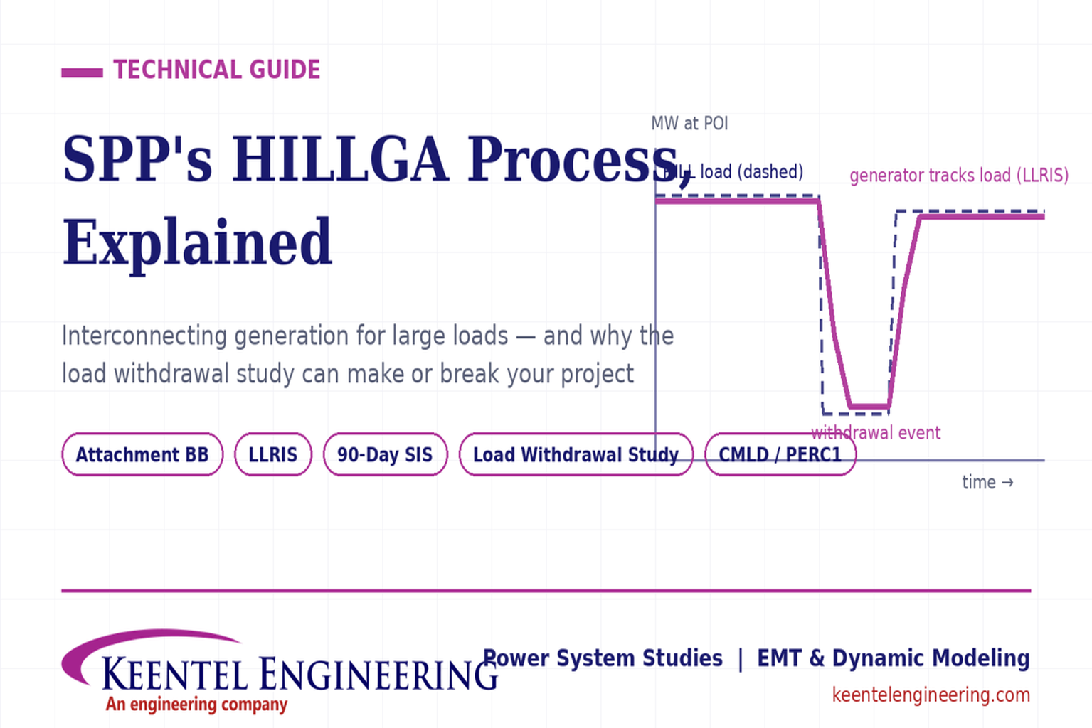
A HILLGA generator does not receive open access to inject power like a normal network resource. Its injection is tied to the supported HILL — the generator exists, in the tariff's eyes, to serve that load. This coupling is the source of both HILLGA's speed (the grid impact is bounded) and its most demanding engineering requirements (the generator must provably follow the load, including when the load suddenly disappears).
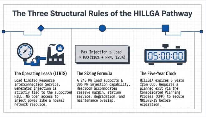
Three structural rules frame every HILLGA project:
The sizing formula
Under Attachment BB §3.1.1, the Maximum Injection Capability of a HILLGA request may not exceed the associated HILL's requested MW load multiplied by the higher of (a) 110% plus the seasonal Planning Reserve Margin in effect at submission, or (b) 125%. In practice: a 245 MW HILL can support a generating facility of roughly 306 MW or more of injection capability. That headroom exists for good reasons — reserve margin, station service, degradation, maintenance overlap — and using it well is a design optimization, not a formality.
The siting geometry
The generation must be local: the Point of Interconnection must be on the transmission system no more than two substations away from the HILL's Local Delivery Facilities ("HILLGA-Local"), and in the same SPP Deliverability Area as the HILL. One generating facility may support multiple HILLs, provided no more than five substations are involved and no more than two existing transmission line segments are utilized — a genuinely useful lever for multi-site campus strategies.
The five-year clock
The HILLGIA (the interconnection agreement HILLGA produces) has a service term of five years from the Commercial Operation Date. To keep operating beyond that — and to shed the load-limited leash — the customer must submit a full Interconnection Request in a subsequent Consolidated Planning Process (CPP) cycle, seeking Network Resource Interconnection Service (NRIS, with an expedited designation pathway available to SPP's Deliverability Areas) or Energy Resource Interconnection Service (ERIS). Treat HILLGA as a bridge with a hard expiration date, and plan the CPP entry early — not in year four.
One threshold question before anything else: is your generation even in the HILLGA lane? If the generating facility interconnects to facilities
not under SPP's functional control — behind the fence, on distribution, or to non-OATT transmission owner facilities — it follows the non-jurisdictional generation procedures of Business Practice 7250 §6.3 instead: transmission owner notification for units of 5 MW or more, potential Affected System Study Agreements with SPP, specification requirements (including whether a BESS will register as a Market Storage Unit), and SPP stability analysis under BP7250 §8. Choosing the wrong lane wastes months. Determining the right one is the first piece of advisory work on any co-located generation project.
How Keentel helps:
Keentel Engineering advises developers at the concept stage on HILLGA eligibility, the jurisdictional lane determination (Attachment BB vs. BP7250), injection sizing under the 110%+PRM/125% formula, siting geometry against the two-substation and Deliverability Area rules, and the CPP exit strategy — before deposits are paid and study clocks start.
Part 2: The Complete HILLGA Application Process, Step by Step
Step 0 — The prerequisite.
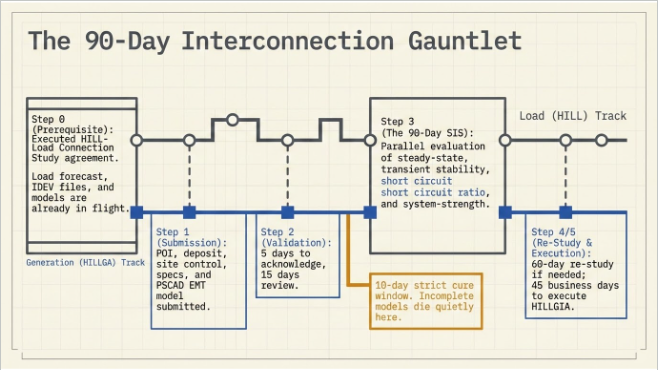
Before a HILLGA request can even be submitted, the customer must have planned load and supporting generation together with the Transmission Customer, resulting in an executed HILL-Load Connection Study agreement. In other words: the load-side HILL process (Attachment AQ, AX, or BA) comes first or in parallel. HILLGA is a companion process, not a standalone shortcut. Practically, this means the load's ten-year forecast, one-line, load models (CMLD/PERC1), and the Additional HILL Characteristics Form are already in flight — and the generation application must be consistent with all of it.
Step 1 — Assemble and submit the HILLGA request.
The submittal package includes the executed HILLGA study agreement, an identified Point of Interconnection for each request (compliant with the HILLGA-Local geometry), the required study deposit (scaled to requested MW under the filed fee structure — confirm current amounts in Attachment BB before wiring funds), site control evidence, and the technical data package: generator specifications, dynamic models, and — per SPP's explicit recommendation — a PSCAD EMT model at time of submission (more on why in Part 3).
Step 2 — Acknowledgment and validation.
SPP acknowledges the request within 5 business days, then conducts a 15-calendar-day review of the submission. If deficiencies are found, the customer has 10 business days to cure them. This is where incomplete model packages die quietly: a deficiency notice on your dynamic models doesn't just cost the cure window — it costs credibility and, if uncured, the request.
Step 3 — The 90-day System Impact Study.
Once validated, SPP performs the HILLGA SIS within 90 calendar days, evaluating steady-state performance, transient stability dynamics, short circuit ratio, and SCRCCT screening — the same system-strength gate as the load-side HDPS (SCR/WSCR/CSCR ≥ 6.0; CCT ≥ 0.15 s). In the same 90-day window, the host Transmission Owner performs its Facilities Analysis, and affected-system impacts are screened and studied as needed, with the customer and SPP coordinating with affected-system entities per the tariff.
If SCRCCT screening fails, EMT analysis is required outside the 90-day timeline.
This is the single biggest schedule risk in the process, and it is why SPP recommends the PSCAD model accompany the application: if the screen fails and your EMT model is already on file and validated, the supplemental analysis starts immediately instead of waiting months for model development.
Step 4 — Re-Study, if required.
If system conditions or project changes require it, SPP notifies the customer and performs a Re-Study within 60 calendar days.
Step 5 — Execute the HILLGIA.
After the study report, the customer has 45 business days to negotiate and execute the HILL Generator Interconnection Agreement, with its five-year-from-COD service term.
Step 6 — Plan the exit.
File the full Interconnection Request in a subsequent CPP cycle early enough that NRIS or ERIS is secured before the HILLGIA expires. The expedited designation pathway to SPP's Deliverability Areas exists — but only for those who plan for it.
End to end, a clean run from complete submission to executed HILLGIA is roughly seven to eight months. Every one of the words "complete," "validated," and "clean" is doing heavy lifting in that sentence — and all three depend on the quality of the models in the application.
Part 3: The Models CMLD, PERC1, PSCAD, and Why They Must Agree
A HILL + HILLGA project is studied as a coupled system: a large power-electronic load and its dedicated generation, sharing a small electrical neighborhood, evaluated by parallel 90-day studies. That demands a coherent model set:
CMLD (Composite Load Model)
The WECC composite load model represents the load facility as motor fractions, electronic load, and static load behind feeder/transformer equivalents, with protection-based tripping and reconnection. For a data center, the parameterization must capture the UPS-served electronic fraction, VSD-driven cooling, and the trip/reconnect thresholds that mirror SPP's HILL Fault Ride-Through Requirements.
PERC1 — SPP's preferred load model
PERC1 is the performance-based electronic load model built for power-electronic-dominant facilities. It directly parameterizes the behaviors SPP's requirements regulate: proportional load reduction during voltage sags, constant-current disturbance behavior, deep-sag transfer/trip logic, and the timed recovery ramp back to at least 90% of pre-disturbance consumption within one second of voltage recovery. SPP's HILL submittal guidance lists load modeling data as "CMLD and/or PERC1 (preferred)" — and on a HILLGA project, the load models matter twice, because the generator's studies are run against the load's behavior.
Generator dynamic models
The supporting generation needs its own RMS dynamic models (machine, exciter, governor, and plant controller for synchronous units; the applicable inverter models for BESS and solar) meeting SPP's model quality requirements, plus compliance alignment: IEEE 2800-2022 Clause 7 with SPP's decision points for inverter-based resources, PRC-024-4 for synchronous machines.
PSCAD EMT models
SPP recommends the PSCAD model at time of submission for exactly the reason described above — SCRCCT screening failure triggers EMT analysis outside the 90-day clock. For a coupled project, the EMT model should represent the integrated facility: the data center load (UPS front ends, cooling drives, protection logic), the generation (converters or machines with their full control stacks), and the shared network between them, capable of stable initialization, operation against Thévenin equivalents, impedance scans, and unbalanced fault simulation.
And they must agree with each other
SPP verifies RMS-vs-EMT model consistency. On a coupled project, inconsistency doesn't just delay one study — it can contaminate both the HDPS and the HILLGA SIS simultaneously. The load models, generator models, and EMT model should be developed as a matched set, benchmarked before submission, by a team that sees the whole system.
How Keentel helps:
Keentel Engineering develops the complete model set for HILL + HILLGA projects — CMLD and PERC1 load models parameterized from your actual equipment, generator dynamic models, and integrated PSCAD facility models — mutually benchmarked and packaged to SPP submittal formats, so both 90-day clocks start on time and neither study stalls on a model comment cycle.
Part 4: The Withdrawal Study Know Your Grid Headroom Before SPP Does
Every large-load interconnection ultimately turns on one number that nobody hands you:
how much power can this site actually withdraw from the transmission system, hour by hour, across a real year of grid conditions?
That number — the site's withdrawal capacity — is not the load's nameplate, and it is not a constant. It moves with seasonal facility ratings, system load levels, generation dispatch, and outage conditions.
A POI that supports 245 MW of withdrawal on a mild spring night may support far less on a peak summer afternoon with a line out of service.
The transmission owner and SPP will eventually tell you what the grid can deliver — in their study, on their clock, after your deposits are paid.
A withdrawal study answers the question first, on your side of the table.
A rigorous withdrawal study has three layers:
1. The Shadow Load Study (SLS)
Before submitting anything, replicate the analyses SPP and the host transmission owner will perform on your application: power flow with thermal and voltage screening at the POI, the applicable contingency set (aligned to NERC TPL-001-5.1 and SPP planning criteria), short circuit review, and system-strength indication consistent with SPP's SCRCCT methodology. The output is foresight — the expected study outcome, the binding constraints, the likely network-upgrade exposure, and whether SCRCCT screening (and therefore the supplemental EMT stage) is a live risk — all known before the 90-day clock starts and before the application locks in your requested MW.
2. The 8760 withdrawal-capacity model
Extend the SLS across the year: map representative system conditions — seasonal ratings, load levels, dispatch patterns, and outage states — onto all 8,760 hours to produce an hourly time series of the grid headroom available to your load. The deliverables that matter: the hourly withdrawal-capacity profile, its duration curve, and the deficit-hour analysis — the hours, depths, and durations when grid withdrawal capability falls short of the facility's demand.
3. BESS and generation sizing from the deficit hours
The deficit analysis converts directly into design: the behind-the-meter battery's power rating comes from the deepest deficits, its energy rating from the longest ones, and the dispatch strategy from their frequency and clustering. The same profile sizes on-site generation, shapes the phasing plan (how much load can energize in year one versus after upgrades), and — for a HILLGA project — informs the generator's operating envelope under LLRIS, where injection follows the load's forecast. This is the arithmetic of powered land development in a grid-constrained era: grid withdrawal capacity + BESS + behind-the-meter generation = firm capacity for a tenant, without waiting years for network upgrades.
Why does this analysis make or break projects?
Three reasons. First, it sets the application's requested MW intelligently — oversubscribe the POI and the study returns upgrade costs and delays that kill the pro forma; undersubscribe and you leave capacity, and revenue, on the table. Second, it converts study risk into design certainty: the BESS and generation are sized against measured headroom, not hope. Third, it collapses surprise: when SPP's HDPS or HILLGA SIS results arrive, a developer who ran the shadow study is confirming expectations and negotiating details — not discovering, five months and a deposit later, that the site supports half the load.
The dynamic dimension still matters
Withdrawal capacity is the planning layer; the dynamic behavior of withdrawal is the compliance layer. Under LLRIS, the co-located generator's injection is tied to the load — so when the load suddenly drops (a fault ride-through event, a UPS transfer during a deep sag, a feeder trip, or SPP's six-reclose sequences), the generator must run back fast and stably, without overspeed, overvoltage, or uncontrolled islanding — and then take the load back as it recovers to ≥90% of pre-disturbance consumption within one second of voltage recovery. A complete withdrawal study therefore pairs the 8760 planning analysis with EMT simulation of load-rejection and load-recovery events, verified runback and emergency power controls, and protection coordination across the load, generation, and transmission interface.
How Keentel helps:
Keentel Engineering performs the complete withdrawal study stack — Shadow Load Studies replicating SPP/TO methodology, 8760 hourly withdrawal-capacity modeling with deficit-hour analysis and BESS power/energy sizing, and the dynamic load-rejection and runback verification that LLRIS projects must ultimately demonstrate — so your application is sized right, your storage is sized right, and SPP's study results arrive as confirmation, not surprise.
Part 5: Seven Pitfalls We See in HILLGA Planning
Submitting the HILLGA request before the HILL-Load Connection Study agreement exists.
The prerequisite is structural — the request isn't valid without it.
Sizing the generator to the load's nameplate instead of the formula.
The 110%+PRM/125% headroom is there to be used; leaving it unexamined strands optionality.
Skipping the PSCAD model at submission.
f SCRCCT screening fails — likely in weak areas — EMT analysis outside the 90-day clock begins only when a model exists.
Treating load models and generator models as separate workstreams.
SPP studies a coupled system; inconsistent models stall both studies at once.
Applying without a withdrawal study.
Requesting MW the POI cannot support — or failing to demonstrate stable generator behavior through load-rejection events — invites upgrade shocks, comment loops, and restudies.
Ignoring the jurisdictional lane question.
Behind-the-fence and distribution-connected generation may belong in BP7250's non-jurisdictional process, not Attachment BB — with entirely different steps.
Deferring the CPP exit plan.
Five years arrives quickly; NRIS/ERIS conversion, potential network upgrades, and the expedited designation pathway should be scoped at financial close.
Technical FAQ
Q1: What exactly is HILLGA, in one paragraph?
HILLGA (High Impact Large Load Generator Assessment) is SPP's expedited interconnection study pathway, under Attachment BB of the SPP Tariff, for generation dedicated to serving a specific High Impact Large Load — a facility with peak demand of at least 10 MW at 69 kV or below, or 50 MW above 69 kV. SPP performs a System Impact Study within 90 calendar days of a validated request, the transmission owner performs its Facilities Analysis in parallel, and the resulting interconnection agreement (HILLGIA) grants Load Limited Resource Interconnection Service — injection tied to the supported load — for a term of five years from commercial operation, after which the generator transitions to SPP's standard Consolidated Planning Process for full interconnection service.
Q2: How big can our supporting generation be relative to our load?
The Maximum Injection Capability may not exceed the HILL's requested MW load multiplied by the higher of (a) 110% plus the seasonal Planning Reserve Margin in effect at submission, or (b) 125%. For a 245 MW load, that's at least ~306 MW of permissible injection capability. Note this is the sizing ceiling; actual permitted injection under LLRIS is governed by the supported load's demand. The gap between nameplate, injection capability, and hourly permitted output is exactly where thoughtful engineering — reserve strategy, BESS pairing, maintenance planning — creates value.
Q3: Where can the generation be located?
The Point of Interconnection must be on the transmission system no more than two substations away from the HILL's Local Delivery Facilities, and in the same SPP Deliverability Area as the HILL. One generating facility may support multiple HILLs if no more than five substations are involved and no more than two existing transmission line segments are utilized. Siting outside this geometry doesn't just weaken the application — it makes the request ineligible for the pathway.
Q4: What does the 90-day HILLGA System Impact Study actually evaluate?
Steady-state performance (thermal and voltage), transient stability dynamics, short circuit ratio, and SCRCCT screening — SPP's system-strength gate combining short-circuit-ratio metrics with critical clearing time. During the same 90 days, the host transmission owner performs its Facilities Analysis and affected-system impacts are evaluated and studied as needed. If a re-study is triggered, SPP performs it within 60 calendar days.
Q5: What happens if SCRCCT screening fails?
Detailed EMT (electromagnetic transient) analysis is required — outside the 90-day study timeline. This is the pathway's biggest schedule trap, and it's why SPP explicitly recommends providing a PSCAD model at the time of submission: with a validated model already on file, the supplemental analysis begins immediately rather than after months of model development. For power-electronic-heavy projects (data center loads, BESS, solar), prudent planning assumes the supplemental stage is possible and builds the EMT model supplemental-ready from day one.
Q6: Why do CMLD and PERC1 load models matter to a generation application?
Because the HILLGA studies evaluate the generator serving that specific load — the load's dynamic behavior is an input to the generator's studies. CMLD represents the facility as a composite of motors, electronic load, and static load with protection-based tripping; PERC1, SPP's preferred model for power-electronic-dominant loads, directly parameterizes sag response, constant-current disturbance behavior, transfer/trip logic, and the mandated one-second recovery ramp. If the load models misrepresent ride-through or recovery behavior, the generator's stability and withdrawal analyses inherit the error — and SPP's RMS-vs-EMT consistency verification will eventually surface it, at the worst possible time.
Q7: What is a withdrawal study, and why does Keentel emphasize it so heavily?
It is the determination of how much power your facility can actually withdraw from the transmission system — resolved hour by hour, before you apply. The full stack has three layers: a Shadow Load Study that replicates the power flow, contingency, short circuit, and system-strength analyses SPP and the transmission owner will run on your application; an 8760 model that maps seasonal ratings, dispatch, and outage conditions onto every hour of the year to produce a withdrawal-capacity time series with duration curves and deficit-hour analysis; and design conversion — sizing the behind-the-meter BESS (power from the deepest deficits, energy from the longest), shaping the generation strategy, and setting the application's requested MW. For LLRIS projects, the study extends to the dynamic layer: EMT simulation of load-rejection events (including SPP's six-reclose sequences and the one-second load-recovery step), generator runback and emergency power control verification, and anti-islanding review. We emphasize it because it is the highest-leverage spend in the entire process: it prices the site's true capacity before deposits are paid, sizes the storage against measured headroom rather than assumptions, and turns SPP's eventual study report from a risk event into a confirmation.
Q8: Our generation will be behind the fence / connected at distribution. Does HILLGA even apply?
Maybe not — and this is a threshold determination worth getting right before spending anything. Generation interconnecting to facilities not under SPP's functional control follows the non-jurisdictional generation procedures of Business Practice 7250 §6.3 instead: the transmission owner notifies SPP of units of 5 MW or more, may require an Affected System Study Agreement with SPP, requires specifications for the new resource (including whether a BESS is intended to register as a Market Storage Unit), and SPP performs stability analysis per BP7250 §8 within a 90-day timeframe at the TO's request. The two lanes have different applications, different studies, and different agreements. Keentel performs this lane determination as a first-step advisory task.
Q9: What does the application package need to contain?
The executed HILLGA study agreement; an identified, geometry-compliant Point of Interconnection for each request; the required study deposit (scaled to requested MW — confirm current amounts against Attachment BB); site control evidence; the generator technical data and dynamic models; and, per SPP's recommendation, a PSCAD EMT model. Behind it all sits the prerequisite: an executed HILL-Load Connection Study agreement demonstrating that load and generation were planned together with the Transmission Customer. SPP acknowledges within 5 business days, reviews for 15 calendar days, and allows 10 business days to cure deficiencies — a tight window that rewards a complete, internally consistent package.
Q10: What happens after the study — and after five years?
Following the study report, the customer has 45 business days to negotiate and execute the HILLGIA, which carries a five-year service term from the Commercial Operation Date. To continue operating beyond that term — and to shed the load-limited restriction — the customer submits a full Interconnection Request in a subsequent Consolidated Planning Process cycle, seeking NRIS (with an expedited designation pathway available to SPP's Deliverability Areas) or ERIS. The CPP conversion can carry network upgrade exposure, so the exit analysis belongs in the original project pro forma, not in year four.
Q11: How do the HILL (load) and HILLGA (generation) processes fit together on one project timeline?
They are designed to run in parallel, with the load side leading: the HILL-Load Connection Study agreement is a prerequisite to the HILLGA request. A well-run coupled project synchronizes the two — one integrated data room, one consistent ten-year forecast, one matched model set (CMLD/PERC1 + generator models + integrated PSCAD), and one coordination channel to SPP and the transmission owner — so that the two 90-day studies proceed on consistent assumptions and neither becomes the other's critical path. Fragmenting the work across uncoordinated consultants is how coupled projects acquire inconsistent models and serial study delays.
Q12: What can Keentel Engineering take off our plate, end to end?
The complete application lifecycle: pathway strategy and lane determination (Attachment BB vs. BP7250); siting and sizing analysis under the HILLGA-Local geometry and the 110%+PRM/125% formula; assembly of both the HILL and HILLGA application packages, including the Additional HILL Characteristics Form, forecasts, and IDEV files; the full model set — CMLD and PERC1 load models, generator dynamic models, and integrated, supplemental-stage-ready PSCAD models, mutually benchmarked; the dedicated withdrawal study — Shadow Load Study, 8760 withdrawal-capacity modeling and BESS sizing, plus load rejection, runback/EPC demonstration, and structural scenario analysis; fault ride-through and IEEE 2800-2022 / PRC-024-4 compliance alignment; study-cycle coordination with SPP, the transmission owner, and affected systems through deficiency cures, comment responses, and re-studies; and the five-year exit — CPP interconnection request preparation and NRIS/ERIS conversion strategy. All work is performed under the responsible charge of a licensed Professional Engineer.
How Keentel Engineering Supports HILL + HILLGA Projects
Keentel Engineering provides end-to-end engineering and application support for large loads and their supporting generation across SPP and North American markets:
- Complete SPP application assistance — HILL (Attachment AQ/AX) and HILLGA (Attachment BB) submittal packages, prerequisite sequencing, deficiency-cure support, and study-cycle coordination through HILLGIA execution.
- Withdrawal studies — our signature analysis for grid-constrained development: Shadow Load Studies replicating SPP/TO methodology, 8760 hourly withdrawal-capacity modeling with deficit-hour analysis and BESS power/energy sizing, plus the dynamic layer — load-rejection EMT simulation, generator runback and emergency power control demonstration, reclosing-sequence stability, and anti-islanding verification.
- Dynamic load modeling — CMLD and PERC1 — site-specific parameterization encoded to SPP's HILL Fault Ride-Through Requirements, delivered in SPP submittal formats with Business Practice 7850 documentation.
- PSCAD EMT modeling — integrated load + generation facility models, supplemental-stage-ready (Thévenin operation, impedance scans, unbalanced faults, energization), validated and benchmarked against the RMS models.
- Generator interconnection engineering — RMS dynamic models, IEEE 2800-2022 Clause 7 and PRC-024-4 compliance alignment, and SCRCCT risk assessment at the POI.
- Strategy and exit planning — LLRIS operating envelope analysis, forecast sensitivity, and CPP conversion (NRIS/ERIS) roadmaps aligned to the five-year HILLGIA term.
With a 32-engineer organization, P.E. services in all 50 states, and recent large-load engagements from 50 MW to 1 GW across ERCOT, CAISO, and PJM, Keentel brings data-center-scale modeling experience to the newest — and fastest — interconnection pathway in SPP.
Planning a co-located generation project — or already staring at a deficiency notice?
Contact Keentel Engineering at contact@keentelengineering.com or 813-389-7871, or visit keentelengineering.com to schedule a technical consultation.
Our Offices:
- Head Office – Tampa, FL: 400 N Ashley Dr, STE #2600, Tampa, FL 33602 · (813) 389-7871
- Austin, TX: 5900 Balcones Drive, STE 100, Austin, TX 78731 · (512) 591-0752
- Sacramento, CA: 1401 21st St, Ste R, Sacramento, CA 95811 · (916) 913-4524
- Baltimore, MD: 306 W Redwood St, STE 200, Baltimore, MD 21201 · (410) 225-2181
This article reflects the SPP HILLGA framework as filed October 24, 2025 and approved by FERC in January 2026, based on SPP's published HILLGA overview (Attachment BB), the HILL process documents (RR696/RR720/RR724), and SPP's HILL Fault Ride-Through Requirements (V2.0). Deposit amounts, forms, and procedural details continue to evolve through the SPP stakeholder process — always confirm current requirements against Attachment BB, Business Practice 7250, and SPP's OASIS studies page before submitting. This article is general information, not legal or financial advice.

About the Author:
Sandip "Sonny" R. Patel, P.E.
IEEE Senior Member · Founder & CEO, Keentel Engineering
In 1995, Sonny Patel earned his Electrical Engineering degree from the University of Illinois. But degrees don't build legacies — action does.
For three decades, he has worked the power industry from every side of the table: 16 years as a utility engineer at Exelon/Commonwealth Edison; generation leadership across hydroelectric, industrial steam turbine, and a 9 GW renewable fleet; NERC Regional Entity Senior Compliance Engineer and Audit Team Lead, auditing some of the nation's largest utilities; and testing and commissioning lead on equipment up to 765 kV — the very top of the North American grid.Utility. Generator. Regulator. Consultant. Few engineers have seen all four seats. Fewer still have sat in them.
His experience spans nuclear, hydro, conventional generation, renewables, oil and gas, mining — and today's data centers, where he is authoring a three-book series on data center design. He is a Licensed Professional Engineer in six states and a Licensed Electrical Contractor in Florida (Unlimited EC) — he doesn't just design the work; he's qualified to stand behind its execution.Today, as Founder and CEO of Keentel Engineering, Sonny leads a nationwide team of engineers delivering substation design, power system studies, NERC compliance, and commissioning — done right, coast to coast.Three decades. Every side of the table. One standard: accountable engineering.
Services

Let's Discuss Your Project
Let's book a call to discuss your electrical engineering project that we can help you with.
About the Author:
Sandip "Sonny" R. Patel, P.E.
IEEE Senior Member · Founder & CEO, Keentel Engineering
In 1995, Sonny Patel earned his Electrical Engineering degree from the University of Illinois. But degrees don't build legacies — action does.
For three decades, he has worked the power industry from every side of the table: 16 years as a utility engineer at Exelon/Commonwealth Edison; generation leadership across hydroelectric, industrial steam turbine, and a 9 GW renewable fleet; NERC Regional Entity Senior Compliance Engineer and Audit Team Lead, auditing some of the nation's largest utilities; and testing and commissioning lead on equipment up to 765 kV — the very top of the North American grid.
Utility. Generator. Regulator. Consultant. Few engineers have seen all four seats. Fewer still have sat in them.
His experience spans nuclear, hydro, conventional generation, renewables, oil and gas, mining — and today's data centers, where he is authoring a three-book series on data center design. He is a Licensed Professional Engineer in six states and a Licensed Electrical Contractor in Florida (Unlimited EC) — he doesn't just design the work; he's qualified to stand behind its execution.
Today, as Founder and CEO of Keentel Engineering, Sonny leads a nationwide team of engineers delivering substation design, power system studies, NERC compliance, and commissioning — done right, coast to coast.Three decades. Every side of the table. One standard: accountable engineering.
Leave a Comment
Thank you for contacting us.
We will get back to you as soon as possible.
We will get back to you as soon as possible.
Oops, there was an error sending your message.
Please try again later.
Please try again later.
Related Posts

By Team 2 Dexora
•
October 20, 2026
Explore grounding system testing with Keentel Engineering. Learn IEEE 80/81 methods, soil resistivity, ground resistance, and touch and step voltage safety.

By SANDIP R PATEL
•
October 13, 2026
Plan data center capacity with land screening, MW-per-acre estimates, grid power availability and interconnection feasibility studies from Keentel Engineering.

By SANDIP R PATEL
•
October 11, 2026
Learn which fault produces the highest current at a bus, why SLG faults can exceed three-phase faults, and how symmetrical components determine fault duty.

By SANDIP R PATEL
•
October 11, 2026
Learn why zero-sequence current pulsates in the dq0 frame, how Park's transformation works, and how inverter controls handle unbalance and ground faults.

By SANDIP R PATEL
•
October 11, 2026
Explore grid inertia, RoCoF and frequency response, with swing equation calculations, frequency nadir analysis and US power system simulation examples.

By SANDIP R PATEL
•
October 11, 2026
Learn transient stability analysis, swing equation, equal-area criterion and critical clearing time with a 345 kV worked example and NERC TPL-001 guidance.

By SANDIP R PATEL
•
October 11, 2026
Learn why inverter controls become unstable in weak grids, how PLL bandwidth and SCR affect stability, and how PSCAD EMT studies identify and mitigate oscillations.

By SANDIP R PATEL
•
October 11, 2026
Learn how STATCOMs improve voltage stability and prevent FIDVR. Explore reactive power sizing, delayed fault clearing, NERC criteria and 138 kV simulation results.

By SANDIP R PATEL
•
October 10, 2026
Learn BESS DC sizing with power, energy, current and C-rate calculations, battery losses, degradation and a 100 MW/400 MWh utility-scale example.





