A Coordinated Electric System Interconnection Review—the utility’s deep-dive on technical and cost impacts of your project.
Challenge: Frequent false tripping using conventional electromechanical relays
Solution: SEL-487E integration with multi-terminal differential protection and dynamic inrush restraint
Result: 90% reduction in false trips, saving over $250,000 in downtime
| Category | Metric |
|---|---|
| VPP capacity (Lunar Energy) | 650 MW |
| Lunar funding raised | US$232 million |
| Data center BESS example | 31 MW / 62 MWh |
| ERCOT grid-scale batteries | 15+ GW |
| LDES tenders (H1 2026) | Up to 9.3 GW |
| Lithium-ion share of LDES by 2030 | 77% |
| FEOC initial threshold | 55% |
| BESS tariff rate (2026) | ~55% |
| Capacity gain from analytics | 5–15% |
What is T&D Co-Simulation?
Confusing Physical Connections with Logical Nodes in IEC 61850
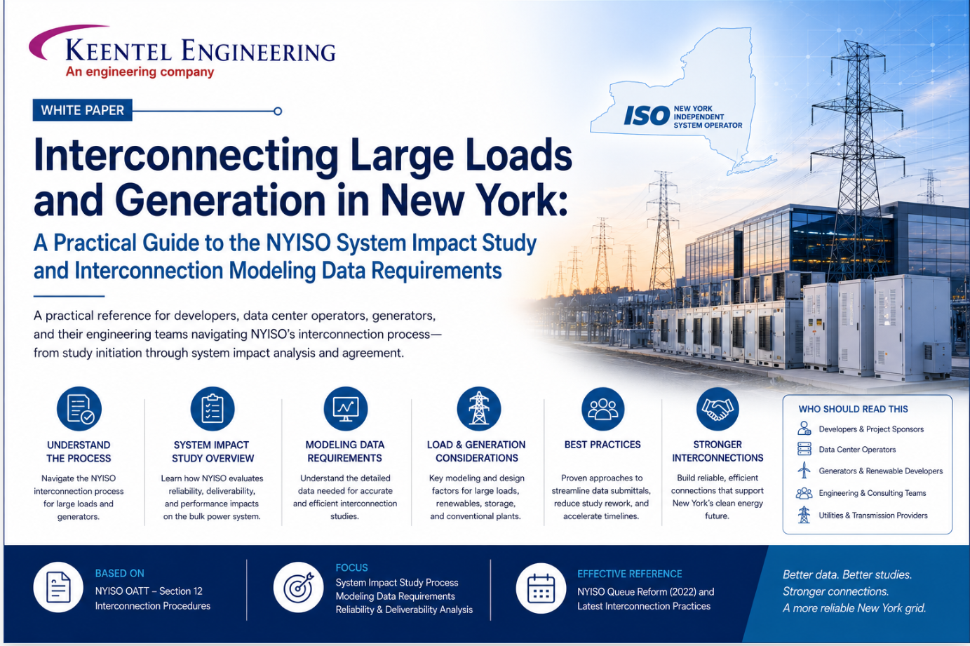
Interconnecting Large Loads and Generation in New York
Jun 10, 2026 | blog
1. Why interconnection has become the critical path
For most of the last two decades, the hardest part of building a large electrical facility in New York was permitting, real estate, or financing. That has changed. Today, the single most common reason a large load or generation project slips its schedule is the interconnection queue. The grid is being asked to absorb an unprecedented wave of new demand — hyperscale and AI data centers, electrified industrial processes, hydrogen electrolyzers — at the same time it is integrating large volumes of inverter-based generation and storage. The New York Independent System Operator (NYISO) is the gatekeeper for the bulk of that activity, and its studies now sit squarely on the critical path.
The encouraging news is that the process is far more navigable than it first appears. The requirements are documented, the data formats are standardized, and the points where projects stall are predictable. A customer who understands the System Impact Study (SIS) workflow and who arrives with a clean, validated modeling package can move through the process months faster than one who treats data assembly as an afterthought. This whitepaper distills the governing NYISO procedures into a working guide, and flags the places where engineering rigor pays for itself.
Three documents, one process
NYISO Technical Bulletin 266 (Nov 2025) — the supplemental procedure for the Load interconnection System Impact Study.
NYISO Transmission Expansion and Interconnection (TEI) Manual (Manual 23, v4.3) — the governing manual whose Section 3.5 sets the Load interconnection procedure that TB-266 supplements.
Modeling Guideline for NYISO Interconnection Data (v10) — the detailed technical specification for the steady-state, short-circuit, and stability models every interconnection customer must submit.
2. The regulatory landscape: where the rules live
NYISO interconnection requirements are spread across several layers, and knowing which layer governs your project prevents a great deal of wasted effort. At the top is the NYISO Open Access Transmission Tariff (OATT) — the FERC-jurisdictional document that carries the binding rules. The interconnection procedures themselves were substantially rewritten in response to FERC Order No. 2023. On May 1, 2024, NYISO filed extensive revisions that established new Standard Interconnection Procedures in Attachment HH of the OATT, replacing the older Large Facility and Small Generator procedures previously found in Attachments S, X, and Z.
Below the tariff sit the NYISO manuals and technical bulletins, which translate tariff requirements into working procedure. The TEI Manual (Manual 23) is the principal interconnection manual. Importantly, while most of its Section 3 interconnection content no longer applies to projects entering the new Standard Interconnection Procedures, its Section 3.5 — Load Interconnection Procedures — continues to govern load projects. That is the hook that Technical Bulletin 266 hangs on: TB-266 supplements the existing tariff requirements in OATT Section 3.9 and the TEI Manual for the Load SIS, and NYISO has signaled that tariff changes to the Load interconnection process are being contemplated as part of a 2026 project initiative. In other words, the load process described today is current but explicitly transitional, and customers should expect refinement.
For generation, storage, and other resources entering a Cluster Study under Attachment HH, the Modeling Guideline for NYISO Interconnection Data is the controlling technical specification. It defines the exact files, software versions, naming conventions, and performance tests that a project model must satisfy. Although it is written for cluster-study generation customers, much of its modeling discipline — software versions, data formats, validation expectations — is exactly what load customers will be expected to mirror for their own SIS.
3. Does your project even fall under NYISO?
The first question is jurisdictional. Not every
large load triggers a NYISO study. The NYISO Load interconnection procedures apply to load interconnections that are either greater than 10 MW connecting at a voltage level of 115 kV or above, or 80 MW or more connecting at a voltage level below 115 kV. This includes uprates to existing or previously planned load projects. Proposed load interconnections that fall outside those criteria are not subject to the NYISO procedures; instead they fall under the Transmission Owner's procedures.
| Connection voltage | Load size threshold | Who governs the study |
|---|---|---|
| 115 kV and above | Greater than 10 MW | NYISO Load interconnection procedures |
| Below 115 kV | 80 MW or more | NYISO Load interconnection procedures |
| Below 115 kV | Under 80 MW | Connecting Transmission Owner's procedures |
| 115 kV and above | 10 MW or less | Connecting Transmission Owner's procedures |
Proposed load interconnections that fall outside those criteria are not subject to the NYISO procedures; instead they fall under the Transmission Owner's procedures.Two practical points follow. First, a project's voltage level and size should be confirmed early, because they determine whether you are dealing with NYISO at all. Second, the threshold captures uprates — so an expansion of an existing facility can pull the whole site into the NYISO process even if the original load did not. A prior phase that was studied under the Transmission Owner's process because it sat below the threshold may need to be disclosed and characterized when the cumulative load crosses the line.
4. What NYISO actually does in a Load SIS — and what it does not
It is essential to set expectations correctly. In the Load interconnection process, NYISO's role is narrow and specific: it determines the reliability impacts of the load project on the system through the System Impact Study. The Load SIS is informational and non-binding. Once the SIS is complete and the customer has paid for the technical study, NYISO's role in the load interconnection process concludes.
After that, the project does not stop — it shifts to the Connecting Transmission Owner (CTO). The customer may elect to proceed with the CTO on the facility studies and then enter into a two-party interconnection agreement. NYISO is not a party to interconnection agreements for load interconnections. This two-stage structure — NYISO for the reliability assessment, the CTO for facilities and the contract — is one of the most frequently misunderstood aspects of the load process, and it has direct scheduling consequences: the work does not end when the SIS report is issued.
NYISO may also identify potentially Affected Transmission Owners (ATOs) or Affected Systems. These parties can review project information, including the study base cases, and the SIS results will be reviewed with them if the study determines they are in fact affected by the load project. For a project near a system boundary, this can widen the circle of reviewers and should be anticipated in the schedule.
5. Before you file: preparation that de-risks the schedule
The most leverage a customer has over its own timeline is exercised before the request is ever submitted. NYISO and the TEI Manual both emphasize early coordination with the CTO. In that coordination the customer should accomplish two things: determine the proposed Point of Interconnection (POI), including the substation or transmission line name and voltage level; and discuss a preliminary plan for the local upgrades that will be required at the POI.
To have a Load Interconnection Request deemed complete, the customer must submit two items through the NYISO interconnection portal: a completed interconnection request form, and a project conceptual one-line showing the project up to the POI with the POI clearly labeled. Those two deliverables sound modest, but a vague or unlabeled one-line is a common reason a request is not deemed complete.
Access control matters too. All project contacts should obtain CEII (Critical Energy/Electric Infrastructure Information) access and, where required, execute the CTO's confidentiality agreement before the project scoping call. NYISO typically schedules that scoping call within about two weeks of determining the request is complete, and any attendee lacking CEII access and an executed confidentiality agreement will be asked to leave before power system information is discussed. The fix is simple but easy to forget: clear your whole technical team for CEII well ahead of the call.
5.1 Characterizing the load
Before the SIS scope is finalized, NYISO requires the customer to characterize the project in detail. This is not a formality; the characterization shapes how the load is modeled and which sensitivities are run. Required detail includes:
- Category and characteristics of the load. For example: data centers and other computational load (traditional, AI training or inference, or cryptocurrency mining); industrial loads (mining and mineral processing, metals and heavy manufacturing, semiconductor and electronics manufacturing, chemical and petrochemical processing, or oil and gas production); hydrogen production facilities; or other categories.
- Load flexibility. Whether the load would reduce output during peak load periods — for how long, how many times, and whether the customer is willing to participate in NYISO's Distributed Energy Resource program.
- Daily and seasonal load profile. How the load behaves across the day and across seasons.
- Existing or previously planned prior-phase load. Including load below the NYISO threshold that was previously studied under the CTO process.
- Phased in-service plans. Expected dates and the accompanying MW levels for each phase.
- Power flow, dynamics, and short circuit modeling data. Provided in the requested format (discussed in detail in Section 8).
Two NYISO forms support this stage and can be reviewed in advance: the Modeling Data Summary of NYISO Interconnection Data (a generic interconnection form, so some fields may not apply to a load project) and the Load Interconnection Data Request Form. NYISO recommends that the customer have at least one project contact who is fluent in power system analysis software — specifically Siemens PSS®E and ASPEN OneLiner™ — because the modeling deliverables are produced and validated in those tools.
5.2 The study agreement and the deposit
Two commercial milestones gate the start of the study. The customer must execute the System Impact Study Agreement (SISA) within 30 days of receipt, and must submit a $150,000 study deposit before the SIS begins. The deposit is a true-up, not a fixed price: if actual study costs at finalization are less than $150,000, the customer is reimbursed the difference; if they exceed it, the customer is billed the difference. Those costs can include NYISO's use of contractors or consultants and computation services, and costs the CTO incurs. Budgeting should therefore treat $150,000 as a floor with upside, not a cap.
6. Inside the study: base cases, bundling, and adverse impacts
6.1 How the base case is built
The base system representation for a Load SIS is a year-five representation as approved by the NYISO Operating Committee, consistent with a recent NYISO planning study such as the latest Short-Term Assessment of Reliability (STAR). In limited circumstances, NYISO may run sensitivities to the base case — for example, to include other load projects that do not meet the STAR inclusion rules, or to model other load projects at their full requested level — but only where those other projects are in close electrical proximity to the POI and are expected to contribute to the adverse reliability impacts identified in the study. The practical implication is that your project is not studied in isolation: nearby pending load is part of the picture when it could compound an impact.
6.2 Bundling related projects
Where appropriate, NYISO will model several projects in the same post-project case if the projects are moving forward in the same time frame and could cumulatively contribute to the same adverse reliability impacts. Bundling streamlines administrative tasks — scope development, stakeholder presentation, base case and study file development — and lets the incremental impact of each project be studied efficiently. Crucially, if the analysis identifies violations of Applicable Reliability Requirements, the SIS will still identify the individual contribution of each project. Bundling does not blur accountability; it just avoids studying the same neighborhood from scratch several times over.
6.3 When the study finds an adverse impact
If the SIS finds that the project as proposed would cause adverse reliability impacts, NYISO performs further analysis to identify alternatives that eliminate the impact. Those alternatives may include potential Network Upgrades or changes to the project itself, and consideration is given to the load ramp-up schedule — because an impact may appear before the project reaches its full requested load. Everything identified here is informational and non-binding. Importantly, the SIS does not provide good-faith cost-and-schedule estimates for those Network Upgrades; those are developed later, during the facility study with the CTO.
7. Timeline, transparency, and the steps after the SIS
Under the current process, NYISO gives a conservative estimate of nine months from the customer's study selection to SIS completion. That figure includes both administrative items and the technical studies, and NYISO is explicit that it is informational only. Real schedules vary widely depending on how quickly project modeling information is validated, when the study commences, the extent of any adverse reliability impacts, and the complexity of any required Network Upgrades. The lesson is consistent with everything above: the variable a customer can most influence is the speed and quality of data validation.
Once the SIS commences, the customer and applicable CTOs can track progress through the NYISO interconnection portal, which provides weekly updates and an interactive Gantt chart of high-level tasks against time. This visibility is genuinely useful for coordinating downstream activities — equipment procurement, CTO engagement, financing milestones.
After the SIS, the project must complete a facilities study and an interconnection agreement with the CTO before it can go in service. Customers should engage the CTO early to understand its facility study process. One subtlety deserves emphasis: the system representation used for the facility study may differ from the one used in the SIS, which can lead to differences in the Network Upgrades each study identifies. A clean SIS result is necessary but not sufficient — the facility study can still surface new details.
| Stage | Owner | Output / status |
|---|---|---|
| Pre-filing coordination | Customer + CTO | POI defined; conceptual one-line; CEI accessI |
| Request deemed complete | NYISO | Scoping call scheduled (~2 weeks) |
| SISA + deposit | Customer | SISA in 30 days; $150,000 deposit |
| System Impact Study | NYISO + CTO | Reliability assessment; ~9 months (conservative) |
| SIS report issued | NYISO | Informational, non-binding; NYISO role concludes |
| Facilities study | CTO | Detailed facilities + upgrade costs/schedule |
| Interconnection agreement | CTO + Customer | Two-party agreement; NYISO not a party |
8. The modeling data package: where projects win or lose time
If there is a single theme across NYISO's guidance, it is that a complete, correctly formatted, validated model is the fastest path through the process. The Modeling Guideline for NYISO Interconnection Data spells out the package for cluster-study projects, and its discipline is the benchmark for the data a load customer must provide. A complete modeling data package has four parts: a one-line diagram, a steady-state model, a short-circuit model, and a dynamic (stability) model. Each has specific software-version and file-format requirements.
| Model | Tool & version | Required files |
|---|---|---|
| One-line diagram | Professional engineering drawing | POI clearly labeled with station/line names; general electrical components shown |
| Steady state | Siemens PSS®E v35.3.3 | .sav or .raw, .idv (batch format), .sld |
| Short circuit | ASPEN OneLiner™ v15.7 | .olr, .chf |
| Dynamics / stability | PSS®E (v35.3.3 / 35.5.3 family) | .dyr; user-written models add .dll + source as applicable |
8.1 Steady-state modeling essentials
The steady-state model should be aggregated wherever possible, using the fewest equivalent buses and generators — ideally one equivalent generator per resource type. NYISO publishes a strict bus-naming convention (the customer leaves a placeholder cluster number, and NYISO fills it in) and reserves bus numbers 888000 through 888999 for the project, which NYISO renumbers when adding the project to the post-project case. A few rules trip up newcomers repeatedly:
- Implicit transformers inside a generator are not allowed; the GSU and PSU must be modeled explicitly, with Rtran and Xtran set to zero on the machine.
- Generator P and Q limits must reflect the actual operating point and meet the OATT power-factor requirement of +/- 0.95 — measured at the POI for synchronous resources, or at the PSU high side for inverter-based resources.
- Pgen in the submitted .idv should be set to zero; NYISO dispatches the project itself.
- Transformer impedances follow a defined base convention: GSU impedances on the nameplate MVA, PSU impedances on the self-cooled MVA rating.
8.2 Short-circuit modeling essentials
Short-circuit models are built in ASPEN OneLiner™. Inverter-based generators are modeled as a Voltage-Controlled Current Source (VCCS) injecting reactive current only; synchronous machines are modeled as conventional generation. Per the NYISO TEI Manual, loads and shunts are ignored in short circuit and are excluded from the model. NYISO publishes its exact ASPEN solution settings (subtransient generator impedance, prefault voltage from a linear network solution, enforce current limits, simulate converter-interfaced resources and VCCS, and so on). The acceptance check is concrete: the project model must inject fault current into single-phase, two-phase, and three-phase-to-ground faults at the POI, and must create no network anomalies.
8.3 Stability modeling and ride-through
Stability models must use PSS®E standard library models wherever possible; a user-written model is permitted only with documentation showing that no standard library model fits, and only from a model series already accepted by the MMWG. The stability package is where two of the most important grid-protection standards are enforced:
- NERC PRC-024 ride-through. Protection settings in the .dyr file are checked against the PRC-024 voltage and frequency “no-trip” zones. The settings must reflect the plant's actual intended protection — they must not simply mimic the minimum requirement. A relay that trips before the required minimum time sits inside the no-trip zone and is non-compliant.
- CTO-specific requirements (e.g., LIPA / PSEG-LI). Some Transmission Owners impose stricter ride-through than PRC-024, with larger no-trip zones and additional dynamic requirements such as smooth reactive-current injection and a specified active-power recovery rate after a fault. Projects in those territories must meet the stricter standard.
Model usability is then proven with defined tests: a 20-second flat (no-fault) run that must hold steady within tight tolerances and trip no units, and a 9-cycle three-phase fault at the POI after which the system must remain stable, no unit may trip, and generator voltages must return to at least 0.9 per unit within five seconds of fault clearing. A model that fails these tests is sent back, and the clock keeps running.
Keentel's practical takeaways
Confirm jurisdiction first — voltage and MW determine whether NYISO or the CTO governs.
Treat the conceptual one-line and POI definition as gating deliverables, not formalities.
Clear the entire technical team for CEII before the scoping call.
Budget the $150,000 deposit as a floor; actual costs true up in both directions.
Build models to the exact software versions, naming conventions, and base conventions — version mismatches cause avoidable rejections.
Make protection settings reflect real plant design, and pre-test against PRC-024 and any CTO-specific ride-through before submission.
Plan for the post-SIS CTO phase from day one — the SIS is informational, and the binding agreement is with the CTO.
9. How Keentel Engineering helps
Keentel Engineering supports load and generation customers across the full interconnection lifecycle: jurisdictional screening and POI strategy, conceptual one-line and request-package preparation, load characterization and flexibility analysis, and the assembly and validation of steady-state, short-circuit, and stability models to NYISO's exact specifications. We pre-run the model usability and ride-through checks NYISO will run, so issues are caught before submission rather than mid-study. And because NYISO's role ends at the SIS, we help carry the project into the CTO facilities study and interconnection agreement with continuity of engineering and modeling. The objective is simple: keep interconnection off the critical path.
Frequently Asked Questions
The answers below summarize current NYISO procedure for the Load interconnection System Impact Study and the modeling-data expectations that accompany it. Procedures are subject to change — NYISO has indicated that tariff changes to the Load interconnection process are being contemplated as part of a 2026 initiative — so confirm specifics against the current OATT, TEI Manual, and applicable Technical Bulletins before relying on them for a live project.
Q1. Which load projects must go through the NYISO interconnection process?
The NYISO Load interconnection procedures apply to load interconnections that are either greater than 10 MW connecting at 115 kV or above, or 80 MW or more connecting below 115 kV. This includes uprates to existing or previously planned load. Projects that fall outside those thresholds are not subject to the NYISO procedures and instead fall under the Connecting Transmission Owner's (CTO's) procedures. Because the threshold captures uprates, an expansion can pull an entire site into the NYISO process even if the original load did not qualify.
Q2. What is a System Impact Study (SIS), and is its outcome binding?
The SIS is NYISO's evaluation of the reliability impacts of a proposed project on the system. For load interconnections it is explicitly informational and non-binding. The study determines whether the project, as proposed, would cause adverse reliability impacts and, if so, identifies potential mitigations. It does not create a binding obligation by itself; the binding commitments come later through the interconnection agreement with the CTO.
Q3. What is NYISO's role in the load interconnection process, and when does it end?
In a load interconnection, NYISO's role is limited to determining the project's reliability impacts through the SIS. Once the SIS is complete and the customer has paid for the technical study, NYISO's role in the process concludes. From that point, the project proceeds with the CTO on facility studies and a two-party interconnection agreement. NYISO is not a party to load interconnection agreements.
Q4. What happens after the SIS is finished?
The project moves to the CTO. Load projects must complete a facilities study and execute an interconnection agreement with the CTO before going in service. Customers should engage the CTO early to understand its facility study process. Note that the system representation used for the facility study may differ from the one used in the SIS, which can change the details of the Network Upgrades each study identifies — so a clean SIS result does not guarantee the facility study will be identical.
Q5. What does it take to have a Load Interconnection Request deemed complete?
Two items must be submitted through the NYISO interconnection portal: a completed interconnection request form, and a project conceptual one-line showing the project up to the Point of Interconnection (POI) with the POI clearly labeled. A vague or unlabeled one-line is a common reason a request is not deemed complete, so the conceptual one-line should be treated as a gating engineering deliverable rather than a placeholder.
Q6. What should we do before we file?
Coordinate with the CTO first. In that coordination, determine the proposed POI (substation or transmission line name and voltage level) and discuss a preliminary plan for the local upgrades that will be needed at the POI. In parallel, get every project contact CEII access and execute the CTO's confidentiality agreement where required, and line up a contact fluent in PSS®E and ASPEN. The work done before filing is where a customer has the most control over the eventual timeline.
Q7. What is CEII access, and why does it matter for the scoping call?
CEII (Critical Energy/Electric Infrastructure Information) access governs who may receive sensitive power-system information. NYISO typically schedules the project scoping call within about two weeks of determining a request is complete. Any attendee who lacks CEII access and an executed CTO confidentiality agreement will be asked to leave the meeting before power-system information is discussed. To avoid losing key people mid-call, clear the entire technical team for CEII well in advance.
Q8. How do we characterize the load for the study?
NYISO requires detailed project characterization before the SIS scope is finalized: the load category (e.g., traditional, AI training/inference, or crypto data centers; various industrial categories; hydrogen production; or other); the level of load flexibility, including whether the load would curtail during peak periods and would participate in NYISO's Distributed Energy Resource program; the daily and seasonal load profile; details of any prior-phase load (including sub-threshold load previously studied by the CTO); phased in-service dates with MW levels; and power flow, dynamics, and short-circuit modeling data in the requested format.
Q9. How much does the SIS cost, and what are the payment milestones?
The customer must execute the System Impact Study Agreement (SISA) within 30 days of receipt and submit a $150,000 study deposit before the SIS begins. The deposit is trued up against actual costs: if final costs are below $150,000 the customer is reimbursed the difference, and if they exceed it the customer is billed the difference. Costs can include NYISO's use of contractors, consultants, and computation services, plus costs the CTO incurs. Budget $150,000 as a floor rather than a fixed price.
Q10. How long does the Load SIS take?
NYISO gives a conservative estimate of about nine months from the customer's study selection to SIS completion, covering both administrative items and technical studies. It is explicitly an estimate. Actual duration depends on how quickly the project modeling information is validated, when the study commences, the extent of any adverse reliability impacts, and the complexity of any required Network Upgrades. The factor most within a customer's control is the speed and quality of model validation.
Q11. What base case is the study run against?
The base system representation is a year-five case as approved by the NYISO Operating Committee, consistent with a recent NYISO planning study such as the latest Short-Term Assessment of Reliability (STAR). In limited circumstances NYISO runs sensitivities — for instance, to include nearby load projects that do not meet the STAR inclusion rules, or to model nearby projects at full requested load — but only where those projects are in close electrical proximity to the POI and could contribute to the same adverse impacts.
Q12. Will my project be studied together with other projects?
NYISO performs additional analysis to identify alternatives that eliminate the impact, which may include potential Network Upgrades or changes to the project. It also considers the load ramp-up schedule, because an impact may appear before the project reaches full load. All identified upgrades and changes are informational and non-binding. The SIS does not provide good-faith cost or schedule estimates for those upgrades — those are developed later in the CTO facility study.
Q13. What happens if the SIS identifies an adverse reliability impact?
NYISO performs additional analysis to identify alternatives that eliminate the impact, which may include potential Network Upgrades or changes to the project. It also considers the load ramp-up schedule, because an impact may appear before the project reaches full load. All identified upgrades and changes are informational and non-binding. The SIS does not provide good-faith cost or schedule estimates for those upgrades — those are developed later in the CTO facility study.
Q14. Who are Affected Transmission Owners and Affected Systems?
Besides the CTO, NYISO may identify potentially Affected Transmission Owners (ATOs) or Affected Systems — neighboring entities whose systems could be impacted. They can review project information, including the study base cases, and the SIS results are reviewed with them if the study confirms they are affected. Projects near a system boundary should anticipate a wider circle of reviewers and build that into the schedule.
Q15. Can we track the study's progress?
Yes. Once the SIS commences, the customer and applicable CTOs can view progress through the NYISO interconnection portal, which provides weekly updates and an interactive Gantt chart of high-level tasks against time. This visibility is useful for coordinating downstream work such as procurement, CTO engagement, and financing milestones.
Q16. What modeling files make up a complete data package?
Four components: (1) a professional one-line diagram with the POI clearly labeled; (2) a steady-state model in PSS®E (a .sav or .raw, a batch-format .idv that adds the project to an existing case, and a .sld); (3) a short-circuit model in ASPEN OneLiner™ (an .olr and a .chf); and (4) a dynamic/stability model in PSS®E (a .dyr, plus a .dll and source for any user-written model). Each component has a specific required software version, and version mismatches are an avoidable cause of rejection.
Q17. Which software versions and tools does NYISO expect?
NYISO standardizes on Siemens PSS®E for steady-state and stability models and ASPEN OneLiner™ for short-circuit models. The Modeling Guideline specifies PSS®E version 35.3.3 for steady-state and ASPEN version 15.7 for short circuit, within the PSS®E 35.x family for dynamics. NYISO recommends that at least one project contact be familiar with PSS®E and ASPEN, because the deliverables are produced and validated in those tools and must match the specified versions.
Q18. Are there strict naming and numbering conventions for the model?
Yes. NYISO publishes a bus-naming convention in which the customer uses a placeholder cluster number (e.g., C####_POI, C####_PSU1, C####_GSU1, C####_G1) that NYISO fills in once a cluster number is assigned. The project must use bus numbers in the 888000–888999 range, which NYISO renumbers when it adds the project to the post-project case. Following these conventions precisely avoids rework when the model is integrated.
Q19. How are inverter-based resources modeled differently from synchronous machines?
In steady state, synchronous machines use plant control mode 0 while inverter-based generation uses mode 1 or 2. In short circuit, inverter-based resources are modeled as a Voltage-Controlled Current Source (VCCS) injecting reactive current only, following ASPEN's guidance, while synchronous machines are modeled as conventional generation. The power-factor compliance point also differs: the POI for synchronous resources, and the PSU high side for inverter-based resources.
Q20. What is the PRC-024 ride-through requirement, and how is it checked?
NERC PRC-024 establishes minimum voltage and frequency “no-trip” zones that a resource must ride through. NYISO checks the protection settings in the project's .dyr file against those zones. Critically, the settings must reflect the plant's actual intended protection — they must not be set to merely mimic the minimum. A relay that trips before the required minimum time sits inside the no-trip zone and is non-compliant; one that trips after the minimum is compliant.
Q21. Do some Transmission Owners impose stricter requirements than NERC?
Yes. Some CTOs have more stringent fault ride-through requirements for non-synchronous resources. For example, the LIPA / PSEG-LI system imposes larger no-trip zones than PRC-024 plus additional dynamic requirements — such as smooth, step-free reactive-current injection and a specified active-power recovery rate after a fault, with recovery beginning shortly after the POI voltage returns to about 0.90 per unit. Projects in those territories must meet the stricter CTO standard, and NYISO checks against it.
Q22. What model usability tests must a stability model pass?
Two principal tests. The 20-second flat (no-fault) run requires the case to hold essentially steady — no generator real power, reactive power, or synchronous angle drifting beyond very small tolerances between t=0 and t=20 seconds, no unit tripping, and clean initialization with no suspect DSTATES. The 9-cycle three-phase fault at the POI requires the system to remain stable, no project unit to trip, and generator voltages to recover to at least 0.9 per unit within five seconds after the fault clears. Models that fail are returned for correction, which extends the schedule.
Q23. What is checked in the short-circuit model specifically?
The model must demonstrate reactive-current injection into single-phase-to-ground, two-phase-to-ground, and three-phase-to-ground bolted faults at the POI without tripping (i.e., without injecting zero current). For inverter-based resources, NYISO verifies that only reactive current is injected and that the model does not shut down on low voltage — either the minimum terminal-voltage limit is zero or the “shut down on minimum phase voltage” option is disabled. Loads and shunts are excluded from the short-circuit model per NYISO practice.
Q24. Do we have to model transformers explicitly?
Yes. Implicit transformers within a generator are not allowed in NYISO models — the machine's Rtran and Xtran are set to zero, and the GSU and PSU are modeled as explicit transformer branches. In the short-circuit model, transformers are modeled with their exact winding configuration (two- or three-winding, with the proper vector group and clock position) and proper grounding, because that detail materially affects fault current distribution.
Q25. How should we plan financially and on schedule given all of this?
Treat interconnection as a project workstream with its own critical path. Front-load the engineering: confirm jurisdiction, define the POI, and prepare a clean conceptual one-line before filing. Budget the $150,000 deposit as a floor and reserve for true-up. Build models to the exact specified versions and conventions, and pre-run the usability and ride-through checks NYISO will run. Finally, plan for the post-SIS CTO phase — facilities study and interconnection agreement — from the outset, since that is where the binding commitments and the final upgrade costs are determined.

About the Author:
Sonny Patel P.E. EC
IEEE Senior Member
In 1995, Sandip (Sonny) R. Patel earned his Electrical Engineering degree from the University of Illinois, specializing in Electrical Engineering . But degrees don’t build legacies—action does. For three decades, he’s been shaping the future of engineering, not just as a licensed Professional Engineer across multiple states (Florida, California, New York, West Virginia, and Minnesota), but as a doer. A builder. A leader. Not just an engineer. A Licensed Electrical Contractor in Florida with an Unlimited EC license. Not just an executive. The founder and CEO of KEENTEL LLC—where expertise meets execution. Three decades. Multiple states. Endless impact.
Services

Let's Discuss Your Project
Let's book a call to discuss your electrical engineering project that we can help you with.
About the Author:
Sonny Patel P.E. EC
IEEE Senior Member
In 1995, Sandip (Sonny) R. Patel earned his Electrical Engineering degree from the University of Illinois, specializing in Electrical Engineering . But degrees don’t build legacies—action does. For three decades, he’s been shaping the future of engineering, not just as a licensed Professional Engineer across multiple states (Florida, California, New York, West Virginia, and Minnesota), but as a doer. A builder. A leader. Not just an engineer. A Licensed Electrical Contractor in Florida with an Unlimited EC license. Not just an executive. The founder and CEO of KEENTEL LLC—where expertise meets execution. Three decades. Multiple states. Endless impact.
Leave a Comment
Thank you for contacting us.
We will get back to you as soon as possible.
We will get back to you as soon as possible.
Oops, there was an error sending your message.
Please try again later.
Please try again later.
Related Posts
By SANDIP R PATEL
•
July 24, 2026
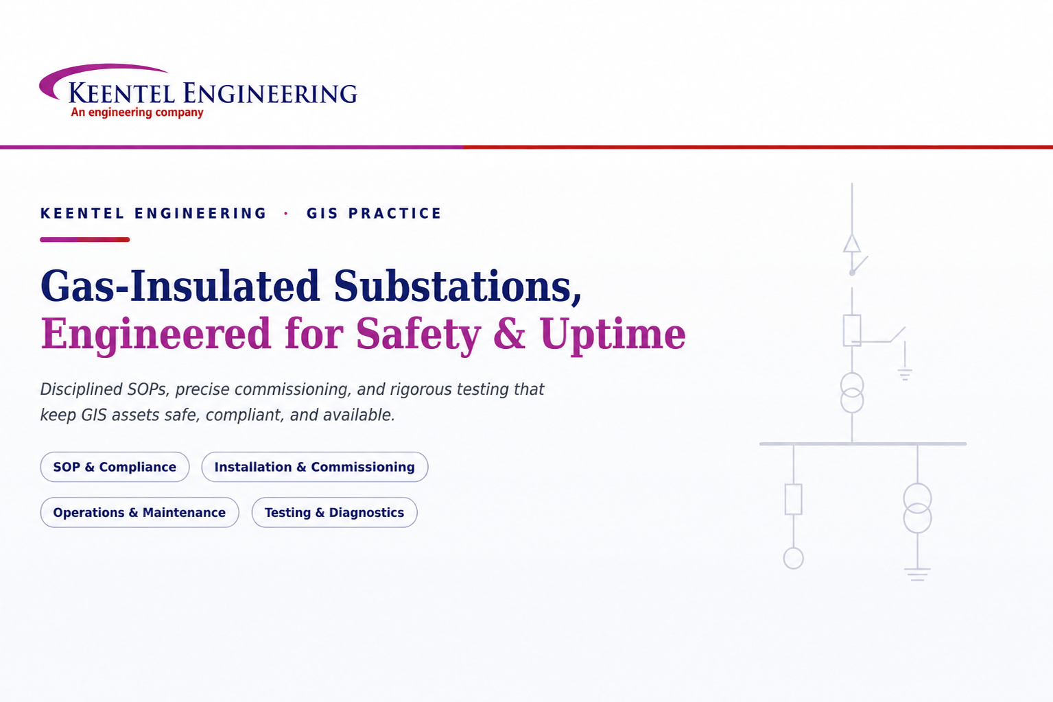
Learn GIS substation safety best practices, SOPs, commissioning, maintenance, interlocking, earthing, and testing to improve grid reliability and uptime.
By SANDIP R PATEL
•
July 23, 2026
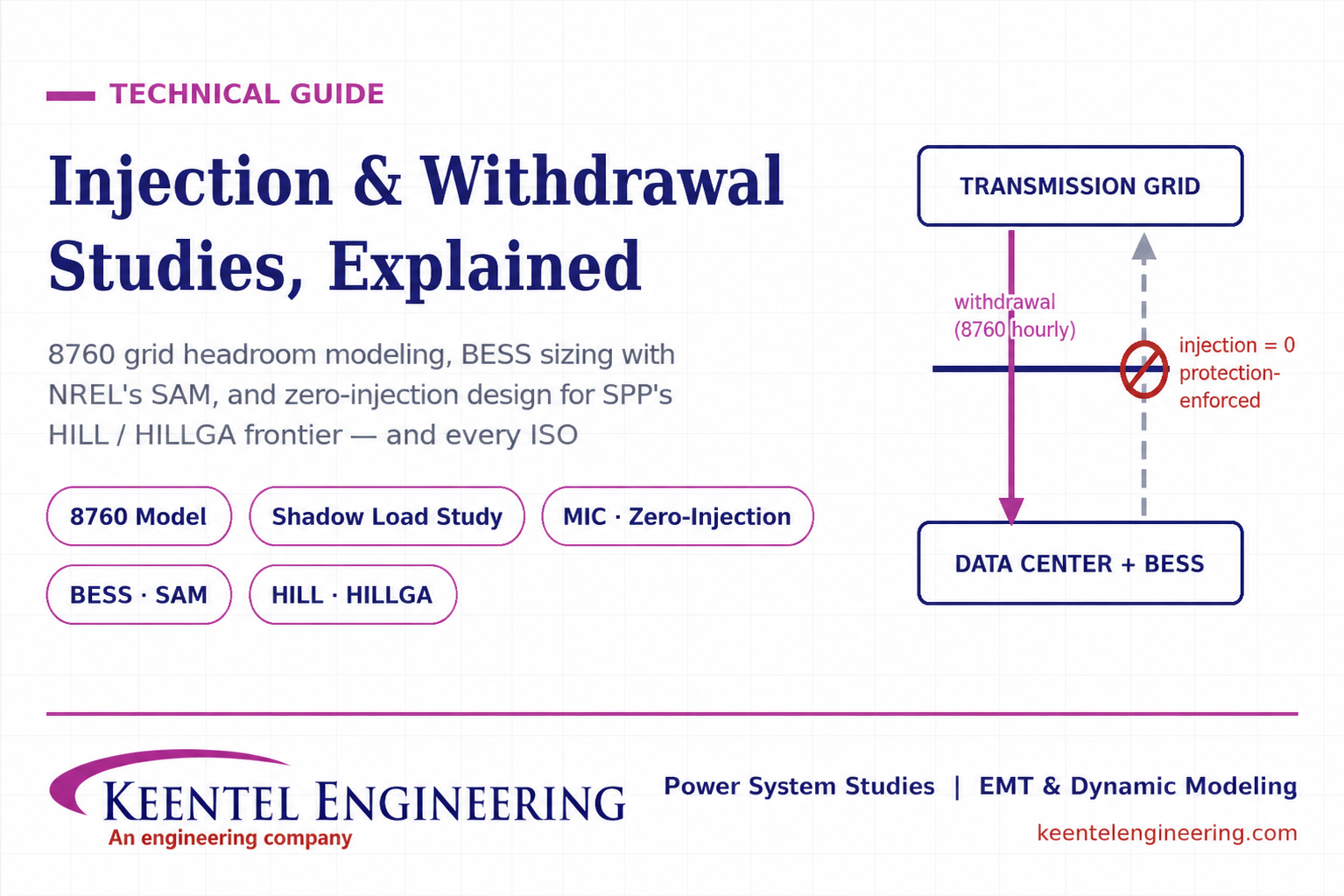
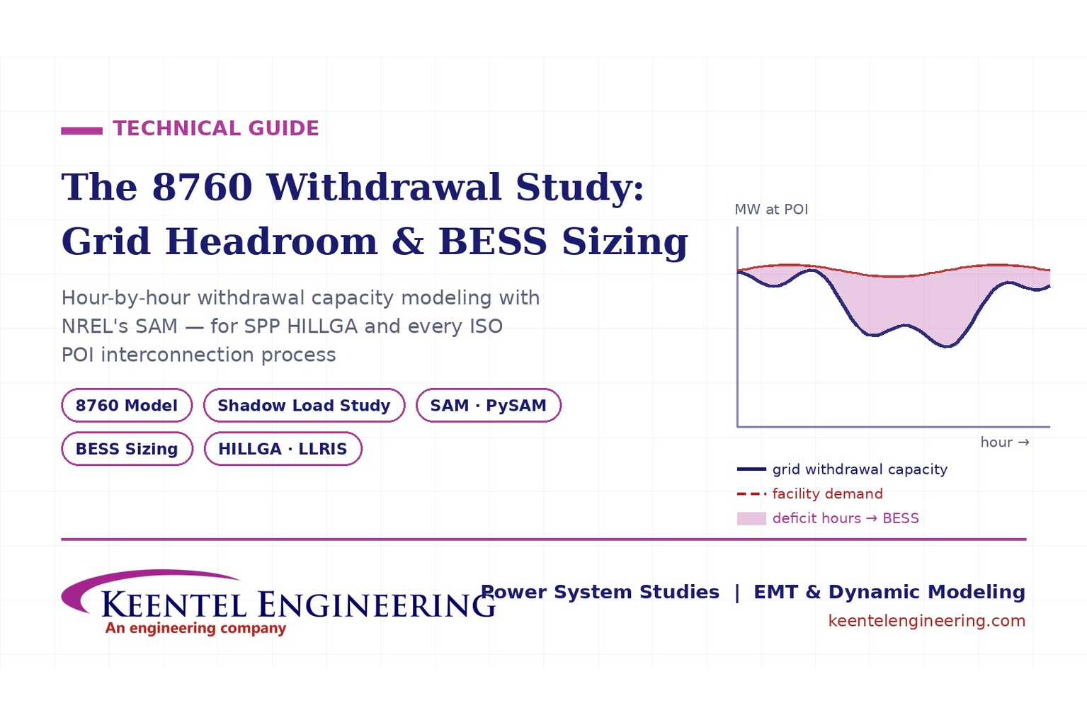
Learn how injection and withdrawal studies, 8760 headroom modeling, zero-injection engineering, and SPP HILLGA improve large load grid interconnections
By SANDIP R PATEL
•
July 21, 2026
Learn how an 8760 withdrawal study models hourly grid headroom and uses SAM-based BESS sizing for large-load interconnection projects.
By SANDIP R PATEL
•
July 21, 2026
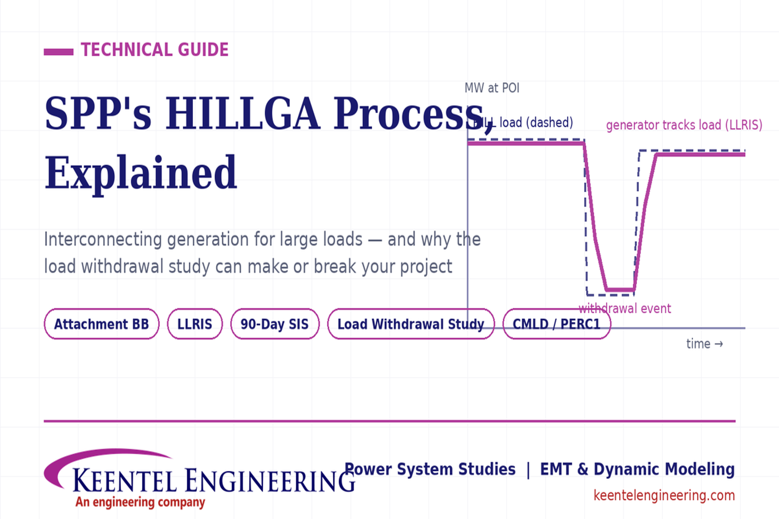
Learn how the SPP HILLGA process supports data center generation interconnection and why an 8760 withdrawal study can determine project success.
By SANDIP R PATEL
•
July 19, 2026
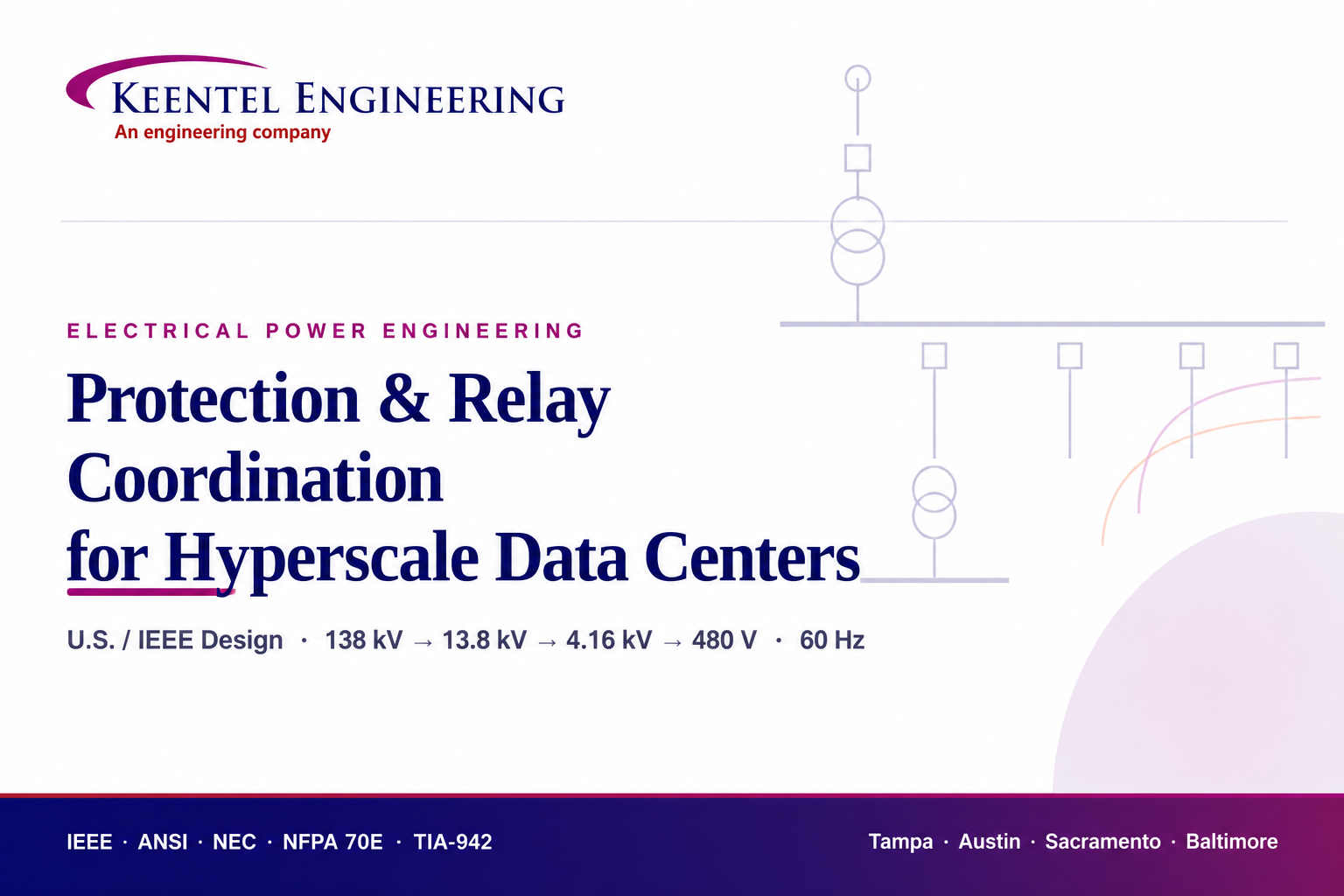
Learn electrical protection and relay coordination for hyperscale data centers with IEEE standards, short-circuit studies, arc-flash analysis, and MV protection.
By SANDIP R PATEL
•
July 18, 2026
Explore Battery Energy Storage System components, including cells, PCS, BMS, EMS, cooling, fire protection, sizing, safety, and grid codes.

By SANDIP R PATEL
•
July 18, 2026
Explore how grid-forming inverters support BESS, synthetic inertia, grid-code compliance, plant sizing, testing, and project revenue.
By SANDIP R PATEL
•
July 18, 2026
Learn how SEL RTAC protection monitoring supports NERC PRC-005 compliance, predictive maintenance alarms, automated reporting, and relay verification.
By SANDIP R PATEL
•
July 17, 2026
Explore utility-scale BESS design from the 10% package to IFC, NFPA 855 compliance, PSS®E/PSCAD models, and ERCOT interconnection.