
A Coordinated Electric System Interconnection Review—the utility’s deep-dive on technical and cost impacts of your project.
Challenge: Frequent false tripping using conventional electromechanical relays
Solution: SEL-487E integration with multi-terminal differential protection and dynamic inrush restraint
Result: 90% reduction in false trips, saving over $250,000 in downtime
ERCOT enforces all of the above through simulation, which means your model is your compliance case. The bar is now high:
- Whole-facility scope. The model must represent everything the IT load, the UPS and power conversion, the cooling plant, the protection and control systems in formats compatible with ERCOT's study platforms (PSS/E, PSCAD, TSAT).
- Real control loops, not approximations. Generic textbook representations are unacceptable. The model must capture the actual inner control behavior of your power electronics.
- Hardware-validated converter models. For electronic loads, the PSCAD model must be benchmarked against actual hardware testing including voltage ride-through and subsynchronous response. A model assembled from standard PSCAD library blocks fails by definition, because a generic block has never been tested against your vendor's hardware. The good news: validation is a hardware-type test, so results for a given converter product are reusable across every facility that uses it.
- Format migration. Facilities that previously submitted the older composite load model (CMLD) format must transition to EPRI's PERC1 format.
- Three checkpoints. Models are reviewed before the stability study begins (no model, no study), before each quarterly stability assessment, and for electronic loads one final time before energization, when you must submit as-built models with a documented comparison against the previously studied data and a sworn attestation that the model matches actual field settings. ERCOT's review takes 10 business days, extendable by 20 put it on your critical path.
- A living obligation. Change your technology, controls, or relay settings in a way that affects ride-through including converting a crypto mining site to an AI data center — and you've triggered a new interconnection study, even if your megawatts don't change.
| Parameter | Detail |
|---|---|
| System | 230 kV / 138 kV transmission corridors, wind and wet-snow icing exposure |
| Data basis | 15 years of minute-resolution forced-outage records + regional weather observations |
| Core methods | Event grouping, MVA performance curves, time-to-95%-restore, area outage rate curves, fragility modeling, rerun-history benefits, exceedance and log-domain risk metrics |
| Headline result | ≈85% of maximum resilience benefit at 60% of original capital; worst-event restoration window cut from 11 days to 5 in rerun-history terms |
| Decision supported | Capital portfolio selection; resilience plan filing; post-investment verification framework |
| System / Topic | Governing Standard(s) | What It Controls |
|---|---|---|
| Overall plant electrical distribution | IEEE 141 (Red Book); IEEE 666 | Distribution architecture, voltage selection, design of generating station auxiliary service systems |
| Power system studies | IEEE 399 (Brown Book); IEEE 551 | Load flow, symmetrical/asymmetrical short circuit, motor starting methodologies down to the lowest LV panelboard |
| Protection & coordination | IEEE 242 (Buff Book); IEEE 3004.5; IEEE C37 series | Generator relaying (21, 59N, 87G), time-current coordination, selective clearing between LV and MV tiers |
| GSU / UAT / SST transformers | IEEE C57.12.00 and C57 family | Transformer ratings, impedance, testing, loading |
| HV switchyard breakers | IEEE C37.06 | AC high-voltage circuit breaker preferred ratings |
| MV switchgear (13.8 kV) | IEEE C37.20.2; IEEE C37.20.7 | Metal-clad construction, compartmentalization, vacuum breakers; arc-resistant design with plenum venting |
| MV cable | UL 1072; ICEA S-93-639 (NEMA WC 74) | Type MV-105 shielded cable, 133% insulation level for HRG systems |
| LV switchgear (480 V) | IEEE C37.13; UL 1558 | Metal-enclosed LV power circuit breaker switchgear to 635 V, draw-out ACBs with electronic trip units |
| Motor control centers | UL 845; NEMA ICS 18 | LV-MCC construction, MCCB/MCP protection for motors under ~200 HP |
| Motors | NEMA MG-1 | Motor performance, starting characteristics, service factors |
| DC & battery systems | IEEE 485; IEEE 946 | Lead-acid battery sizing (125/250 VDC), DC auxiliary system design |
| Grounding | IEEE 80; IEEE 142 (Green Book) | Ground grid step/touch potential limits; system grounding including high-resistance grounding |
| Lightning protection | IEEE 998 | Direct-stroke shielding of switchyard and outdoor generator structures |
| Arc flash & electrical safety | IEEE 1584; NFPA 70E | Incident energy calculation; worker safety boundaries and PPE |
| Fire protection | NFPA 850 | Fire protection and risk management for combustion turbine generating plants |
| Installation code | NEC (NFPA 70); NESC | Wiring methods inside the plant fence; overhead/outdoor clearances at the switchyard |
| Interconnection & compliance | FERC LGIP; NERC MOD-025/026/027, PRC-019/024/029, FAC-008 | Interconnection process, model validation, protection/ride-through coordination, facility ratings |
| IFC / Construction Deliverable | Purpose |
|---|---|
| Stamped IFC packages | Legal basis for construction; P.E. responsible charge |
| Final relay settings & TCCs | Protection as-installed matches the coordination study |
| Calculation archive | Owner records; NERC audit evidence trail |
| Commissioning procedures | Safe, sequenced energization; MOD field testing |
| Construction support | RFIs, field changes, FAT/SAT witness |
| As-builts & model handoff | Operating baseline; future study currency |
| Metric | Outcome |
|---|---|
| Defects found pre-occupancy | Three topology defects and one settings-mismatch family corrected before load migration; the shared-switchboard defect alone would have invalidated the concurrently-maintainable claim on day one |
| IST findings | Fourteen additional discrepancies surfaced under scenario testing (control logic, alarm mapping, one generator sequencing fault) — all closed before handover instead of during operations |
| Black-building test | Passed on second execution; the first attempt exposed the generator sequencing fault under true block load, exactly the failure the compressed plan would never have found |
| Handover quality | Operations team certified on the actual failure scenarios; corrected EOPs and settings documentation delivered as controlled documents |
| Business outcome | Occupancy proceeded three weeks behind the original date — against an independent estimate that the uncorrected sequencing fault carried a high probability of a full facility outage within the first year |
Part 2 — Frequently Asked Questions: Large Load Interconnection
An electric grid must remain in continuous balance — generation onto the grid must equal consumption from it at every instant. PJM achieves this balance, and prices it, through a layered market architecture. Each layer operates on a different time horizon, and each one touches project economics differently.
| Domain | Key Standards / Codes | What They Govern |
|---|---|---|
| Fire safety | NFPA 855; UL 9540 / UL 9540A | Installation requirements, separation, gas management; system safety listing and thermal-runaway fire testing |
| Grid interconnection | IEEE 1547 (distribution); IEEE 2800 (transmission IBRs) | Ride-through, reactive capability, power quality, and performance at the point of interconnection |
| Power quality | IEEE 519 | Harmonic distortion limits at the PCC |
| Protection & grounding | IEEE 80 / 81 / 142; C37 series | Grounding system design and testing; protective relaying |
| Reliability compliance | NERC standards (incl. PRC ride-through requirements) | Registered-entity obligations for grid-connected storage |
Automating Protection System Monitoring and Verification With the SELRTAC
Jul 17, 2026 | Blog
A Practical Framework for Continuous NERC PRC-005 Compliance, Predictive Maintenance Alarming, and Automated Reporting
The Silent Sentinel Problem
Protection relays are unusual assets. Unlike a transformer that hums under load every hour of every day, a generator or transmission protection relay may sit armed for months — sometimes years — before it is ever called upon to operate. When that moment finally arrives, the relay must trip correctly, instantly, and in coordination with every other device in the scheme. There is no second chance. A failed CT circuit, a drifted setting, a degraded communications channel, or a quietly failing power supply can remain completely invisible until the exact moment the system needs the relay most, and the result is either a failure to operate or a false operation — both of which can cascade into equipment damage, extended outages, and NERC misoperation reporting.
This is the fundamental weakness of purely time-based maintenance: it verifies the protection system only at discrete points on the calendar. Everything that happens between test intervals is an act of faith. The industry answer to this problem — and the foundation of the performance-based options within NERC PRC-005 — is continuous, automated monitoring of protection system components using the self-test intelligence and communications capability already built into modern microprocessor relays and intelligent electronic devices (IEDs).
In this article, we walk through a practical, field-proven architecture for building that automated monitoring layer using the SEL Real-Time Automation Controller (RTAC) as the central data concentrator, logic engine, and reporting platform. We cover the six functional pillars of an automated protection monitoring program: settings and firmware verification, continuous CT/PT validation, protection channel integrity monitoring, IED hardware diagnostics, automated report generation, and durable maintenance-condition logging.
Keentel Insight
PRC-005 defines the protection system broadly: protective relays, associated communications systems,voltage- and current-sensing devices and their circuits, dc control circuitry, and station dc supplies. An automated monitoring program that only watches relay self-test bits covers a fraction of that scope.The architecture described here is designed to reach across the full definition — including the instrument transformer circuits and communications channels that manual programs routinely under-test.
Why Automate? Compliance Is the Floor, Not the Ceiling
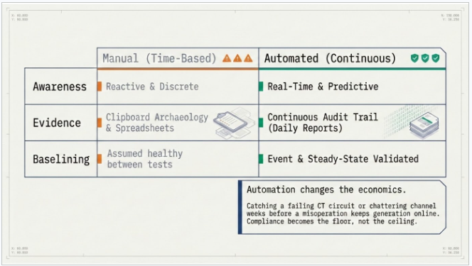
NERC, under FERC oversight, requires registered entities to maintain a documented protection system maintenance program with activities executed on time-based intervals, performance-based intervals, or a combination of the two. Meeting that obligation with clipboards and spreadsheets is possible — but it is slow, error-prone, and audit preparation becomes an archaeology project. Automation changes the economics entirely. When IEDs are continuously interrogated and every anomaly is timestamped and logged, three things happen at once:
- Awareness: Failed or degrading components that would otherwise go unnoticed between maintenance intervals are surfaced in near real time, dramatically improving protection system awareness.
- Documentation: Every monitored component generates a continuous evidentiary record that directly supports maintenance and validation testing documentation requirements — the daily report itself becomes audit evidence.
- Baselining: The behavior of power system components is captured during both fault events and steady-state operation, giving engineers baseline data that makes abnormal behavior obvious.
Beyond the compliance case, predictive alarming on critical assets is simply good asset management. Catching a failing CT circuit or a chattering communications channel weeks before it causes a misoperation keeps generation online, protects capital equipment, and avoids the reputational and regulatory cost of a reportable event.
The RTAC as the Monitoring Backbone
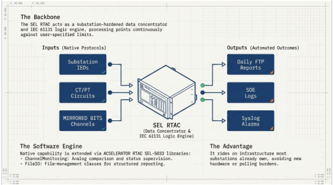
The SEL RTAC is a substation-hardened data concentrator and communications gateway with an integrated IEC 61131 programming environment. That combination is exactly what an automated monitoring program needs: the RTAC already speaks to every IED in the station over its native protocols, it already polls measurements and status points on user-defined intervals, and its logic engine can process those points continuously against user-specified limits. In other words, the monitoring system rides on infrastructure most substations already own.
SEL extends the RTAC's native capability with the ACSELERATOR RTAC SEL-5033 library extensions — downloadable libraries that plug into the IEC 61131-3 environment. Two libraries do the heavy lifting for protection monitoring: the ChannelMonitoring library, which provides purpose-built function blocks for comparing analog channels and supervising status indicators, and the FileIO library (a paid option requiring the correct model option table), which provides file-management classes for writing structured reports to the RTAC file system. Each library installs with its own instruction manual, accessible directly from the RTAC help menu.
Programs can be written in Continuous Function Chart (CFC) for engineers who prefer graphical logic, or in Structured Text (ST) for those who prefer code. The function blocks output Boolean alerts alongside enumerated status values, and helper functions convert those enumerations to human-readable strings for logging — a small detail that pays off enormously when reports are reviewed months later.
Pillar 1: Verifying Commissioned Settings and Firmware.
The first question any protection monitoring program must answer is deceptively simple: is the relay still configured the way we commissioned it? Settings drift is real — a technician's temporary change that never got reverted, a firmware update that altered default behavior, an unauthorized modification. Under a manual program, these discrepancies hide until the next scheduled settings review.
The Configuration Monitor feature in SEL clients solves this elegantly. The RTAC periodically sends ASCII commands to each SEL IED — by default, commands that retrieve the relay ID information and the settings configuration — and computes a 32-bit cyclic redundancy check (CRC) over each valid response. That CRC is stored as the baseline. On every subsequent poll, the freshly computed CRC is compared against the stored value. A mismatch pulses a dedicated mismatch pin in the logic, flagging that something in the relay's configuration has changed; a response that cannot be validated pulses a separate error pin.
Engineers can tune the monitoring interval, retry behavior, and access level, and can add additional ASCII commands to widen the verification scope — subject to confirming command support in the specific relay firmware.
Two practical field notes: the Configuration Monitor ships disabled and must be explicitly enabled in the logic pin settings, and software flow control on serial channels can interfere with the monitor — disabling Xon/Xoff flow control in the communications settings resolves it. These are exactly the kinds of details that separate a monitoring system that works in the lab from one that works in the field.
Keentel Insight
Treat the settings CRC baseline as a controlled configuration item. When an authorized settings change is made, re-baseline deliberately and record the event in your change-management log. A mismatch alarm should always mean one of two things: an undocumented change (a compliance finding waiting to happen) or a relay malfunction. Either way, it deserves immediate investigation.
Pillar 2: Continuous CT and PT Verification
Instrument transformer circuits are among the hardest protection system components to verify. A shorted CT winding, a corroded terminal block, an open test switch, a failing analog-to-digital converter — any of these can silently corrupt the current or voltage picture the relay depends on. Traditional verification requires an outage and a test set.
The ChannelMonitoring library provides two function blocks purpose-built for this task. Both alert on test failure — meaning either a sustained divergence between compared inputs or repeated short divergences (chatter) — and both track the quality of the input data itself, so a communications dropout is distinguishable from a genuine measurement problem.
Cross-Comparison Within One IED
Where a relay has two current terminals wired to independent CTs — the classic example being the high side and load side of a breaker — the multi-channel alert function block compares the phase measurements from the two CT sets against each other. Under normal through-current conditions, the two measurement sets should agree closely. A sustained excursion beyond a user-defined threshold, held for a user-defined time, indicates a developing problem in one of the CT circuits or the relay's measuring chain. Monitoring is typically supervised so it only runs when there is enough signal to compare meaningfully — for example, enabling comparison only when measured power exceeds five percent of nominal, which prevents nuisance alarms at light load.
Cross-Comparison Across Multiple IEDs
The single-channel alert function block generalizes the idea across the substation: a common phase measurement is gathered from several IEDs whose CTs see related current, and each is compared against a chosen reference IED. Because the comparison exercises the entire measurement chain CT, secondary wiring, relay input, and analog-to-digital conversion a persistent deviation on one device localizes the problem quickly. Supervising the comparison with the reference measurement's quality flag ensures the scheme only evaluates when the reference data is valid.
One implementation detail worth understanding: SEL protocol returns many analog values as complex measured values carrying both magnitude and angle, while the comparison blocks consume simple measured values. A small conversion function that maps the magnitude, quality, and timestamp fields bridges the two data types a few lines of Structured Text that get reused across every monitoring program in the fleet.
Pillar 3: Protection Channel Integrity
Communications-assisted protection schemes — permissive transfer trip, direct transfer trip, line current differential — are only as reliable as the channel underneath them. A channel that drops messages intermittently may still pass a monthly loopback test while degrading the security and dependability of the scheme every day in between. Continuous channel supervision closes that gap and provides early warning of conditions that could culminate in a misoperation.
For serial MIRRORED BITS channels, the RTAC's built-in communications diagnostics expose an instantaneous receive-health indicator that deasserts the moment any of several transmission error types is detected, or whenever an expected message fails to arrive within the time needed to transmit three messages. Supervising that indicator with an indicator-alert function block — inverted, since the block detects assertion while the failure condition is a deassertion — yields a channel monitor that distinguishes between an occasional hiccup and a genuinely sick channel. The block's chatter counting catches channels that fail repeatedly for short periods, while its excursion timing catches sustained outages. Tying the monitor's enable to the communications instance's own enable status prevents false alarms when the channel is intentionally out of service.
Pillar 4: IED Hardware Diagnostics
Every SEL IED continuously self-tests its major internal components — power supplies, memory, analog measurement circuitry, and more. When a self-test finds a parameter out of tolerance but not yet compromising protection, the relay raises a warning alarm and pulses a contact. When the condition is severe, the relay declares a failure, and critically, enters a protection-disabled state. A relay sitting in failure is a protection hole in the system, and the clock on finding it should be measured in minutes, not maintenance cycles.
The hardware alarm Relay Word bit consolidates this self-test status into a single monitorable point. Polling that bit from the RTAC and supervising it with an indicator-alert function block — enabled only while the IED is online and responding to polls, so an offline device does not masquerade as a hardware failure — provides continuous assurance that every relay in the station is healthy. The chatter capability adds nuance: repeated warnings over a window indicate a developing out-of-tolerance condition worth scheduling maintenance for, while a sustained assertion demands immediate response. Many SEL IEDs expose additional configurable alert points beyond the consolidated hardware alarm, and the same supervision pattern extends to them directly.
Pillar 5: Automated Daily Reporting
Monitoring without reporting is just data. The reporting layer is what converts continuous monitoring into compliance evidence and actionable maintenance intelligence. Using the FileIO library's log directory manager class, the RTAC can generate a structured maintenance report on a user-defined interval daily being the natural cadence and manage the report archive automatically with configurable folder size limits, file counts, and naming conventions.
The report logic follows four simple steps: track the time elapsed since the last report, convert each function block's outputs into human-readable strings using the library's enumeration-to-string helpers, assemble formatted message blocks for every monitored component, and trigger the write. The resulting daily report consolidates in one document the status of relay configurations, instrument transformer circuits and their associated
measuring chains, protection communications channels, and relay hardware alarms. Reports are downloadable on demand through the RTAC's web interface or pushed automatically to a centralized server over FTP, which is how fleet-scale programs aggregate station-level reports into an enterprise compliance archive.
Pillar 6: Durable Maintenance-Condition Logging
Reports summarize; logs prove. Every detected maintenance condition should also land in the RTAC's Sequence of Events (SOE) record, which provides nonvolatile storage for up to 30,000 log items. SOE data is accessible through the web interface or an ODBC connection, and can be streamed via Syslog protocol to a central syslog server for long-term archiving. For organizations not ready to purchase the FileIO library, SOE-plus-Syslog is a capable standalone mechanism for preserving maintenance alert history — and for organizations running the full reporting stack, it is the redundant evidentiary layer that makes the audit trail bulletproof.
Putting It Together: Program Design Considerations
The function blocks are the easy part. In our experience, the difference between a monitoring program that earns its keep and one that generates alarm fatigue comes down to engineering judgment in five areas:
Threshold engineering
Excursion thresholds and time delays must reflect the actual measurement uncertainty of each comparison — CT accuracy class, relay metering accuracy, and normal load asymmetry all belong in the threshold calculation.
Supervision logic
Every monitor needs an enable condition that answers the question: under what system conditions is this comparison meaningful? Light-load cutoffs, quality supervision, and offline supervision eliminate the majority of nuisance alarms.
Tag architecture
Alert outputs, statuses, and quality indicators should be mapped to a consistent tag structure across every station in the fleet, so reports read identically everywhere and enterprise aggregation is trivial.
Change management
The monitoring system itself is a change-controlled asset. Settings baselines, threshold revisions, and logic versions belong under the same configuration management discipline as relay settings.
Operational ownership. Reports only create value if someone owns the review. Define who reads the daily report, what constitutes an actionable finding, and how findings feed the maintenance work order system.
Keentel Insight
Start with the monitors that protect against your highest-consequence failure modes: hardware alarms on every relay, channel monitoring on every communications-assisted scheme, and configuration monitoring fleet-wide. CT/PT cross-comparison delivers enormous value but requires the most careful threshold engineering phase it in once the foundational monitors are stable and trusted.
How Keentel Engineering Helps
Keentel Engineering designs, programs, commissions, and documents automated protection system monitoring programs end to end — from PRC-005 program architecture and monitoring scope definition, through RTAC logic development in CFC and Structured Text, threshold and supervision engineering, report and SOE archiving design, and integration with enterprise compliance documentation systems. Our team combines licensed professional engineering oversight with hands-on RTAC, relay, and communications expertise across generation, transmission, and utility-scale renewable facilities. Whether you are building a monitoring program from scratch, expanding coverage under a performance-based maintenance strategy, or preparing for an audit, we deliver systems that are defensible, maintainable, and genuinely useful to your operations team.
Conclusion
Protection relays are silent sentinels — and silence is precisely the problem. A relay that has not operated in years tells you nothing about whether it will operate correctly tomorrow. By pairing the RTAC's data concentration and IEC 61131 logic capabilities with purpose-built monitoring libraries, engineers can continuously verify relay configurations, instrument transformer circuits, protection communications channels, and relay hardware health; document every status in automated daily reports; and preserve every maintenance condition in durable, archivable logs. The result is a protection system that reports on its own readiness every single day — turning compliance from a periodic scramble into a continuous byproduct of good engineering.
Case Study 1: Automated PRC-005 Monitoring for a Multi-Unit Generating Facility
All client, project, and location identifiers have been withheld to protect confidentiality.
Background
A generation owner operating a multi-unit facility connected to the bulk electric system maintained its protection system under a traditional time-based PRC-005 program. The facility's protection fleet included several dozen microprocessor relays covering generator, transformer, and interconnection protection, with an existing RTAC serving as the station data concentrator and SCADA gateway. Maintenance verification was performed manually at scheduled intervals, and compliance documentation was assembled from technician test records spread across multiple systems.
Challenge
Two events drove the owner to seek a better approach. First, an internal review discovered that a relay settings change made during a troubleshooting session had never been reverted or documented — the discrepancy had persisted undetected for months and was found only by chance during an unrelated review. Second, audit preparation for the compliance program consumed weeks of engineering time reconstructing evidence from disparate records. The owner needed continuous assurance that relay configurations matched the commissioned baseline, early warning of instrument transformer and measuring-chain problems on critical breakers, and audit-ready documentation generated automatically rather than assembled retroactively.
Keentel's Solution
Keentel Engineering designed and implemented an automated protection monitoring program on the facility's existing RTAC, structured around four monitoring layers:
- Settings and firmware verification. Configuration monitoring was enabled across the SEL relay fleet, with the RTAC periodically retrieving relay identification and settings information, computing CRC baselines, and alarming on any mismatch or invalid response. Command sets were verified against each relay's firmware documentation, and serial flow-control conflicts identified during testing were resolved.
- Dual-CT cross-comparison. On critical breakers where relays measured independent CT sets on the high and load sides, multi-channel comparison logic was deployed to continuously cross-check phase measurements. Comparison was supervised to enable only above a minimum loading threshold, with excursion thresholds engineered from CT accuracy class and relay metering tolerance.
- Fleet measurement validation. Phase measurements from multiple relays across the station were compared against a designated reference device, supervised by reference data quality, to validate CT circuits and relay analog-to-digital conversion chains without outages.
- Automated reporting and logging. A daily maintenance report was implemented using the RTAC's file-management library, consolidating the monitoring-enabled state, alert state, status, and data quality of every monitored component into a single archived document, with automated transfer to the owner's central compliance server and parallel logging of all maintenance conditions to the Sequence of Events record.
All logic was delivered in documented Continuous Function Chart programs with a standardized virtual tag architecture, factory-tested against simulated deviation scenarios, and commissioned with the owner's protection staff. The engineering package was sealed under professional engineering oversight and included a monitoring program basis document mapping each monitor to the corresponding maintenance program element.
Results
| Outcome Area | Result Delivered |
|---|---|
| Configuration assurance | Every relay configuration now verified continuously against commissioned baseline; undocumented changes alarm within one monitoring cycle |
| Early fault detection | A developing measurement divergence on one breaker CT circuit was flagged by the comparison logic and corrected during a planned outage — before any protection impact |
| Audit preparation | Compliance evidence assembly reduced from weeks of reconstruction to retrieval of automatically generated daily reports |
| Alarm quality | Supervision and threshold engineering held nuisance alarms to near zero after the tuning period |
| Operational adoption | Daily report review integrated into the plant's morning operations meeting with defined escalation paths |
Why It Matters
The settings discrepancy that once hid for months would now surface in a single monitoring cycle. Continuous verification converted the owner’s compliance posture from periodic reconstruction to standing evidence and caught a real CT circuit problem before it could affect protection performance.
Case Study 2: Protection Channel and Relay Health Monitoring for a Transmission Owner
All client, project, and location identifiers have been withheld to protect confidentiality.
Background
A transmission owner operated multiple high-voltage substations employing communications-assisted protection schemes over serial MIRRORED BITS channels between line terminals. The owner's protection group had experienced an intermittent channel problem that degraded a pilot scheme for an extended period before being identified — the channel passed its periodic tests, but message errors were occurring between test intervals. Separately, the owner had no continuous visibility into relay hardware self-test status across its fleet; a relay entering a protection-disabled failure state would be discovered only through SCADA alarm review or a site visit.
Challenge
The owner required continuous, quantitative visibility into protection channel health at every terminal, immediate awareness of any relay hardware warning or failure condition fleet-wide, and a durable, centralized record of every maintenance condition suitable for both engineering trend analysis and compliance evidence — all deployable across multiple stations with consistent behavior and without adding hardware.
Keentel's Solution
Keentel Engineering developed a templated monitoring package deployed to the RTAC at each station:
Channel integrity monitoring
For every MIRRORED BITS instance, logic supervises the built-in instantaneous receive-health diagnostic — which deasserts on any detected transmission error or on failure to receive a message within the time required to transmit three messages. Indicator-alert supervision with chatter counting distinguishes intermittently degraded channels from sustained outages, and each monitor's enable is tied to the communications instance's own enabled status to suppress alarms during intentional channel outages.
Fleet hardware health monitoring
The consolidated hardware alarm bit on every SEL relay is polled continuously and supervised by indicator-alert logic enabled only while the device is online and responding — ensuring an offline device is reported as a communications condition, not misreported as a hardware failure. Chatter detection surfaces repeated warnings indicative of developing out-of-tolerance conditions; sustained assertion escalates immediately.
Centralized condition logging
Every detected maintenance condition is written to the RTAC Sequence of Events record — nonvolatile storage supporting up to 30,000 entries per device — and streamed via Syslog protocol to the owner's central log server, creating a fleet-wide, timestamped maintenance history without requiring additional report licensing at every station. Stations with file-management licensing additionally generate consolidated daily reports transferred by FTP to the compliance archive.
The package was engineered once, documented as a deployment standard with a fixed tag architecture and setting philosophy, and rolled out station by station — each deployment consisting primarily of configuration and site acceptance testing rather than new logic development.
Results
| Outcome Area | Result Delivered |
|---|---|
| Channel visibility | Chatter-based supervision identified a degrading pilot channel exhibiting intermittent message errors; the channel was repaired before any scheme misoperation occurred |
| Hardware assurance | A relay hardware warning trend was detected and the device was proactively replaced during a scheduled outage, avoiding an unplanned protection-disabled condition |
| Fleet consistency | Identical monitoring behavior, tags, and reporting at every station, enabling meaningful cross-station trend analysis |
| Evidence quality | Centralized syslog archive provides timestamped, tamper-resistant maintenance history supporting both engineering analysis and compliance review |
| Deployment efficiency | Templated design reduced per-station engineering effort substantially after the first installation |
Why It Matters
The intermittent channel problem that once evaded periodic testing was exactly the failure mode continuous chatter supervision is built to catch. Fleet-wide hardware monitoring turned relay failure discovery from a matter of luck into a matter of minutes closing protection holes before the power system could find them first.
About Keentel Engineering
Keentel Engineering LLC is a power systems and grid interconnection consulting firm headquartered in Tampa, Florida, with offices in Austin, Sacramento, and Baltimore. Our services span point-of-interconnection and grid interconnection engineering, power system studies across EHV, HV, and MV networks, substation and transmission design, EMT modeling, utility-scale renewable and battery energy storage engineering, NERC compliance, owner's engineer services, and MEP engineering. Deliverables are produced under licensed professional engineering oversight (FL Firm Reg. No. 36853).
Frequently Asked Questions
Common questions we receive from asset owners, plant engineers, and compliance managers about automated protection system monitoring with the SEL RTAC.
Q. What does NERC PRC-005 actually require me to maintain?
PRC-005 requires a documented protection system maintenance program covering protective relays, associated communications systems, voltage- and current-sensing devices and their circuits, dc control circuitry, and station dc supplies associated with protection functions. Maintenance activities must be executed on time-based intervals, performance-based intervals, or a combination of both — and every activity must be documented.
Q. How does automated monitoring fit into a PRC-005 program?
Modern IEDs continuously self-test and communicate. By concentrating that data in an RTAC and processing it against defined limits, many components can be verified continuously rather than only at periodic test intervals. Continuous monitoring improves protection system awareness, supports the documentation requirements for monitored components, and captures component behavior during both faults and steady-state operation — while also enabling predictive maintenance well beyond the compliance minimum.
Q. Why use the RTAC as the monitoring platform instead of a SCADA historian or separate monitoring appliance?
The RTAC is already the substation data concentrator and communications gateway in many stations — it already polls every IED over native protocols. Its integrated IEC 61131 programming environment means the monitoring logic runs at the substation edge, deterministically, with direct access to communications diagnostics that upstream systems never see. No additional hardware, no additional polling burden on the relays.
Q. What is the Configuration Monitor and how does it detect settings changes?
The Configuration Monitor periodically sends ASCII commands to each SEL IED — by default retrieving relay ID and settings information — and computes a 32-bit CRC over each valid response. The CRC is compared against the stored baseline on every cycle. A mismatch pulses a dedicated alert pin, indicating the configuration changed; an invalid response pulses a separate error pin. Intervals, retries, access levels, and the command list are all user-configurable.
Q. Does the Configuration Monitor work out of the box?
Almost — three field notes matter. It ships disabled and must be explicitly enabled in the logic pin settings. The default commands should be verified against the relay's manual for firmware support. And software flow control on serial channels can interfere with it, so Xon/Xoff should be disabled in the communications settings when the issue appears.
Q. Can I really verify CTs and PTs without taking an outage?
For many failure modes, yes. Continuous cross-comparison of live measurements — between two CT sets on one relay, or between multiple IEDs measuring related quantities against a reference — detects sustained or repeated divergences that indicate developing problems in the CT/PT circuits, secondary wiring, or the relay's analog measuring chain. It complements, rather than replaces, commissioning-grade testing, but it dramatically shortens the time a silent circuit failure can persist undetected.
Q. What are the ChannelMonitoring and FileIO libraries?
They are ACSELERATOR RTAC SEL-5033 library extensions. ChannelMonitoring provides the comparison and supervision function blocks — multi-channel analog comparison, single-channel comparison against a reference, and Boolean indicator supervision — along with helper functions that convert enumerated statuses into readable strings. FileIO provides file-management classes used to write and manage structured report files; it is a paid option and requires the correct model option table on the RTAC.
Q. What is the difference between an alert, a status, and a quality alert on these function blocks?
The alert is the Boolean output indicating a test failure — a sustained divergence or repeated divergences (chatter). The status output is an enumerated value describing the block's current state, convertible to a readable string for reporting. The quality alert indicates a problem with the input data itself, so a communications dropout or bad-quality measurement is distinguishable from a genuine component deviation.
Q. How do I monitor a MIRRORED BITS protection channel?
The RTAC's built-in communications diagnostics include an instantaneous receive-health indicator for every MIRRORED BITS instance. It deasserts the moment any transmission error type is detected, or when a message is not received in the time required to transmit three messages. Supervising the inverse of that indicator with an indicator-alert function block — with chatter counting for intermittent trouble and excursion timing for sustained outages — provides continuous channel health monitoring.
Q. What happens when a relay hardware self-test fails?
When a self-test finds one or more internal components out of tolerance but not compromising protection, the relay generates a warning alarm and pulses a contact. For a severe out-of-tolerance condition, it issues a failure alarm and enters a protection-disabled state — meaning the protected element is exposed until the relay is replaced or repaired. Continuously monitoring the consolidated hardware alarm bit ensures a protection-disabled relay is found in minutes, not at the next scheduled maintenance visit.
Q. What ends up in the automated daily report?
One consolidated document covering the status of every monitored component: relay configuration verification, IED and CT/PT measurement comparisons and associated circuitry, protection communications channels, and relay hardware alarms — each with monitoring-enabled state, alert state, status, and data quality rendered as readable text. Reports are retrievable through the RTAC web interface or pushed automatically to a centralized server via FTP.
Q. Can I keep maintenance history without buying the FileIO library?
Yes. Detected maintenance conditions can be logged to the RTAC's Sequence of Events record, which provides nonvolatile storage for up to 30,000 items. SOE data is accessible via the web interface or ODBC and can be streamed over Syslog protocol to a central server for archiving — a capable evidentiary mechanism on its own, and a valuable redundant layer alongside file-based reporting.

About the Author:
Sandip "Sonny" R. Patel, P.E.
IEEE Senior Member · Founder & CEO, Keentel Engineering
In 1995, Sonny Patel earned his Electrical Engineering degree from the University of Illinois. But degrees don't build legacies — action does.
For three decades, he has worked the power industry from every side of the table: 16 years as a utility engineer at Exelon/Commonwealth Edison; generation leadership across hydroelectric, industrial steam turbine, and a 9 GW renewable fleet; NERC Regional Entity Senior Compliance Engineer and Audit Team Lead, auditing some of the nation's largest utilities; and testing and commissioning lead on equipment up to 765 kV — the very top of the North American grid.Utility. Generator. Regulator. Consultant. Few engineers have seen all four seats. Fewer still have sat in them.
His experience spans nuclear, hydro, conventional generation, renewables, oil and gas, mining — and today's data centers, where he is authoring a three-book series on data center design. He is a Licensed Professional Engineer in six states and a Licensed Electrical Contractor in Florida (Unlimited EC) — he doesn't just design the work; he's qualified to stand behind its execution.Today, as Founder and CEO of Keentel Engineering, Sonny leads a nationwide team of engineers delivering substation design, power system studies, NERC compliance, and commissioning — done right, coast to coast.Three decades. Every side of the table. One standard: accountable engineering.
Services

Let's Discuss Your Project
Let's book a call to discuss your electrical engineering project that we can help you with.
About the Author:
Sandip "Sonny" R. Patel, P.E.
IEEE Senior Member · Founder & CEO, Keentel Engineering
In 1995, Sonny Patel earned his Electrical Engineering degree from the University of Illinois. But degrees don't build legacies — action does.
For three decades, he has worked the power industry from every side of the table: 16 years as a utility engineer at Exelon/Commonwealth Edison; generation leadership across hydroelectric, industrial steam turbine, and a 9 GW renewable fleet; NERC Regional Entity Senior Compliance Engineer and Audit Team Lead, auditing some of the nation's largest utilities; and testing and commissioning lead on equipment up to 765 kV — the very top of the North American grid.
Utility. Generator. Regulator. Consultant. Few engineers have seen all four seats. Fewer still have sat in them.
His experience spans nuclear, hydro, conventional generation, renewables, oil and gas, mining — and today's data centers, where he is authoring a three-book series on data center design. He is a Licensed Professional Engineer in six states and a Licensed Electrical Contractor in Florida (Unlimited EC) — he doesn't just design the work; he's qualified to stand behind its execution.
Today, as Founder and CEO of Keentel Engineering, Sonny leads a nationwide team of engineers delivering substation design, power system studies, NERC compliance, and commissioning — done right, coast to coast.Three decades. Every side of the table. One standard: accountable engineering.
Leave a Comment
Thank you for contacting us.
We will get back to you as soon as possible.
We will get back to you as soon as possible.
Oops, there was an error sending your message.
Please try again later.
Please try again later.
Related Posts

By Team 2 Dexora
•
October 20, 2026
Explore grounding system testing with Keentel Engineering. Learn IEEE 80/81 methods, soil resistivity, ground resistance, and touch and step voltage safety.

By SANDIP R PATEL
•
October 13, 2026
Plan data center capacity with land screening, MW-per-acre estimates, grid power availability and interconnection feasibility studies from Keentel Engineering.

By SANDIP R PATEL
•
October 11, 2026
Learn which fault produces the highest current at a bus, why SLG faults can exceed three-phase faults, and how symmetrical components determine fault duty.

By SANDIP R PATEL
•
October 11, 2026
Learn why zero-sequence current pulsates in the dq0 frame, how Park's transformation works, and how inverter controls handle unbalance and ground faults.

By SANDIP R PATEL
•
October 11, 2026
Explore grid inertia, RoCoF and frequency response, with swing equation calculations, frequency nadir analysis and US power system simulation examples.

By SANDIP R PATEL
•
October 11, 2026
Learn transient stability analysis, swing equation, equal-area criterion and critical clearing time with a 345 kV worked example and NERC TPL-001 guidance.

By SANDIP R PATEL
•
October 11, 2026
Learn why inverter controls become unstable in weak grids, how PLL bandwidth and SCR affect stability, and how PSCAD EMT studies identify and mitigate oscillations.

By SANDIP R PATEL
•
October 11, 2026
Learn how STATCOMs improve voltage stability and prevent FIDVR. Explore reactive power sizing, delayed fault clearing, NERC criteria and 138 kV simulation results.

By SANDIP R PATEL
•
October 10, 2026
Learn BESS DC sizing with power, energy, current and C-rate calculations, battery losses, degradation and a 100 MW/400 MWh utility-scale example.





