
A Coordinated Electric System Interconnection Review—the utility’s deep-dive on technical and cost impacts of your project.
Challenge: Frequent false tripping using conventional electromechanical relays
Solution: SEL-487E integration with multi-terminal differential protection and dynamic inrush restraint
Result: 90% reduction in false trips, saving over $250,000 in downtime
ERCOT enforces all of the above through simulation, which means your model is your compliance case. The bar is now high:
- Whole-facility scope. The model must represent everything the IT load, the UPS and power conversion, the cooling plant, the protection and control systems in formats compatible with ERCOT's study platforms (PSS/E, PSCAD, TSAT).
- Real control loops, not approximations. Generic textbook representations are unacceptable. The model must capture the actual inner control behavior of your power electronics.
- Hardware-validated converter models. For electronic loads, the PSCAD model must be benchmarked against actual hardware testing including voltage ride-through and subsynchronous response. A model assembled from standard PSCAD library blocks fails by definition, because a generic block has never been tested against your vendor's hardware. The good news: validation is a hardware-type test, so results for a given converter product are reusable across every facility that uses it.
- Format migration. Facilities that previously submitted the older composite load model (CMLD) format must transition to EPRI's PERC1 format.
- Three checkpoints. Models are reviewed before the stability study begins (no model, no study), before each quarterly stability assessment, and for electronic loads one final time before energization, when you must submit as-built models with a documented comparison against the previously studied data and a sworn attestation that the model matches actual field settings. ERCOT's review takes 10 business days, extendable by 20 put it on your critical path.
- A living obligation. Change your technology, controls, or relay settings in a way that affects ride-through including converting a crypto mining site to an AI data center — and you've triggered a new interconnection study, even if your megawatts don't change.
| Parameter | Detail |
|---|---|
| System | 230 kV / 138 kV transmission corridors, wind and wet-snow icing exposure |
| Data basis | 15 years of minute-resolution forced-outage records + regional weather observations |
| Core methods | Event grouping, MVA performance curves, time-to-95%-restore, area outage rate curves, fragility modeling, rerun-history benefits, exceedance and log-domain risk metrics |
| Headline result | ≈85% of maximum resilience benefit at 60% of original capital; worst-event restoration window cut from 11 days to 5 in rerun-history terms |
| Decision supported | Capital portfolio selection; resilience plan filing; post-investment verification framework |
| System / Topic | Governing Standard(s) | What It Controls |
|---|---|---|
| Overall plant electrical distribution | IEEE 141 (Red Book); IEEE 666 | Distribution architecture, voltage selection, design of generating station auxiliary service systems |
| Power system studies | IEEE 399 (Brown Book); IEEE 551 | Load flow, symmetrical/asymmetrical short circuit, motor starting methodologies down to the lowest LV panelboard |
| Protection & coordination | IEEE 242 (Buff Book); IEEE 3004.5; IEEE C37 series | Generator relaying (21, 59N, 87G), time-current coordination, selective clearing between LV and MV tiers |
| GSU / UAT / SST transformers | IEEE C57.12.00 and C57 family | Transformer ratings, impedance, testing, loading |
| HV switchyard breakers | IEEE C37.06 | AC high-voltage circuit breaker preferred ratings |
| MV switchgear (13.8 kV) | IEEE C37.20.2; IEEE C37.20.7 | Metal-clad construction, compartmentalization, vacuum breakers; arc-resistant design with plenum venting |
| MV cable | UL 1072; ICEA S-93-639 (NEMA WC 74) | Type MV-105 shielded cable, 133% insulation level for HRG systems |
| LV switchgear (480 V) | IEEE C37.13; UL 1558 | Metal-enclosed LV power circuit breaker switchgear to 635 V, draw-out ACBs with electronic trip units |
| Motor control centers | UL 845; NEMA ICS 18 | LV-MCC construction, MCCB/MCP protection for motors under ~200 HP |
| Motors | NEMA MG-1 | Motor performance, starting characteristics, service factors |
| DC & battery systems | IEEE 485; IEEE 946 | Lead-acid battery sizing (125/250 VDC), DC auxiliary system design |
| Grounding | IEEE 80; IEEE 142 (Green Book) | Ground grid step/touch potential limits; system grounding including high-resistance grounding |
| Lightning protection | IEEE 998 | Direct-stroke shielding of switchyard and outdoor generator structures |
| Arc flash & electrical safety | IEEE 1584; NFPA 70E | Incident energy calculation; worker safety boundaries and PPE |
| Fire protection | NFPA 850 | Fire protection and risk management for combustion turbine generating plants |
| Installation code | NEC (NFPA 70); NESC | Wiring methods inside the plant fence; overhead/outdoor clearances at the switchyard |
| Interconnection & compliance | FERC LGIP; NERC MOD-025/026/027, PRC-019/024/029, FAC-008 | Interconnection process, model validation, protection/ride-through coordination, facility ratings |
| IFC / Construction Deliverable | Purpose |
|---|---|
| Stamped IFC packages | Legal basis for construction; P.E. responsible charge |
| Final relay settings & TCCs | Protection as-installed matches the coordination study |
| Calculation archive | Owner records; NERC audit evidence trail |
| Commissioning procedures | Safe, sequenced energization; MOD field testing |
| Construction support | RFIs, field changes, FAT/SAT witness |
| As-builts & model handoff | Operating baseline; future study currency |
| Metric | Outcome |
|---|---|
| Defects found pre-occupancy | Three topology defects and one settings-mismatch family corrected before load migration; the shared-switchboard defect alone would have invalidated the concurrently-maintainable claim on day one |
| IST findings | Fourteen additional discrepancies surfaced under scenario testing (control logic, alarm mapping, one generator sequencing fault) — all closed before handover instead of during operations |
| Black-building test | Passed on second execution; the first attempt exposed the generator sequencing fault under true block load, exactly the failure the compressed plan would never have found |
| Handover quality | Operations team certified on the actual failure scenarios; corrected EOPs and settings documentation delivered as controlled documents |
| Business outcome | Occupancy proceeded three weeks behind the original date — against an independent estimate that the uncorrected sequencing fault carried a high probability of a full facility outage within the first year |
Part 2 — Frequently Asked Questions: Large Load Interconnection
An electric grid must remain in continuous balance — generation onto the grid must equal consumption from it at every instant. PJM achieves this balance, and prices it, through a layered market architecture. Each layer operates on a different time horizon, and each one touches project economics differently.
Utility-Scale BESS Design: From 10% Engineering to IFC, NFPA 855 Compliance, and ERCOT Dynamic Modeling
Jul 17, 2026 | Blog
A practical engineering guide for battery energy storage developers working in ERCOT, including projects within TNMP and other Texas TSP service territories.
Battery energy storage development is accelerating across Texas at an unprecedented rate. However, a significant engineering process sits between securing a project site and successfully energizing the facility. The quality and sequencing of those engineering deliverables often determine whether a BESS project progresses efficiently through utility review or becomes delayed by repeated comments, redesigns, and model rejections.
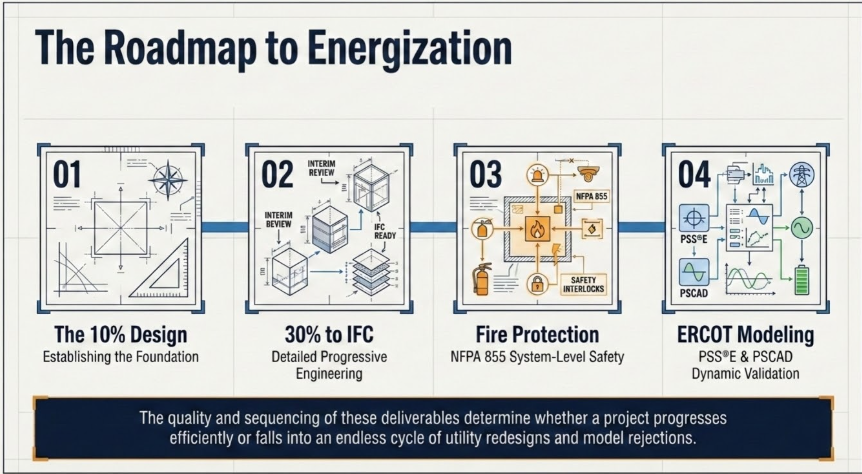
This guide explains the four primary engineering workstreams required to move a utility-scale BESS project from concept through construction:
- The 10% design package for utility and interconnection submission
- The progressive 30%, 60%, 90%, and IFC design stages
- System-level fire protection engineering under NFPA 855
- PSS®E and PSCAD dynamic model development for ERCOT
It also includes anonymized project examples and answers to the questions battery storage developers most frequently raise.
1. The 10% Design Package: A Small Submission With Major Consequences
The 10% design package, sometimes described as a conceptual or screening-level design, is usually the first engineering package requested by transmission service providers such as TNMP, AEP Texas, Oncor, and CenterPoint.
Although the package is intentionally preliminary, the information it establishes becomes the foundation for future interconnection studies, utility agreements, equipment selections, and detailed design work. Errors at this stage can create far more than a simple revision. They may invalidate study assumptions and force substantial rework months later.
A complete 10% package for a utility-scale BESS commonly includes the following elements.
Preliminary Single-Line Diagram
The preliminary single-line diagram should illustrate the electrical path from the battery racks and DC system through the power conversion systems, medium-voltage transformers, switchgear, metering equipment, and proposed point of interconnection.
At the 10% stage, the purpose is to establish the system topology and major equipment ratings. Final conductor sizing and detailed protection design normally come later.
Conceptual Site Layout and General Arrangement
The conceptual layout should position the battery containers, PCS skids, medium-voltage transformers, switchgear, collector system, and interconnection facilities on the actual project parcel.
NFPA 855 separation requirements, emergency access, and fire department access should influence the layout from the beginning.
One of the most common early-stage errors is arranging equipment only for electrical convenience. A layout may appear efficient from a cable-routing perspective but later fail fire-code separation or emergency-access requirements. When that happens after utility review has already started, the project may require extensive redesign.
Equipment Data
The package should include available manufacturer data for the battery systems and power conversion equipment.
Relevant information normally includes:
- Active and reactive power capability
- AC and DC voltage ranges
- PCS operating limits
- Certification status
- UL 1741 documentation
- IEEE 1547 information where applicable
- UL 9540A testing data for the selected battery product
Preliminary Sizing Calculations
The preliminary calculation package should demonstrate how the project will achieve its required AC output at the point of interconnection.
The calculation should consider:
- PCS conversion efficiency
- Battery system losses
- Auxiliary loads
- DC-to-AC ratio
- Required operating duration
- Available energy at the POI
For example, a 10 MW / 20 MWh system should clearly identify that it is being designed around a two-hour operating duration. That duration later affects ERCOT registration, operational data, and model parameters.
Grid Interface and Operating Plan
The 10% package should identify the proposed point of interconnection, including the interconnection voltage and the applicable substation, feeder, or transmission facility.
It should also describe the intended operating profile. In ERCOT, battery storage facilities are commonly registered and operated under the Energy Storage Resource framework.
Why Speed Matters at the 10% Stage
Interconnection development is heavily influenced by queue timing. Every week spent preparing the initial package may affect queue position, study scheduling, procurement timing, and the overall commercial schedule.
For a well-defined, containerized BESS project with equipment data and POI information available, the 10% package should normally be completed in days rather than weeks.
With established drawing standards, repeatable calculation templates, and an experienced storage engineering team, a submission-ready package can often be delivered within seven calendar days from notice to proceed.
The First Question That Must Be Resolved
Before developing drawings, the project team should confirm the applicable interconnection pathway with the TSP.
Depending on project size, POI voltage, and facility configuration, a Texas BESS may proceed through:
- A distribution-level interconnection process administered by the TSP
- The full ERCOT generation interconnection process
This decision affects the content of the initial package, the studies that follow, the required utility coordination, and whether detailed dynamic modeling obligations are triggered.
Projects positioned close to common size or voltage thresholds should resolve this question before engineering begins. It is not a minor administrative issue. It can change the entire downstream scope.
2. From 30% Design to IFC: Building a Package That Survives Review
A common and expensive misunderstanding is the assumption that UL 9540A testing automatically makes the project fire-code compliant.
UL 9540A is a test method used to evaluate thermal-runaway behavior at the cell, module, unit, and installation levels. It generates product-specific fire and gas data.
It does not independently establish that the complete project site complies with NFPA 855.
NFPA 855 governs the installation of stationary energy storage systems at the system and site level. Compliance requires engineering analysis that uses UL 9540A results as one of several design inputs.
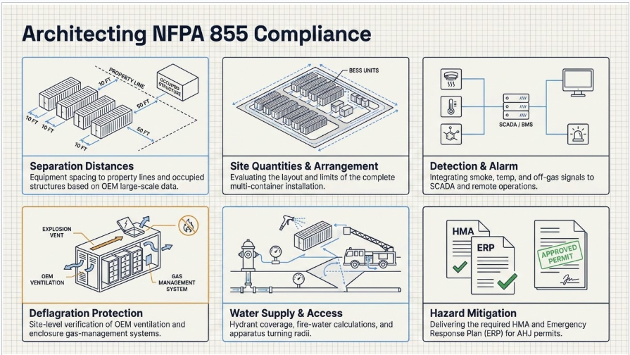
System-level NFPA 855 engineering for a utility-scale BESS generally includes the following areas.
Separation Distances
The design must evaluate spacing:
- Between battery units
- Between battery systems and property lines
- Between battery systems and occupied structures
- Between battery systems and nearby exposures
- Between equipment and emergency-access areas
Where reduced spacing is proposed, the design team must determine whether the OEM’s large-scale UL 9540A results support that arrangement.
Site Quantities and Equipment Arrangement
NFPA 855 requirements may vary depending on the total energy capacity, equipment grouping, installation configuration, and site layout.
The project team must evaluate how the standard applies to the complete multi-container installation, not simply to an individual battery enclosure.
Detection and Alarm Integration
Container-level detection systems must be coordinated with site-level alarm and notification systems.
The design should establish how smoke, temperature, off-gas, and other detection signals are communicated to:
- Site controls
- Plant SCADA
- Local alarms
- Remote operators
- Emergency responders
Deflagration Protection
The OEM’s gas-management, ventilation, and deflagration-protection approach must be reviewed against the requirements applicable to the actual installation.
A product-level design may require additional site-level verification depending on enclosure arrangement, spacing, and emergency planning assumptions.
Water Supply and Fire Department Access
The project should assess:
- Available hydrant coverage
- Fire-water supply
- Access-road widths
- Turning radii
- Apparatus staging areas
- Emergency clearances
- Site-entry controls
These requirements should be coordinated with the local fire department and authority having jurisdiction.
Hazard Mitigation and Emergency Planning
Authorities increasingly require formal project documentation before issuing permits.
Common deliverables include:
- Hazard Mitigation Analysis
- Emergency Response Plan
- Site-specific shutdown procedures
- Emergency contact information
- Equipment isolation procedures
- Fire department coordination documentation
Two Practical Lessons From BESS Project Experience
The first lesson is to perform NFPA 855 engineering at the same time as the 10% layout.
Fire separation, emergency access, equipment arrangement, and response requirements should shape the general arrangement from the first design revision. Adding these requirements after the layout has been completed is a frequent cause of schedule delay, particularly on constrained parcels.
The second lesson applies to portfolios that use equipment from more than one OEM.
Each battery product should be evaluated separately. UL 9540A results are product-specific and cannot automatically be transferred from one battery enclosure design to another, even when both systems have similar MW and MWh ratings.
After the initial design basis has been accepted, the project normally progresses through formal design stages such as 30%, 60%, 90%, and Issued for Construction.
These stage gates are not unnecessary documentation exercises. They allow electrical, civil, structural, protection, utility, vendor, and permitting inputs to develop in parallel without creating uncontrolled rework.
30% Design: Establishing the Design Basis
At the 30% stage, the preliminary single-line diagram develops into a more complete electrical drawing.
Typical additions include:
- Transformer impedances
- Switchgear ratings
- Preliminary protection zones
- Developed equipment ratings
- Initial metering and interconnection details
The conceptual site layout should also become a dimensioned equipment arrangement.
A formal design criteria document should establish the codes, standards, utility requirements, project assumptions, and equipment criteria that will govern the remaining engineering work.
This is also the stage where meaningful coordination with civil and structural engineers must begin. Key interface items include:
- Foundation loading
- Container anchorage
- Equipment pad requirements
- Trench routing
- Conduit routing
- Cable-entry locations
- Structural clearances
- Drainage and grading constraints
60% and 90% Design: Completing the Engineering Core
Most detailed calculations and equipment coordination occur between the 60% and 90% milestones.
The design scope commonly includes:
- AC and DC collection system design
- Cable sizing and ampacity calculations
- Voltage-drop calculations
- Cable schedules
- Grounding design based on site soil resistivity
- Lightning protection
- IEEE 80 grounding calculations
- Station service transformer design
- Auxiliary power distribution
- Panelboards and control power
- UPS systems for protection and control equipment
- MV transformer specifications
- Switchgear specifications
- PCS technical review
- Vendor drawing review
- Protection and metering single-line diagrams
- Relay one-line diagrams
- AC and DC control schematics
- CT and VT selection
- Protection-zone development
Every formal review stage should also include a controlled comment-resolution process.
Comments should not simply disappear from one revision to the next. Each comment should be documented, assigned, resolved, and closed. Untracked comments frequently return during utility review, construction, or commissioning.
IFC Design: The Construction-Ready Package
The Issued-for-Construction package should incorporate all final utility, owner, vendor, and authority-having-jurisdiction comments.
The completed design should be sealed by a Professional Engineer licensed in the state where the project is located. For a Texas facility, a Texas-licensed P.E. must take responsible charge of the engineering work.
The IFC package also becomes the reference against which ERCOT dynamic models are verified.
Transformer impedances, collector-system equivalents, equipment ratings, and facility topology represented in the model must match the final design documents. Any inconsistency between the drawings and model data will eventually be identified, often during the most schedule-sensitive stage of review.
Why BESS Design Is Different From Solar or Conventional Substation Design
Battery storage facilities concentrate an unusually large amount of medium-voltage infrastructure within a limited area.
A small site may contain:
- Multiple battery containers
- Several PCS units
- Medium-voltage transformers
- Switchgear
- Auxiliary power equipment
- Protection systems
- Control systems
- Fire-protection infrastructure
All of this may be installed on less than an acre.
Because the facility is so compact, electrical, civil, structural, and fire-protection requirements are closely interconnected. Moving a battery container a few feet to improve cable routing may violate a fire-separation requirement. Revising a foundation because of geotechnical conditions may force changes to a duct bank or cable trench.
Teams that treat a BESS as nothing more than a small substation connected to batteries often discover these conflicts only after substantial design work has already been completed.
3. System-Level NFPA 855 Compliance: What UL 9540A Testing Does Not Address
4. ERCOT PSS®E and PSCAD Models: Where Projects Can Quietly Lose Months
ERCOT applies some of the most detailed inverter-based resource modeling requirements in North America.
Depending on the project’s interconnection pathway, a BESS developer may need to provide:
- A site-specific PSS®E RMS dynamic model
- A PSCAD electromagnetic transient model
- Supporting model documentation
- Quality-screening evidence
- Benchmarking between RMS and EMT platforms
Both models must be technically correct and capable of passing the applicable review process.
OEM Model Collection and Review
Site-specific plant models are typically assembled using OEM-provided PCS and plant-controller models.
Obtaining usable vendor models is frequently the critical schedule path.
Common issues include:
- Late model delivery
- Encrypted files
- Incorrect software versions
- Incomplete documentation
- Parameter mismatches
- Models that do not correspond to the selected firmware
- Parameters that conflict with the equipment datasheets
The OEM model request should begin immediately after equipment selection rather than waiting until the interconnection study requires the files.
Site-Specific Model Assembly
The OEM control blocks must be combined with the actual electrical characteristics of the project.
This includes:
- Transformer impedances
- Collector-system equivalents
- Plant controller settings
- Facility ratings
- Point-of-interconnection data
- Protection and control parameters
- Current design topology
Models should not be built from generic or typical project assumptions.
A model developed from placeholder data may initially appear usable, but inconsistencies will eventually be discovered when it is compared with the drawings, equipment data, or study assumptions. Correcting those differences later normally requires more effort than building the site-specific model correctly from the beginning.
Benchmarking and Quality Screening
Before submission, the models should be tested against the same types of checks that utility and ERCOT reviewers are likely to perform.
Typical screening includes:
- Flat-start initialization
- Load-flow convergence
- Dynamic initialization
- Disturbance playback
- Voltage ride-through
- Frequency ride-through
- Fault response
- Active and reactive power response
- Plant-controller behavior
- RMS-to-EMT benchmarking
Models that are submitted without internal screening are more likely to be rejected or returned for correction.
Documentation and Review Support
A complete model package should include:
- Dynamic data sheets
- Model user documentation
- Parameter definitions
- Version information
- Validation records
- Benchmarking results
- Assumption logs
- Responses to reviewer comments
The engineering team should also remain available throughout the model-review cycle. Model acceptance is often iterative, and timely responses help prevent individual comments from extending the project schedule.
Multi-Project Portfolios
A developer building several facilities with different OEM equipment should plan for a separate model package for each project.
A model developed for one manufacturer’s PCS and controller platform cannot be meaningfully reused for another OEM’s equipment. Even projects with identical ratings may have materially different controls, limits, protection logic, and dynamic behavior.
The portfolio budget and schedule should account for those differences.
ERCOT Registration Data Must Also Align
Dynamic models are only one part of ERCOT project data.
Resource registration information should remain consistent with:
- Interconnection applications
- Design drawings
- Equipment ratings
- Dynamic models
- Plant operating limits
- Storage duration
- ESR registration parameters
Differences between the registered capacity, model values, and construction drawings are a common source of late-stage comments.
5. Case Studies
Client names and specific project locations have been withheld to maintain confidentiality. The following examples represent work completed by our firm and key technical personnel.
Case Study A
Utility-Scale BESS Electrical Design for 385 MW and 100 MW / 400 MWh Facilities
Challenge
Utility-scale battery storage projects place substantial medium-voltage infrastructure within highly compact sites and aggressive development schedules.
The engineering package must coordinate:
- Inverters
- Battery systems
- Transformers
- Switchgear
- Auxiliary power
- Protection
- Controls
- Cable routing
At the same time, the drawings must satisfy applicable IEEE, IEC, NEC, owner, and interconnecting-utility requirements.
Approach
Complete electrical design packages were developed across multiple project stages.
The scope included:
- Single-line diagrams
- General arrangements
- Equipment layouts
- Panel schedules
- Cable-routing plans
- Preliminary design packages
- IFC packages
- Client-submission packages
- Vendor drawing review
- Datasheet review
- Engineering QA/QC
- Controlled comment resolution
Outcome
IFC-level documentation was delivered for storage projects ranging from approximately 2.5 MW distributed facilities to a 385 MW utility-scale project.
The same structured stage-gate process was applied across projects of significantly different sizes, helping maintain design consistency, technical quality, and review control.
Case Study B
PSS®E Dynamic Model Development and Compliance Testing for a 160 MW ERCOT Power-Electronic Facility
Challenge
Large power-electronic facilities can respond to grid disturbances within only a few electrical cycles.
Their behavior may include:
- Rapid curtailment
- Ride-through action
- Protection trips
- Reconnection logic
- Control interactions
- Active and reactive power changes
Conventional models may not accurately represent this behavior.
ERCOT required the project’s dynamic response, including trip, ride-through, and reconnect characteristics, to be represented and demonstrated before energization.
Approach
A complete PSS®E dynamic model was developed to represent the facility’s power-electronic behavior.
The work included:
- Modeling the facility controls
- Representing protection logic
- Characterizing ride-through performance
- Modeling trip and reconnect behavior
- Aligning model parameters with actual control settings
- Running disturbance scenarios
- Verifying performance against interconnection requirements
- Preparing compliance documentation
Outcome
The project received a submission-ready dynamic model and compliance testing package for one of the grid’s newest and most technically demanding facility categories.
The experience directly supports BESS dynamic modeling performed under similar ERCOT requirements and review processes.
Case Study C
Utility-Scale BESS Protection and Control Design
Challenge
BESS protection presents unique technical challenges because inverter-based resources often contribute limited and controlled fault current.
The protection system must coordinate the facility’s inverter behavior with the interconnecting utility’s protection philosophy.
At the same time, the controls architecture must integrate:
- Battery management systems
- Power conversion systems
- Site controllers
- SCADA
- Utility telemetry
- Protection relays
- Metering systems
The complete design must be capable of passing utility review and supporting field commissioning.
Approach
Protection and control documentation was developed for utility-scale BESS and renewable energy projects.
The scope included:
- Relay one-line diagrams
- Protection schematics
- AC control schematics
- DC control schematics
- Cable schedules
- Communications diagrams
- Relay settings support
- Site acceptance testing support
- Energization assistance
The work was supported by experience that included a multi-substation 345 kV-class protection design program and testing and commissioning leadership on systems up to 765 kV.
Outcome
- The engagement established a repeatable, standards-based protection and control delivery process covering design, relay coordination, testing, commissioning, and energization support.

About the Author:
Sandip "Sonny" R. Patel, P.E.
IEEE Senior Member · Founder & CEO, Keentel Engineering
In 1995, Sonny Patel earned his Electrical Engineering degree from the University of Illinois. But degrees don't build legacies — action does.
For three decades, he has worked the power industry from every side of the table: 16 years as a utility engineer at Exelon/Commonwealth Edison; generation leadership across hydroelectric, industrial steam turbine, and a 9 GW renewable fleet; NERC Regional Entity Senior Compliance Engineer and Audit Team Lead, auditing some of the nation's largest utilities; and testing and commissioning lead on equipment up to 765 kV — the very top of the North American grid.Utility. Generator. Regulator. Consultant. Few engineers have seen all four seats. Fewer still have sat in them.
His experience spans nuclear, hydro, conventional generation, renewables, oil and gas, mining — and today's data centers, where he is authoring a three-book series on data center design. He is a Licensed Professional Engineer in six states and a Licensed Electrical Contractor in Florida (Unlimited EC) — he doesn't just design the work; he's qualified to stand behind its execution.Today, as Founder and CEO of Keentel Engineering, Sonny leads a nationwide team of engineers delivering substation design, power system studies, NERC compliance, and commissioning — done right, coast to coast.Three decades. Every side of the table. One standard: accountable engineering.
Services

Let's Discuss Your Project
Let's book a call to discuss your electrical engineering project that we can help you with.
About the Author:
Sandip "Sonny" R. Patel, P.E.
IEEE Senior Member · Founder & CEO, Keentel Engineering
In 1995, Sonny Patel earned his Electrical Engineering degree from the University of Illinois. But degrees don't build legacies — action does.
For three decades, he has worked the power industry from every side of the table: 16 years as a utility engineer at Exelon/Commonwealth Edison; generation leadership across hydroelectric, industrial steam turbine, and a 9 GW renewable fleet; NERC Regional Entity Senior Compliance Engineer and Audit Team Lead, auditing some of the nation's largest utilities; and testing and commissioning lead on equipment up to 765 kV — the very top of the North American grid.
Utility. Generator. Regulator. Consultant. Few engineers have seen all four seats. Fewer still have sat in them.
His experience spans nuclear, hydro, conventional generation, renewables, oil and gas, mining — and today's data centers, where he is authoring a three-book series on data center design. He is a Licensed Professional Engineer in six states and a Licensed Electrical Contractor in Florida (Unlimited EC) — he doesn't just design the work; he's qualified to stand behind its execution.
Today, as Founder and CEO of Keentel Engineering, Sonny leads a nationwide team of engineers delivering substation design, power system studies, NERC compliance, and commissioning — done right, coast to coast.Three decades. Every side of the table. One standard: accountable engineering.
Leave a Comment
Thank you for contacting us.
We will get back to you as soon as possible.
We will get back to you as soon as possible.
Oops, there was an error sending your message.
Please try again later.
Please try again later.
Related Posts

By SANDIP R PATEL
•
October 13, 2026
Plan data center capacity with land screening, MW-per-acre estimates, grid power availability and interconnection feasibility studies from Keentel Engineering.

By SANDIP R PATEL
•
October 11, 2026
Learn which fault produces the highest current at a bus, why SLG faults can exceed three-phase faults, and how symmetrical components determine fault duty.

By SANDIP R PATEL
•
October 11, 2026
Learn why zero-sequence current pulsates in the dq0 frame, how Park's transformation works, and how inverter controls handle unbalance and ground faults.

By SANDIP R PATEL
•
October 11, 2026
Explore grid inertia, RoCoF and frequency response, with swing equation calculations, frequency nadir analysis and US power system simulation examples.

By SANDIP R PATEL
•
October 11, 2026
Learn transient stability analysis, swing equation, equal-area criterion and critical clearing time with a 345 kV worked example and NERC TPL-001 guidance.

By SANDIP R PATEL
•
October 11, 2026
Learn why inverter controls become unstable in weak grids, how PLL bandwidth and SCR affect stability, and how PSCAD EMT studies identify and mitigate oscillations.

By SANDIP R PATEL
•
October 11, 2026
Learn how STATCOMs improve voltage stability and prevent FIDVR. Explore reactive power sizing, delayed fault clearing, NERC criteria and 138 kV simulation results.

By SANDIP R PATEL
•
October 10, 2026
Learn BESS DC sizing with power, energy, current and C-rate calculations, battery losses, degradation and a 100 MW/400 MWh utility-scale example.

By SANDIP R PATEL
•
October 10, 2026
Learn how BESS ROI is calculated using peak shaving, energy arbitrage, power quality and battery storage economics, with a practical 5 MW/10 MWh example.





