A Coordinated Electric System Interconnection Review—the utility’s deep-dive on technical and cost impacts of your project.
Challenge: Frequent false tripping using conventional electromechanical relays
Solution: SEL-487E integration with multi-terminal differential protection and dynamic inrush restraint
Result: 90% reduction in false trips, saving over $250,000 in downtime
Medium-Voltage Interconnection Engineering
May 11, 2026 | Blog
Studies, substation protection & control, collector routing, and SCADA integration — from the point of interconnection to the point of demarcation.
Connecting new generation or large load to an existing medium-voltage (MV) network demands disciplined interconnection engineering across four linked domains: system studies, substation protection-and-control design, collector and feeder routing, and supervisory control integration. This paper sets out Keentel Engineering’s approach to each, with particular attention to interconnections onto electrically active buses — where existing harmonic filters or reactive-compensation equipment make harmonic and reactive coordination decisive to a safe, code-compliant energization.
1. Introduction
The expansion of utility-scale solar, energy storage, and large industrial loads has increased both the frequency and the complexity of medium-voltage (MV) interconnections. Most occur in the MV class commonly spanning roughly 13.8 kV to 34.5 kV, where a new facility must be joined to an existing network that was not originally designed to accommodate it. Whether the new facility exports to the utility grid or operates behind the fence to offset on-site load, the engineering at the point of interconnection (POI) determines whether energization is safe, code-compliant, and operationally sound.
Interconnection engineering is frequently underestimated because the new generation or load equipment — inverters, transformers, switchgear — is well understood in isolation. The difficulty lies at the seam: the interaction between the new facility and an existing, often brownfield, electrical system whose as-found condition, protection philosophy, and electrical loading must be respected. This paper describes Keentel Engineering’s integrated approach across the four domains that define a complete MV interconnection package — system studies, substation protection-and-control (P&C) design, collector and feeder route engineering, and balance-of-plant (BOP) supervisory control — and the engineering judgment required to deliver them as one coordinated design.
2. Interconnection Topologies and the Point of Interconnection
An MV interconnection begins with a clear definition of the POI and the route from it to the new facility’s demarcation. The POI is commonly established by adding a new MV circuit breaker — vacuum or SF₆, with a disconnect on each side — into an existing switchgear lineup or onto an existing bus. The choice between a dedicated breaker bay, a line tap, or a bus extension is driven by the available fault duty, the host’s protection scheme, physical space, and the operational flexibility the owner requires.
The path from the POI to the facility is rarely a single construction type. In practice it combines segments: insulated MV cable in existing and new cable tray, overhead conductor on pole structures, and underground cable in direct-buried or duct-bank construction. These segments are joined by transition structures — cable-to-overhead risers and overhead-to-underground riser poles — that frequently also house gang-operated air-break switches and revenue or production metering. Each transition is an engineered interface with its own insulation-coordination, grounding, and mechanical requirements. Defining the metering and ownership boundary early, and carrying it consistently through every drawing, prevents the scope ambiguity that often delays interconnection approvals.
3. System Studies
System studies establish the technical basis for a safe energization and for the protection settings that will govern the interconnection in service. The applicable studies, their purpose, and the consensus standards that govern them are summarized below, followed by commentary on the two that most often prove decisive.
| Study | Purpose | Primary Standard |
|---|---|---|
| Load Flow, Reactive Power & Voltage | Steady-state performance, reactive capability, and voltage regulation across the operating range | Utility / ISO criteria |
| Short-Circuit | Available fault duty for equipment rating and protection | IEEE C37 / IEC 60909 |
| Pre-Energization Harmonics | Harmonic emissions and resonance screening at the POI | IEEE 519 |
| Insulation Coordination | Surge-arrester selection and placement at transitions | IEEE 1313 / IEC 60071 |
| Arc Flash | Incident-energy analysis and labeling | IEEE 1584 / NFPA 70E |
| Grounding | Step-and-touch potential and grid design | IEEE 80 / IEEE 81 |
| Protection Coordination & Relay Settings | Selective coordination with existing protection; settings package | IEEE C37 series |
3.1 Harmonics and Resonance on Electrically Active Buses
Inverter-based resources inject harmonic currents that must be evaluated against the existing network at the POI. The evaluation becomes critical when the interconnecting bus already hosts power-factor or harmonic-filter banks, or static VAR compensation with a thyristor-controlled reactor. Tuned filters and compensation equipment reshape the system’s frequency response, and the addition of inverter capacitance and control dynamics can shift resonant points toward characteristic harmonics. A frequency-scan and harmonic load-flow study — screening for resonance and confirming compliance with IEEE 519 voltage- and current-distortion limits at the POI — is therefore not a formality but a gating analysis. Where interactions are identified, mitigation may include filter retuning, detuning reactors, or inverter control adjustments, each of which is best resolved on paper before energization rather than in the field.
3.2 Protection Coordination in a Brownfield Context
A new feeder must coordinate selectively with the host’s existing bus and transformer protection so that a fault on the new circuit is cleared by the nearest device without tripping unrelated load. This requires an accurate as-found protection single-line, current short-circuit data at the interconnecting bus, and a settings package developed and checked against the IEEE C37 family of standards. Behind-the-fence interconnections add a further dimension: the protection must also address islanding, reverse power, and the host facility’s operating and ride-through requirements, which differ materially from a pure grid-export scheme.
4. Substation Interconnection and Protection-and-Control Design
The substation package translates the studies into a constructible interconnection. For a new MV bay added to an existing substation, the physical scope typically includes the general arrangement, elevation views, and structural and foundation design for the new equipment, together with the substation bill of materials. The protection-and-control scope includes the switching diagram, protection single-line, three-line diagrams, AC and DC schematics, control-building and relay-panel layouts, grounding plans and details, conduit plans and schedules, cable and cable-tray details, and wiring diagrams.
On brownfield sites, much of this work is executed by updating owner-furnished CAD or native-PDF drawings so the new bay integrates cleanly into the facility’s existing documentation set. The quality of the as-found record — an accurate single-line, verified fault data, and reliable equipment ratings — is the single largest determinant of design efficiency. Keentel’s practice is to reconcile the as-found drawings against field reality early, so that downstream P&C deliverables rest on a verified basis rather than an inherited assumption.
5. Collector and Feeder Route Engineering
The route from the substation to the facility’s demarcation is engineered as a complete civil-electrical system. It begins with design criteria and a project summary, and develops through cover sheets and plan-and-profile drawings that capture the mixed cable-tray, overhead, and underground construction described in Section 2. Specifications for geotechnical investigation and topographic survey define the field data the design depends on, while an existing-infrastructure location and avoidance plan is essential on congested industrial corridors where the route shares space with roadways, rail, and live utilities.
The electrical core of the route work is conductor sizing: ampacity, loss, derating, and sizing calculations performed in accordance with IEEE 835, the Neher-McGrath method, and ICEA practice, accounting for installation method, mutual heating in tray and duct bank, and soil thermal resistivity. Around this sit the duct-bank design, directional-bore specifications, MV termination specifications, and the grounding, surge-protection, and cathodic-protection details that protect the cable system over its life. Fiber and splice details, phasing drawings, scope-delineation drawings, and construction specifications complete a package that contractors can build without interpretation.
6. Balance-of-Plant SCADA and Communications
Bringing the facility under coordinated control is the final domain. The physical design defines the communication data-flow and architecture, the network and fiber paths, patch panels and splicing, communication-rack and control-enclosure layouts, power wiring, I/O schematics, and field-panel design. The programming scope produces the SCADA point list, the power-plant controller logic, the human-machine interface (HMI), the control narrative and system description, the network plan, the historian configuration, and reporting.
Two principles govern good BOP SCADA design. First, the point list and control narrative are written before the screens, so that the interface reflects a deliberate control philosophy rather than an accumulation of available signals. Second, integration and commissioning are planned from the outset — on-site integration and off-site commissioning support are scoped as engineering tasks, not afterthoughts — because the value of a control system is realized only when it is verified end to end against the as-built plant.
7. Engineering Challenges and Special Considerations
Several recurring conditions separate a routine interconnection from a demanding one, and they are worth naming explicitly because they shape both scope and risk:
- Interconnection onto active buses. Where existing filters or reactive compensation are present, harmonic resonance and reactive coordination must be resolved analytically before energization, as discussed in Section 3.
- Reactive coordination with the host. The new facility’s reactive capability and its plant controller must coordinate with the host’s voltage schedule and any existing compensation, rather than operate in isolation.
- Behind-the-fence versus grid export. The interconnection mode changes which studies, protection functions, and metering requirements apply; treating the two interchangeably is a common and costly error.
- Brownfield congestion and outage coordination. Routing through an operating industrial site requires existing-infrastructure avoidance, outage windows, and verified as-builts, each of which affects schedule as much as design.
- Verified as-found data. Accurate single-lines and current fault data are prerequisites; design built on stale records propagates error through every downstream deliverable.
8. Milestone-Based Delivery and Quality Assurance
Keentel structures interconnection work around progressive design milestones — commonly 10%, 30%, 60%, 90%, Issued-for-Construction (IFC), and As-Built — so that the owner, the host, and any reviewing authority can evaluate the design at defined gates and fund it accordingly. Studies typically progress on a parallel track keyed to 30%, 60%, 90%, IFC, and post-IFC closeout. All deliverables are produced under the oversight and quality assurance of a licensed Professional Engineer, with the engineering seal applied in the jurisdiction the project requires.
| Milestone | Engineering Focus |
|---|---|
| 10% / Design Criteria | Design basis, route concept, survey and geotechnical specifications |
| 30% Design | Studies under way; substation, route, and SCADA developed to a coordinated concept |
| 60% Design | Resonance and coordination drafts; advancing drawings across all packages |
| 90% Design | Near-final drawings, relay settings, and SCADA programming |
| Issued for Construction (IFC) | Sealed drawings, specifications, final studies, and settings |
| As-Built | Record drawings incorporating verified field changes |
9. Conclusion
A medium-voltage interconnection succeeds or fails at the seam between new equipment and an existing system. The studies prove the energization is safe; the substation P&C design makes it constructible; the route engineering carries power reliably to the demarcation; and the SCADA design brings the facility under coordinated control. Treating these as one integrated package — anchored in verified as-found conditions and delivered through disciplined design gates under professional-engineer oversight — is what keeps interconnection projects predictable. Keentel Engineering provides this
full scope, and welcomes the opportunity to discuss how it applies to a specific interconnection.
10. Standards & References
The engineering described in this paper is governed by, and developed in accordance with, the following consensus standards, among others:
- IEEE 519 — Harmonic control in electric power systems
- IEEE 1313 / IEC 60071 — Insulation coordination
- IEEE 1584 / NFPA 70E — Arc-flash hazard analysis and electrical safety
- IEEE 80 / IEEE 81 — Substation grounding and ground-system measurement
- IEEE 835 / Neher-McGrath / ICEA — Cable ampacity and derating
- IEEE C37 series / IEC 60909 — Protection, switchgear, and short-circuit calculation
- NESC and NEC — Overhead/underground construction and electrical installation
Case Studies
The following are anonymized to protect client confidentiality; identifying details, locations, and figures have been generalized.
1 — Behind-the-Fence Solar Tie-In onto an Active Industrial MV Bus
Sector: Heavy industrial host facility, on-site solar. Challenge: The proposed interconnection tied into an existing MV bus that already carried tuned harmonic filters and static VAR compensation. Adding inverter-based generation raised a real risk of harmonic resonance and IEEE 519 non-compliance at the POI. What Keentel did: Built a frequency-scan and harmonic load-flow model of the inverter plant against the existing filters and compensation, screened for resonance, and coordinated reactive behavior with the host's voltage schedule — then carried the result into the protection single-line and relay settings. Outcome: Resonance risk was identified and mitigated analytically before energization, and the interconnection design proceeded to a sealed, constructible package without field surprises.
2 — Utility-Scale Solar Collector & Substation Interconnection Bay
Sector: Utility-scale solar. Challenge: Routing a medium-voltage feeder from a new substation bay to the collection system through a congested corridor sharing space with roadways, rail, and live utilities, using mixed overhead and underground construction. What Keentel did: Delivered the new bay's general arrangement, structural/foundation, and full P&C set, plus the route engineering — plan-and-profile, ampacity/derating calculations, duct-bank and bore specifications, and an existing-infrastructure avoidance plan. Outcome: A coordinated IFC package the contractor could build without interpretation, with the route laid out to avoid existing infrastructure and minimize crossings.
3 — Large Computational Load Transmission/MV Interconnection Support
Sector: Large industrial / data-center class load.
Challenge: A high-capacity load seeking interconnection needed a conceptual single-line covering multiple phased load levels and a modeling package consistent with utility/ISO requirements.
What Keentel did: Developed a phased conceptual single-line and a power-system modeling package (power flow, dynamics, and short-circuit), supported the interconnection application, and responded to utility/ISO modeling review comments — all under licensed PE oversight.
Outcome: A technically sound application basis that let the owner evaluate phased load levels from a single, consistent engineering set during the study process.
Technical FAQ
Where does your scope start and stop?
Typically at the point of interconnection (POI) on the existing network and ending at the new facility's demarcation — the studies, the interconnecting substation bay and protection-and-control (P&C) design, the medium-voltage route, and the balance-of-plant SCADA. Inverter, transformer, and collection-system design beyond the demarcation are usually carried by others, and we coordinate to that boundary.
What changes between a behind-the-fence tie-in and a grid-export interconnection?
Quite a lot. The interconnection mode drives which studies apply, which protection functions are required (islanding, reverse power, ride-through), and what metering is needed. Treating the two interchangeably is one of the most common and costly errors we see, so we confirm the mode before scoping.
Which studies are required, and under what standards?
Depending on the interconnection: load flow / reactive power / voltage; short-circuit (IEEE C37 / IEC 60909); pre-energization harmonics (IEEE 519); insulation coordination (IEEE 1313 / IEC 60071); arc flash (IEEE 1584 / NFPA 70E); grounding (IEEE 80/81); and protection coordination with a relay-settings package (IEEE C37 series).
Why do you emphasize the harmonics study so much?
When the interconnecting bus already hosts power-factor banks, tuned harmonic filters, or static VAR compensation, adding inverter-based resources can shift resonant points toward characteristic harmonics. A frequency-scan and harmonic load-flow study screens for that and confirms IEEE 519 compliance at the POI. It's a gating analysis, not a formality — far cheaper to resolve on paper than in the field.
What do you need from us to start?
The existing single-line and relevant as-builts, editable CAD (or native PDF) of affected drawings, current short-circuit / fault data at the interconnecting bus, and the host's protection, metering, and operating requirements. Verified as-found data is the single biggest driver of design efficiency.
How do you handle brownfield drawings that may be out of date?
We reconcile the as-found documentation against field reality early, before the P&C deliverables are built on it. Much of the substation work is executed by updating owner-furnished CAD so the new bay integrates cleanly into the existing set.
Do you provide PE-stamped deliverables?
Yes. All work is produced under licensed Professional Engineer oversight and QA/QC, with the seal applied in the jurisdiction the project requires.
What does the route engineering cover?
Design criteria, plan-and-profile drawings, ampacity/derating/sizing (IEEE 835 / Neher-McGrath / ICEA), duct-bank design, directional-bore and termination specs, grounding/surge/cathodic-protection details, fiber and splice details, and an existing-infrastructure avoidance plan for congested corridors — across mixed cable-tray, overhead, and underground construction.
What's in the BOP SCADA scope?
Physical design (communication architecture, fiber, network, racks/enclosures, power wiring, I/O, field panels) and programming (point list, power-plant controller, HMI, control narrative, historian, reports), plus on-site integration and off-site commissioning support.
How is the work phased, and how long does it take?
Around progressive design gates — commonly 10 / 30 / 60 / 90 / IFC / As-Built, with studies on a parallel 30/60/90/IFC/post-IFC track. Duration depends on scope and, importantly, on third-party review cycles and owner data turnaround.
What's typically excluded?
Utility/host application fees and deposits, geotechnical investigation and topographic survey (we write the specs; field data is by others), permitting, equipment procurement, and construction/CM.

About the Author:
Sonny Patel P.E. EC
IEEE Senior Member
In 1995, Sandip (Sonny) R. Patel earned his Electrical Engineering degree from the University of Illinois, specializing in Electrical Engineering . But degrees don’t build legacies—action does. For three decades, he’s been shaping the future of engineering, not just as a licensed Professional Engineer across multiple states (Florida, California, New York, West Virginia, and Minnesota), but as a doer. A builder. A leader. Not just an engineer. A Licensed Electrical Contractor in Florida with an Unlimited EC license. Not just an executive. The founder and CEO of KEENTEL LLC—where expertise meets execution. Three decades. Multiple states. Endless impact.
Services

Let's Discuss Your Project
Let's book a call to discuss your electrical engineering project that we can help you with.
About the Author:
Sonny Patel P.E. EC
IEEE Senior Member
In 1995, Sandip (Sonny) R. Patel earned his Electrical Engineering degree from the University of Illinois, specializing in Electrical Engineering . But degrees don’t build legacies—action does. For three decades, he’s been shaping the future of engineering, not just as a licensed Professional Engineer across multiple states (Florida, California, New York, West Virginia, and Minnesota), but as a doer. A builder. A leader. Not just an engineer. A Licensed Electrical Contractor in Florida with an Unlimited EC license. Not just an executive. The founder and CEO of KEENTEL LLC—where expertise meets execution. Three decades. Multiple states. Endless impact.
Leave a Comment
Thank you for contacting us.
We will get back to you as soon as possible.
We will get back to you as soon as possible.
Oops, there was an error sending your message.
Please try again later.
Please try again later.
Related Posts
By SANDIP R PATEL
•
July 27, 2026
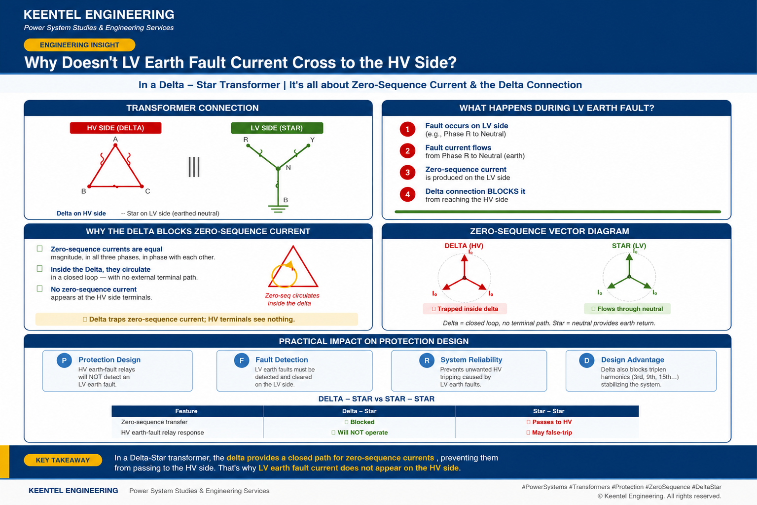
Learn why LV earth-fault current cannot cross a Delta-Star transformer, how zero-sequence current behaves, and what it means for protection design.
By SANDIP R PATEL
•
July 27, 2026
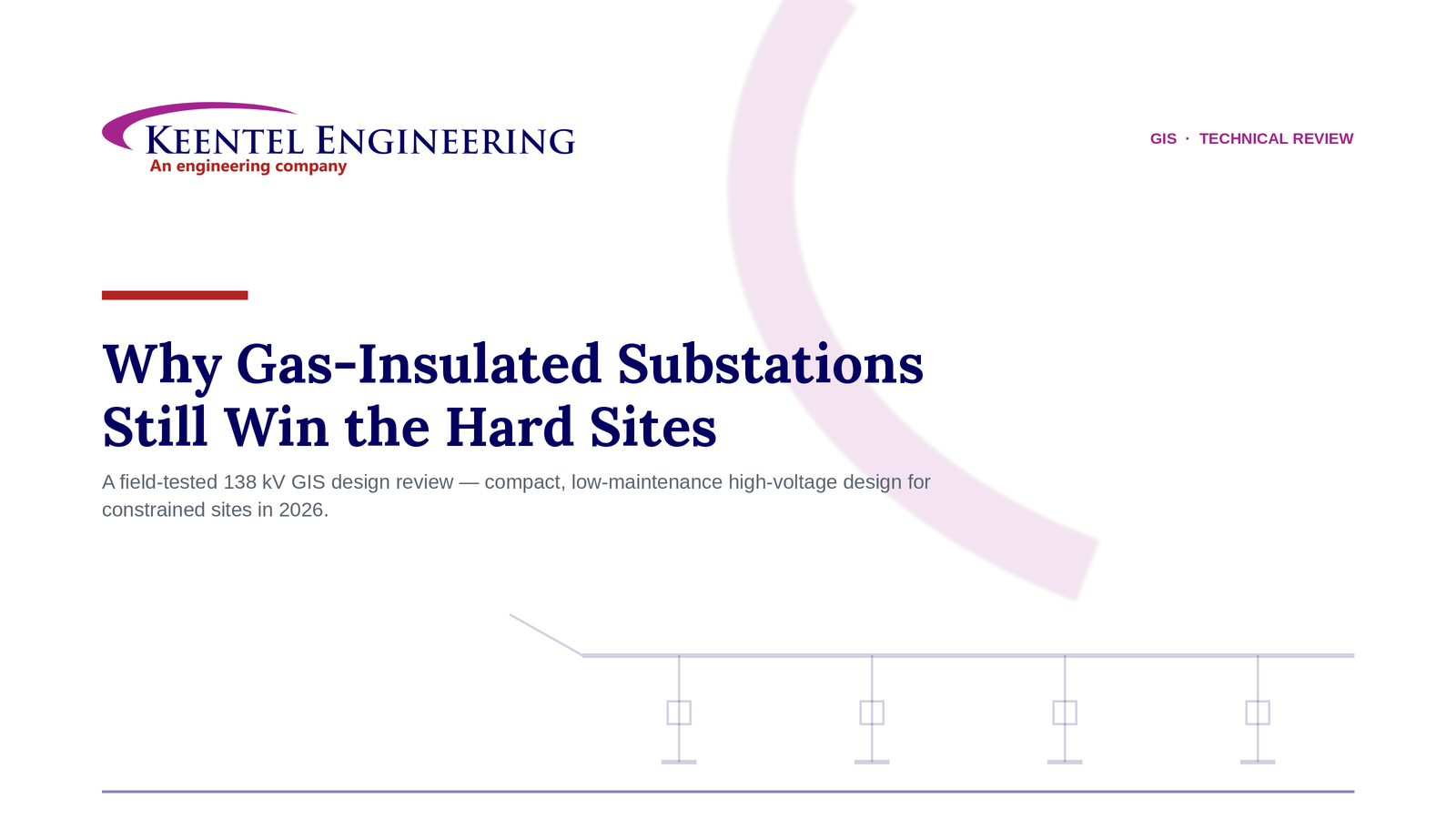
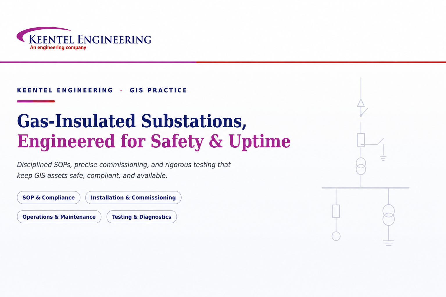
Learn how gas-insulated substations (GIS) improve safety, reliability, and space efficiency with 138 kV design, protection, insulation coordination, and real-world case studies.
By SANDIP R PATEL
•
July 25, 2026
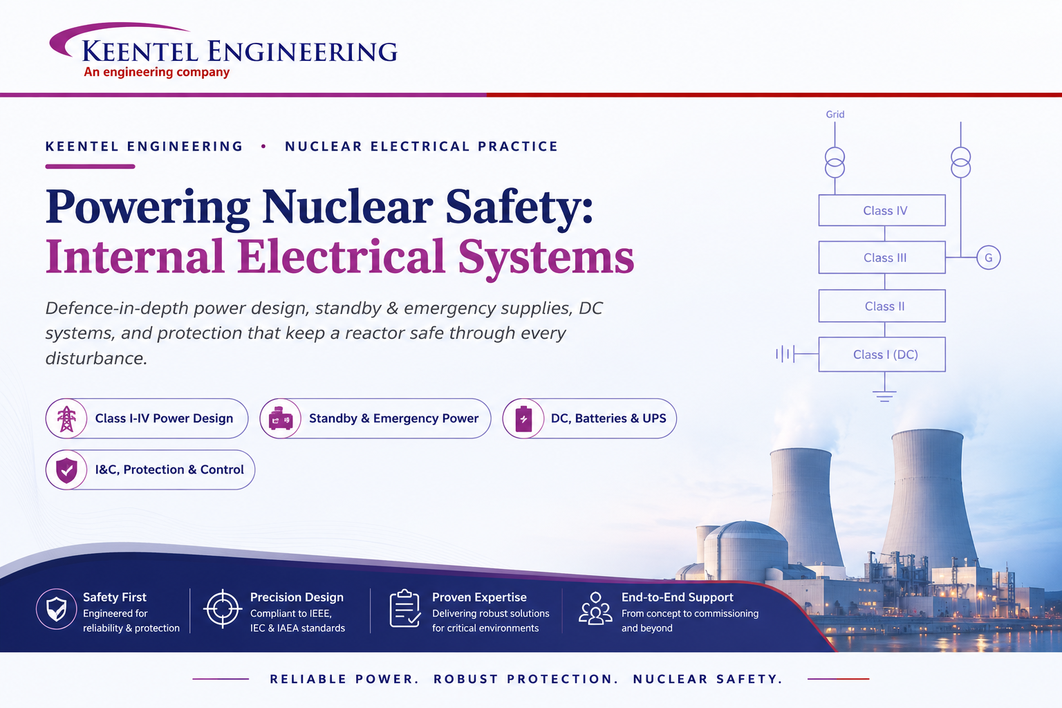
Learn how Class I–IV electrical systems, defence-in-depth, standby and emergency power, DC systems, protection, and load transfer ensure nuclear power plant safety.
By SANDIP R PATEL
•
July 24, 2026
Learn GIS substation safety best practices, SOPs, commissioning, maintenance, interlocking, earthing, and testing to improve grid reliability and uptime.
By SANDIP R PATEL
•
July 23, 2026
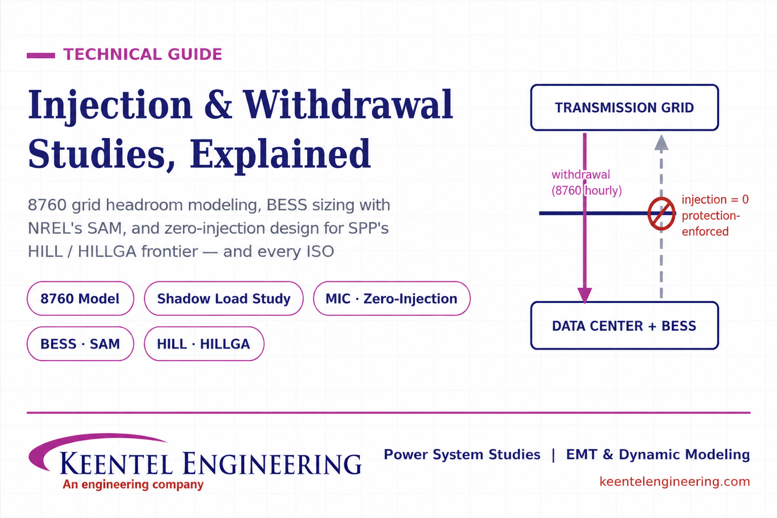
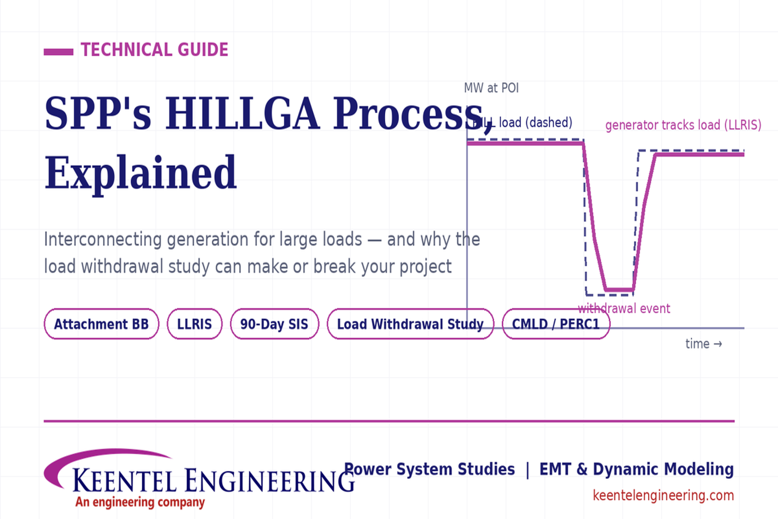
Learn how injection and withdrawal studies, 8760 headroom modeling, zero-injection engineering, and SPP HILLGA improve large load grid interconnections
By SANDIP R PATEL
•
July 21, 2026
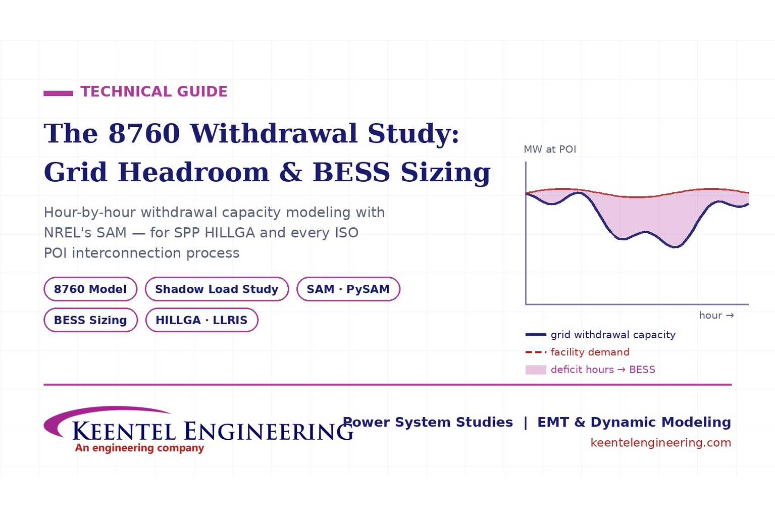
Learn how an 8760 withdrawal study models hourly grid headroom and uses SAM-based BESS sizing for large-load interconnection projects.
By SANDIP R PATEL
•
July 21, 2026
Learn how the SPP HILLGA process supports data center generation interconnection and why an 8760 withdrawal study can determine project success.
By SANDIP R PATEL
•
July 19, 2026
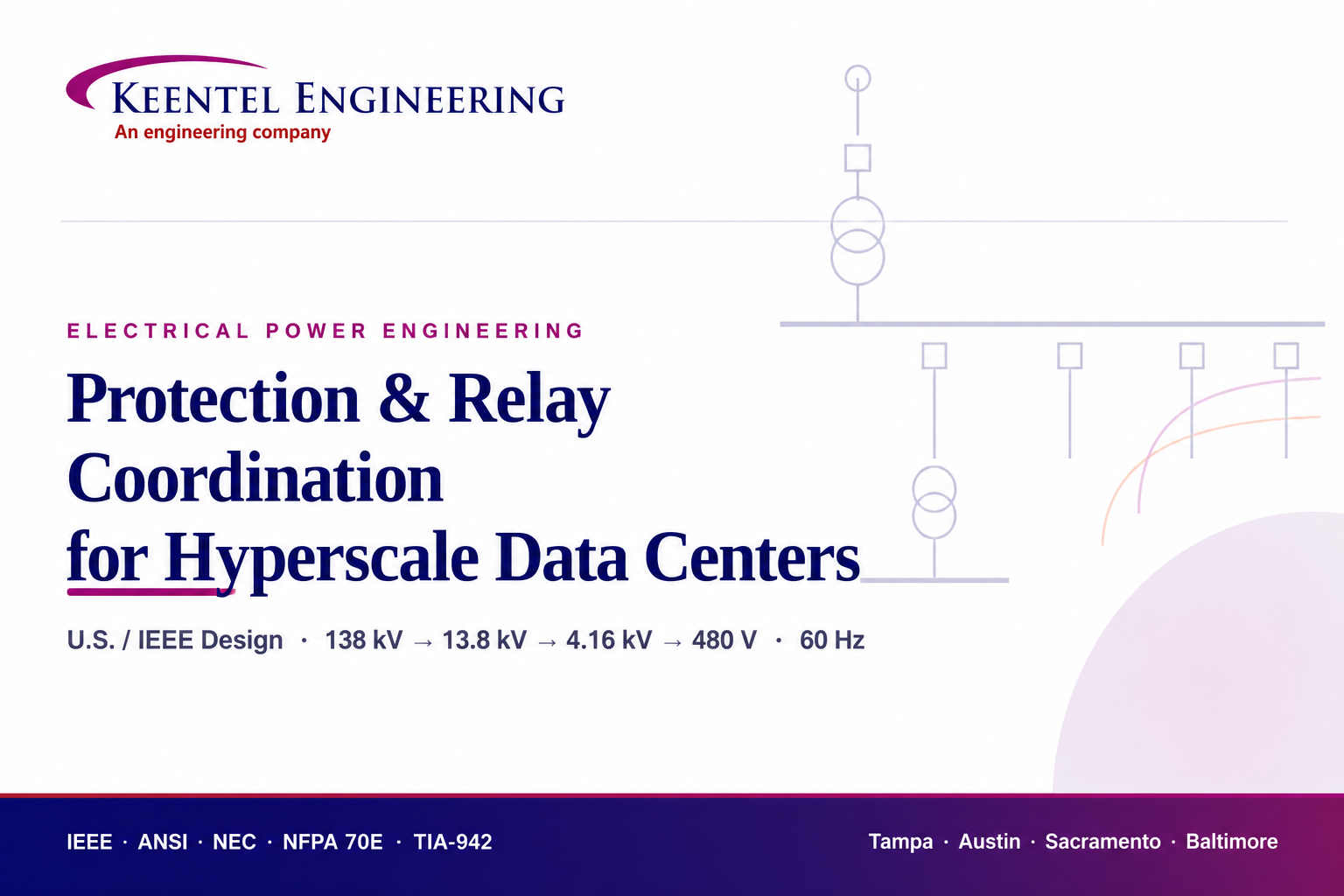
Learn electrical protection and relay coordination for hyperscale data centers with IEEE standards, short-circuit studies, arc-flash analysis, and MV protection.
By SANDIP R PATEL
•
July 18, 2026
Explore Battery Energy Storage System components, including cells, PCS, BMS, EMS, cooling, fire protection, sizing, safety, and grid codes.