
A Coordinated Electric System Interconnection Review—the utility’s deep-dive on technical and cost impacts of your project.
Challenge: Frequent false tripping using conventional electromechanical relays
Solution: SEL-487E integration with multi-terminal differential protection and dynamic inrush restraint
Result: 90% reduction in false trips, saving over $250,000 in downtime
The three operating regions you have to design to
| Device | Output vs voltage | Response | Best suited to | Main limitations |
|---|---|---|---|---|
| Mechanically switched capacitor or reactor | Proportional to voltage squared | Seconds; discrete steps; limited switching operations per day | Steady-state reactive supply, voltage profile, loss reduction | No dynamic capability; step voltage change on switching; capability collapses when most needed |
| Static var compensator | Capacitive branches proportional to voltage squared | A few cycles; continuously controllable | Continuous control where cost matters and deep voltage support is not the driver | Square-law capability loss; harmonic filters are part of the plant and interact with the network |
| STATCOM | Approximately proportional to voltage — constant current capability | One to two cycles closed loop; converter response faster still | Voltage stability margin, weak interconnections, fast disturbance recovery, flicker and unbalance compensation | Higher capital cost; converter losses; adds a converter and its control dynamics to the network |
| Synchronous condenser | Governed by machine capability and excitation | Excitation response in the hundreds of milliseconds; inherent inertial response instantaneous | System strength and inertia, short-circuit contribution, black start support | Rotating plant with maintenance and losses; slower controlled response than a converter |
| STATCOM with energy storage | Reactive as a STATCOM, plus real power within the storage rating | As STATCOM for reactive; real power limited by storage | Where a real power deficiency is part of the problem | Cost and complexity of the storage; different failure and maintenance profile |
Electrical Commissioning: What a Pre-Energization Checklist Leaves Out
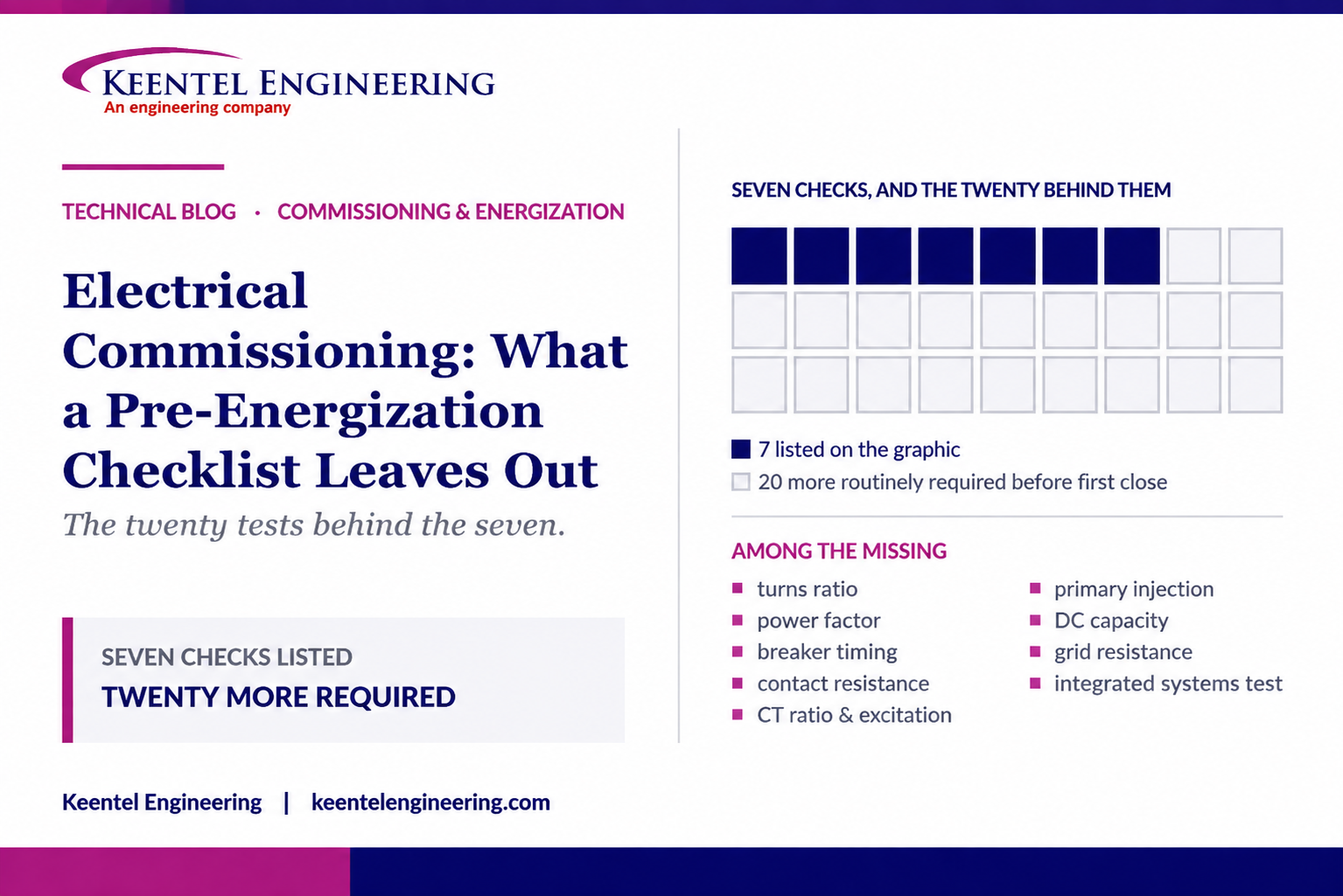
September 20, 2026 | Blog
The Twenty Tests Behind the Seven, Why Lockout Belongs at the Start Rather Than Near the End, and Why the Same Insulation Reading Can Pass or Fail on Reference Temperature Alone
1. Executive Summary
Pre-energization checklists circulate widely in the electrical trades, and most of them are honest, field-earned and useful. The seven-check list this paper works from is one of the better ones. Its items are real, its sequence of test, verify, functionally check, document and then energize is the right shape, and its closing instruction is the single most important sentence anybody has ever written about commissioning: do not energize simply because the test report is complete.
This paper takes that instruction seriously and asks what the test report would need to contain before it could support that decision. The answer is a good deal more than seven items, and the gap is not a criticism of the list. It is the difference between a field aide-memoire and a commissioning program.
Four findings sit at the centre of the paper.
First, a seven-item list is a test list, not a commissioning program. Against the seven checks shown, a conventional acceptance and commissioning scope for the same equipment carries roughly twenty further activities that are routinely required before first close — transformer turns ratio, winding resistance, insulating liquid and dissolved gas baselines, power factor and dissipation factor, breaker timing and travel, contact and bolted-joint resistance, current transformer ratio and excitation, ground grid resistance as distinct from continuity, primary injection of the complete chain, direct current system capacity, phase rotation and synchronising checks, arc flash study verification and labelling, and an integrated systems test. None of these is exotic. All of them are ordinary scope on a project of any size.
Second, there is one genuine sequencing error in the list as drawn, and it is worth correcting because it is repeated in many similar documents. Grounding verification and lockout appear as step six, after the testing. Both belong before the testing. Lockout is not a commissioning step at all; it is the control that spans the entire period and is deliberately released at energization. Placing it at step six describes it as something completed near the end, which is exactly the misunderstanding that puts people in front of equipment they believe is isolated.
Third, insulation resistance the first item, and the most performed test in the industry — is routinely reported in a form that cannot be evaluated. Insulation resistance is strongly temperature dependent, falling by roughly half for every ten kelvin of temperature rise. Correcting the same measurement to a twenty degree Celsius reference rather than a forty degree Celsius reference changes the reported number by a factor of exactly four, at any measurement temperature. A raw reading of 900 megohms taken at thirty-five degrees Celsius becomes 318 megohms referenced to twenty degrees and 1,273 megohms referenced to forty degrees. Against a 1,000 megohm acceptance criterion, the same cable fails or passes depending only on a convention the report frequently does not state.
Fourth, secondary injection proves the relay. It does not prove the system. A relay that has been tested by injecting current at its own terminals has demonstrated that its pickup, timing and logic are correct, and nothing whatsoever about whether the current transformer ratio, polarity, secondary wiring, shorting links and trip path between the primary conductor and the breaker coil are correct. Only primary injection proves that chain, and primary injection is the test most often deleted when a schedule tightens.
The sentence worth taking from this
Every test on a pre-energization list answers a narrow question about one component. Energization is a decision about a whole system, made by a person, on a particular day, with people and temporary equipment still in the vicinity.
The test report is an input to that decision. It is not the decision, and a complete report has never by itself made anything safe.
2. A Sound Test List Is Not a Commissioning Program
It is worth being precise about what a short checklist is for, because the criticism that follows is about scope rather than quality.
A seven-item list is a field aide-memoire. Its job is to be memorable, to be recalled under pressure by somebody standing in front of a switchboard, and to prevent the most common and most consequential omissions. Judged on that job, the list works. Insulation resistance, continuity and phasing, current transformer polarity, relay testing, trip and interlock function, grounding, and a documentation review are exactly the seven things a person should be able to recite.
A commissioning program is a different artefact. It is a scope of work, it is auditable, it defines who witnesses what, it distinguishes factory acceptance from site acceptance from functional testing from integrated testing, and it produces a record that somebody will read years later when the equipment misbehaves. It is written before mobilisation, not recalled on the day.
What the two look like side by side
| Activity group | On a seven-item list | In a commissioning scope |
|---|---|---|
| Insulation resistance | Yes — as a single line | Yes, with test voltage, duration, temperature, reference temperature and acceptance criterion stated |
| Continuity and phasing | Yes | Yes, plus phase rotation and phasing across every point of parallel |
| Current transformer checks | Polarity only | Ratio, polarity, excitation, burden, winding resistance, insulation, and tap verification against the relay setting |
| Relay testing | Pickup, timing, contacts, logic | The same, plus settings verified against the issued file, and end-to-end testing of pilot schemes |
| Proving the chain | Not distinguished | Primary injection of the complete current transformer to trip-coil path |
| Trip and interlock | Yes | Yes, plus trip circuit supervision, second trip coil, breaker failure initiation and direct current capacity |
| Grounding | Continuity | Continuity, plus ground grid resistance, soil resistivity and touch and step potential verification |
| Transformers | Insulation resistance only | Turns ratio, winding resistance, power factor, excitation, liquid tests, dissolved gas baseline, cooling and protection devices |
| Breakers | Trip function | Timing, travel, pole simultaneity, contact resistance, mechanism and operating gas or fluid |
| Cables | Insulation resistance | Withstand or partial discharge testing appropriate to the class, plus shield and bonding verification |
| System behaviour | Not addressed | Integrated systems test under transfer, loss of source and failure scenarios |
| Safety study | Not addressed | Arc flash and coordination study verified as-built, labels installed |
The right conclusion is not that the seven-item list is wrong. It is that a list of this kind should be understood as the last thirty seconds of thinking before a switching operation, and never as the definition of scope. When it is used as the latter which happens most often on small projects, on fast-track work, and on the parts of a large project that were added late — the omissions above become the punch list that the first fault discovers.
A useful test of any checklist
Ask what would happen if every item on it passed and the item you are worried about was never performed. If the answer is that the equipment would still be energized, the list is not a scope.
Ask also what the acceptance criterion is for each line. A check with no stated criterion is an observation, not a test.
3. The Sequencing Error: Lockout Is Not Step Six
This is the one substantive correction in this paper, and it applies to a large family of similar documents rather than to any single one.
Placing grounding verification and lockout at step six, after insulation resistance, continuity, current transformer work, relay testing and trip testing, describes a sequence that cannot be performed as written. Every one of the preceding five activities requires the equipment to be isolated and grounded before it starts. A person cannot megger a cable, land test leads on a current transformer secondary, or operate a breaker trip coil on equipment that has not already been isolated, proven dead and grounded.
So the grounding and isolation content of step six is not a step at all. It is a precondition of steps one through five, and it should be drawn as such.
What actually belongs where
The honest sequence has three distinct phases, and the isolation control behaves differently in each.
| Phase | What happens | State of the isolation control |
|---|---|---|
| Before any testing | Isolate, prove dead, apply safety grounds, establish lockout, issue the work authorisation | Applied and held |
| During testing | All electrical testing. Temporary test grounds and leads are applied and removed under the same control | Held throughout; individual grounds moved under a controlled procedure |
| Before energization | Remove temporary test leads and safety grounds, reinstall covers and barriers, clear personnel, walk down, verify the configuration, then release the isolation control | Deliberately and formally released — the final act, by named authority |
The second row is where most of the real risk lives, because it is the phase in which safety grounds legitimately come off and go back on, and in which temporary test equipment is connected to the primary circuit. The control has to survive that.
The third row contains the item that the source list does get exactly right, and it deserves emphasis rather than correction: removing temporary test leads and safety grounds is an explicit, checked, named-person action. Grounds left in place at energization produce a bolted three-phase fault at the instant of closing, on equipment that is brand new, with people standing nearby who have just been told the system is ready.
Verification of grounding is a separate matter
The other half of step six, confirming equipment grounding and bonding, is a genuine verification activity and it does belong in the test scope. But it is worth separating two things that the phrase "ground system continuity" runs together.
- Bonding continuity is a low-resistance measurement between an equipment enclosure, frame or cable armour and the ground grid or ground bus. It proves the connection exists and is sound. It is typically a micro-ohm or low-ohm measurement.
- Ground grid resistance is a measurement of the resistance of the whole grounding system to remote earth, made by a fall-of-potential or equivalent method. It proves something entirely different — how the site will behave when fault current flows into the earth — and it cannot be inferred from continuity.
A site can have perfect bonding continuity everywhere and an inadequate grid, or a good grid and one critical bond missing. Both are required, they are measured by different methods, and a checklist line reading "confirm grounding continuity" only covers the first.
4. Insulation Resistance: Most Performed, Most Misread
Insulation resistance is the first item on almost every pre-energization list, and with good reason. It is fast, it is non-destructive, the instrument is inexpensive and portable, and it catches gross problems — moisture, contamination, a forgotten ground, a crushed cable, a wrong connection — with high reliability.
It is also the test most often reported in a form that nobody downstream can evaluate, and the test most often asked to answer questions it cannot answer.
What the measurement is
A direct voltage is applied between the conductor and ground, and the resulting current is measured after a defined interval. The ratio gives a resistance. The current has several components, and only one of them is what the test is nominally about:
- Capacitive charging current, which is large initially and decays within seconds.
- Absorption or polarisation current, which decays over minutes as the dielectric polarises. This is the component that makes the reading time-dependent and makes a timed index meaningful.
- Surface leakage current, across the surface of terminations and bushings, which is dominated by contamination and humidity rather than by the insulation itself.
- True conduction current through the volume of the insulation, which is the quantity of interest and is usually the smallest of the four.
Two consequences follow immediately. A reading taken at an arbitrary time is meaningless unless the time is stated, because the absorption component is still decaying. And a low reading may be telling you about a dirty bushing surface rather than about the insulation, which is why a guard terminal exists on a good instrument and why wiping down terminations before testing is not cosmetic.
Test voltage matters, and so does what is connected
The applied direct voltage is selected from the equipment rating, and applying more than the insulation system or the connected devices can tolerate turns a diagnostic test into a destructive one. The recurring field failure is not over-stressing the insulation; it is forgetting what is connected to the circuit. Surge arresters, capacitive voltage transformers, electronic trip units, relays, meters, variable frequency drive output filters and motor terminal surge capacitors all provide either a conduction path that ruins the reading or a component that the test voltage destroys.
Before the leads go on
Establish the correct test voltage from the equipment rating and the applicable standard, and write it on the record.
Disconnect or isolate everything that cannot tolerate it, and list what was disconnected on the record so the next person knows what the measurement actually included.
Record the measurement temperature, the reference temperature, the duration and the humidity. A number on its own is not a result.
5. The Factor of Four: Temperature and Reference Temperature
Insulation resistance falls as temperature rises, and it falls steeply. The working rule across the industry is that the resistance approximately halves for every ten kelvin increase in temperature, which makes the correction:
IR_corrected = IR_measured × 2 ^ ( ( T_reference − T_measured ) / 10 )
with temperatures in degrees Celsius. That exponential is unforgiving. A fifteen degree difference between a cool morning test and a warm afternoon test changes the reading by a factor of nearly three on the same, unchanged insulation.
The correction factors
| Measured at | Factor to reference 20 °C | Factor to reference 40 °C | Ratio between the two |
|---|---|---|---|
| 10 °C | 2.00 | 8.00 | 4× |
| 15 °C | 1.41 | 5.66 | 4× |
| 20 °C | 1.00 | 4.00 | 4× |
| 25 °C | 0.71 | 2.83 | 4× |
| 30 °C | 0.50 | 2.00 | 4× |
| 35 °C | 0.35 | 1.41 | 4× |
| 40 °C | 0.25 | 1.00 | 4× |
| 45 °C | 0.18 | 0.71 | 4× |
The last column is the finding. The choice of reference temperature alone multiplies or divides the reported number by exactly four, at every measurement temperature, because two to the power of the twenty-kelvin difference divided by ten is four. It is not an approximation and it does not vary with the equipment.
What that does to a pass or fail
Consider a medium-voltage cable with an acceptance criterion of 1,000 megohms, and a raw field reading of 900 megohms.
| Conductor temperature at test | Corrected to 20 °C | Verdict | Corrected to 40 °C | Verdict |
|---|---|---|---|---|
| 25 °C | 636 MΩ | Fail | 2,546 MΩ | Pass |
| 30 °C | 450 MΩ | Fail | 1,800 MΩ | Pass |
| 35 °C | 318 MΩ | Fail | 1,273 MΩ | Pass |
| 40 °C | 225 MΩ | Fail | 900 MΩ | Fail |
| 45 °C | 159 MΩ | Fail | 636 MΩ | Fail |
Three of the five rows change verdict on the reference temperature alone. The insulation did not change, the instrument did not change, and the raw reading did not change. What changed was a convention that a great many field reports never state.
The practical rules
- State the measurement temperature. Not the ambient air temperature — the temperature of the insulation being measured, which on a cable that has been in the sun or a transformer that has just been de-energized is not the same thing.
- State the reference temperature and the correction method used, and use the one the governing standard and the acceptance criterion assume. A criterion and a corrected value referenced to different temperatures cannot be compared.
- Record the raw reading as well as the corrected one, so that a later reviewer can re-derive it against a different criterion without repeating the test.
- For trending across years, correct everything to one reference temperature and keep it. A trend built from inconsistently referenced numbers is noise.
Why this matters more for trending than for acceptance
A single acceptance measurement usually has enough margin that a factor of four does not change the answer. Trending does not have that luxury: a real degradation of thirty percent over five years is completely invisible underneath an uncorrected seasonal temperature swing.
Most of the diagnostic value of insulation resistance is in the trend. That value is destroyed by inconsistent temperature handling more often than by anything else.
6. Polarization Index: When a Failing Number Is a Healthy Winding
Because the absorption current decays over minutes, the ratio of the ten-minute reading to the one-minute reading carries information that neither reading carries alone. That ratio is the polarization index, and a companion ratio at sixty and thirty seconds is the dielectric absorption ratio.
PI = IR at 10 minutes / IR at 1 minute
The logic is sound. Clean, dry insulation continues to polarise, so the resistance keeps climbing and the ratio is comfortably above one. Wet or contaminated insulation is dominated by a conduction path that does not change with time, so the reading flattens almost immediately and the ratio approaches unity. A widely used minimum acceptance value is 2.0 for the common thermal classes.
Where the rule breaks
The trap is that the ratio also approaches unity when the insulation is so good that there is almost nothing to measure. A modern dry epoxy-mica winding can have a one-minute reading in the tens of thousands of megohms, with a leakage current at the very bottom of the instrument's range and essentially no measurable change over ten minutes.
| Condition | IR at 1 min | IR at 10 min | PI | Correct reading of the result |
|---|---|---|---|---|
| Wet or contaminated | 300 MΩ | 350 MΩ | 1.17 | Genuinely poor — dry out and retest |
| Marginal | 800 MΩ | 1,400 MΩ | 1.75 | Investigate; trend against history |
| Good older winding | 1,000 MΩ | 2,600 MΩ | 2.60 | Healthy, index informative |
| Modern dry epoxy-mica | 18,000 MΩ | 19,500 MΩ | 1.08 | Excellent — the index is not meaningful here |
The fourth row would be rejected by a blanket rule requiring an index of at least two, and rejecting it would be wrong. The governing standard for rotating machine insulation resistance recognises this directly and provides that the index need not be evaluated when the one-minute resistance, corrected to the reference temperature, is very high — a threshold in the region of 5,000 megohms is the commonly cited figure.
The engineering point is more general than the specific threshold. A ratio test is only meaningful when both terms are measurable. When the denominator is at the noise floor of the instrument, the ratio is measuring the instrument, not the insulation. Any acceptance criterion written as a bare numerical threshold, without the condition under which it applies, will eventually reject something healthy.
7. What Insulation Resistance Cannot Tell You
The most important limitation of the first item on the checklist is what it does not detect. Insulation resistance applies a direct voltage of a few kilovolts across the whole insulation system and measures a bulk leakage. It is excellent at finding a problem that affects the bulk water, dirt, a carbon track, a wrong connection. It is close to blind to a localised defect in an otherwise sound dielectric.
That matters because localised defects are precisely how modern extruded insulation fails. A void in a splice, a knife cut in a semiconducting screen, a sharp protrusion at a termination, a piece of contamination the size of a grain of sand none of these produce a measurable change in bulk leakage, and all of them will initiate partial discharge that erodes the insulation until it fails, often within the first months of service.
| Defect or condition | Found by insulation resistance? | What does find it |
|---|---|---|
| Moisture ingress, general contamination | Yes, reliably | Insulation resistance and polarization index |
| Conductor grounded or cross-connected | Yes | Insulation resistance and continuity |
| Surface tracking on a bushing or termination | Often, if severe | Visual inspection, power factor with guard, insulation resistance |
| Bulk ageing and increasing dielectric loss | Weakly | Power factor / dissipation factor, trended |
| Void, cut screen or contamination in a cable accessory | No | Partial discharge measurement, withstand testing |
| Weak spot that will break down above operating stress | No | Withstand test at an elevated voltage appropriate to the class |
| Wrong transformer tap or turns ratio error | No | Withstand test at an elevated voltage appropriate to the class |
| Loose or high-resistance internal connection | No | Winding resistance, contact resistance, thermography under load |
| Deteriorating insulating liquid, incipient thermal fault | No | Liquid dielectric and quality tests, dissolved gas analysis |
| Core-to-frame or shorted laminations | Partly | Excitation current, core insulation test |
The column of noes is the reason the seven-item list needs the twenty items behind it. Each additional test exists because it answers a question no other test answers, and the cost of skipping it is not visible at energization. It becomes visible later, as a failure with no warning, on equipment whose commissioning record says everything passed.
8. Continuity, Phasing and the Tests That Belong With Them
Continuity and phase identification are the second item, and the list is right to place them early. A cable that is continuous, correctly identified and correctly terminated is the foundation of everything downstream. Three additions belong alongside.
Phase rotation is not phase identification
Identifying that a conductor marked A is the same conductor at both ends is one thing. Establishing that the rotation at a switchboard is the same as the rotation at the source it will be paralleled with is another, and it is the one that damages machinery. A motor started on reversed rotation runs backwards; a generator or a transformer paralleled on mismatched rotation or phase angle produces a fault. Rotation must be established at every point where two supplies can be brought together.
Phasing across an open point
Where two sources can be paralleled a tie breaker, a transfer switch, a synchronising point, a temporary generator connection the voltage across the open point must be measured and shown to be near zero before the point is ever closed. This is a live measurement made on energized equipment, it is done with the appropriate rated instrument and personal protective equipment, and it is the last opportunity to catch an error in everything upstream of it. It is also a step that a purely de-energized checklist cannot contain, which is part of why energization is a phased process rather than a single event.
Shields, screens and bonding
On shielded medium-voltage cable, the shield bonding arrangement is an engineering decision single point, both ends, or cross-bonded and it has to be verified as built against that decision. A shield bonded at both ends when the design assumed single-point bonding carries circulating current and derates the cable; a shield left unbonded produces a hazardous standing voltage. Neither is found by a continuity check on the phase conductor.
Cable qualification above the insulation resistance level
For shielded cable above the low-voltage classes, an insulation resistance measurement is a pre-check, not an acceptance test. Field acceptance of installed medium-voltage cable is normally by a withstand test at an elevated voltage, most commonly very low frequency at around 0.1 hertz, often with partial discharge monitoring so that the test yields diagnostic information rather than just a pass or a fail. The applicable field testing guides set out the voltage levels and durations for acceptance as distinct from maintenance, and the acceptance level is the higher of the two. A project that installs new medium-voltage cable and accepts it on a megohm reading has not tested the accessories, which is where the failures are.
9. Current Transformers: Polarity Is One of Six Checks
Item three is current transformer polarity and secondary circuit verification. Polarity matters enormously a reversed current transformer turns a differential scheme into a device that operates on load and restrains on fault but polarity is one of several checks, and the others fail just as silently.
| Check | What it proves | What goes wrong without it |
|---|---|---|
| Ratio | The delivered secondary current corresponds to the primary current at the nameplate ratio | A multi-ratio transformer landed on the wrong tap; every current-based element mis-scaled |
| Polarity | The instantaneous direction of secondary current relative to primary | Directional and differential elements operate backwards |
| Excitation (knee point) | The core will not saturate at the maximum fault current and burden the scheme must survive | Correct behaviour on load, complete failure on a high-current fault |
| Burden and loop resistance | The connected burden is within the accuracy class at fault current | Saturation, delayed operation, mis-coordination |
| Winding and insulation resistance | The winding is sound and not shorted or grounded | Slow ratio error, or a grounded secondary producing a second ground point |
| Tap verification against the relay setting | The ratio physically connected matches the ratio programmed into the relay | Every setting wrong by the ratio error, with no alarm of any kind |
The last row deserves its own emphasis because it is the failure that a full secondary injection program will not catch. Injecting at the relay proves the relay behaves correctly for the current it is given. If the relay is programmed for 1200:5 and the transformer is landed on the 600:5 tap, secondary injection passes perfectly and the scheme is wrong by a factor of two in service.
The one absolute rule
A current transformer secondary must never be open-circuited while primary current is flowing. A current transformer is a current source; opening the secondary removes the path for the secondary ampere-turns that oppose the primary, the core is driven hard into saturation, and the induced voltage across the open terminals rises to a peaky waveform that can reach several kilovolts on a large unit. It is a lethal shock hazard, an insulation failure mechanism and a source of permanent core damage. Short the secondary before opening any part of the circuit, verify the short, and use the shorting facilities in the test switch or terminal block rather than improvised links.
The corollary is the failure mode in the first case study in this paper: shorting links that go in for testing must come out before service, and the only way to prove they came out is to pass real current through the primary and observe it at the relay.
10. Secondary Injection Proves the Relay, Not the System
This section is the single most important addition this paper makes to the source list, because the distinction is not one of degree. The two tests answer different questions, and one of them is much more commonly deleted.
| Secondary injection | Primary injection | |
|---|---|---|
| Where current is applied | At the relay terminals, or at the test switch | Through the primary conductor |
| What is proven | Relay pickup, timing, characteristic, logic, contacts, targets | The complete path: primary conductor, current transformer ratio and polarity, secondary wiring, shorting links, test switches, relay, output contacts and trip coil |
| Current transformer ratio error | Not detected | Detected |
| Wrong current transformer tap | Not detected | Detected |
| Reversed or crossed secondary wiring upstream of the test switch | Not detected | Detected |
| Shorting link left closed | Not detected | Detected |
| Wrong current transformer core used (metering instead of protection) | Not detected | Detected |
| Effort and equipment | One technician, portable test set | Heavy current source, outage, several people |
| Typically deleted when the schedule slips | Rarely | Frequently |
The pattern in that table is consistent: everything secondary injection cannot see is upstream of the point at which the test current is applied. That is not a limitation that can be engineered away by testing more carefully. It is geometric.
When primary injection can reasonably be reduced
Primary injection is expensive and it is not always proportionate. A defensible position is that the complete chain must be proven by real current at least once for every current transformer circuit, and that the proof does not always have to come from an injection set:
- A full primary injection using a high-current source is the reference method and is appropriate for new installations, differential schemes and anything where the consequence of a wiring error is severe.
- Where load current is available, a load check — reading the actual magnitude and phase angle of every current at the relay against a known load and comparing it with the metering and the expected phasor relationships — proves ratio, polarity and wiring with real current and very little equipment. It requires the equipment to be energized, so it is a first-load activity rather than a pre-energization one, and it must be planned as a formal step with the protection still capable of acting.
- For differential schemes, a load stability check — confirming that the differential current is near zero with real
load flowing through the zone — is the definitive proof that the current transformers are correctly rated, tapped, polarised and wired. A scheme that has not had a stability check has not been commissioned.
The commissioning position worth defending
Every protection current transformer circuit is proven with real primary current before the scheme is relied upon — by injection before energization, or by a formal load and stability check immediately after.
What is not acceptable is a scheme that has only ever seen current injected downstream of the point where the errors live.
11. The Trip Path: Why Breakers Actually Fail to Trip
The fifth item on the list covers breaker trip and interlock function. It is correctly placed and correctly described. What sits behind it is a subject in its own right, because when a protection system fails to clear a fault, the relay is usually not the reason.
The direct current system is the protection system
A protective relay with no control power is a decoration. The station battery, its charger, the distribution to each trip circuit and the continuity of that circuit are part of the protection system in every meaningful sense, and they are the parts most likely to be in poor condition.
Consider a conventional 125 volt station battery of sixty lead-acid cells. On float it sits around 130 volts. At the end of its duty cycle, at the standard end voltage of 1.75 volts per cell, it delivers 105 volts — eighty-four percent of nominal. A trip coil drawing twelve amperes through a loop resistance of 1.4 ohms loses a further 16.8 volts in the wiring, so the coil sees about 88 volts, or seventy-one percent of nominal.
That is still acceptable, because trip coils are normally specified to operate down to around fifty-six percent of rated control voltage — 70 volts on a 125 volt system — which leaves roughly 18 volts of margin. But every one of those deductions is real, they compound, and a battery that has lost capacity, a charger that has been in equalise for a year, or a long trip cable run can consume the margin entirely. The breaker then operates perfectly in every test performed with the battery fully charged and fails on the day a fault coincides with a loss of alternating current supply.
| Element of the trip path | What must be verified | Common finding |
|---|---|---|
| Station battery | Capacity by discharge test against the duty cycle, cell voltages, inter-cell connection resistance | Never capacity tested; sized for a duty cycle that no longer matches the load |
| Charger | Output, float and equalise settings, alarms, ability to carry the load with the battery disconnected | Alarms not wired to anything that is monitored |
| Direct current distribution | Selectivity between direct current breakers or fuses, ground detection | A single direct current ground undetected; a second ground causes a spurious trip or blocks tripping |
| Trip circuit wiring | Loop resistance, terminations, that test switches and knife links are in the service position | Test switches left open after commissioning |
| Trip coil | Continuity, operation at reduced voltage, current draw | Never tested below nominal voltage |
| Trip circuit supervision | That it monitors the complete circuit in both breaker positions, and that its alarm reaches somebody | Supervision monitors only the closed position, or alarms to an unmonitored point |
| Second trip coil | Independent circuit, independent supply where required, tested separately | Both coils fed from the same fuse |
| Breaker failure initiation | That the scheme initiates and clears upstream within the set time | Timer set without reference to the actual breaker clearing time |
The question to ask of any trip circuit
If this circuit were open right now, what would tell you? If the answer is "the next fault", the trip circuit supervision is either absent, incorrectly connected, or alarming somewhere nobody looks.
Trip circuit supervision that monitors only the breaker-closed state leaves the circuit unmonitored for the entire period a breaker is open — which includes the whole of commissioning.
12. The Mechanical Half: Timing, Travel and Contact Resistance
A circuit breaker is an electrical device that solves a mechanical problem. Confirming that it trips when the relay says so proves the signal path; it says almost nothing about whether the interrupter will clear a fault.
Timing
Breaker performance is specified in cycles, and at sixty hertz a cycle is 16.67 milliseconds. A five-cycle breaker is required to clear in 83 milliseconds from trip initiation, of which roughly two cycles is the mechanism moving the contacts apart and about one cycle is arcing.
| Quantity | Cycles | Milliseconds at 60 Hz |
|---|---|---|
| Relay operate time, typical instantaneous element | 1 | 16.7 |
| Trip coil energisation to contact part | 2 | 33.3 |
| Arcing time | 1 | 16.7 |
| Three-cycle breaker, total clearing | 3 | 50.0 |
| Five-cycle breaker, total clearing | 5 | 83.3 |
| Eight-cycle breaker, total clearing | 8 | 133.3 |
| Pole discrepancy limit on opening, one sixth cycle | 0.167 | 2.8 |
| Pole discrepancy limit on closing, one quarter cycle | 0.25 | 4.2 |
Those last two rows are the reason a timing test needs a proper travel analyser rather than a stopwatch and a lamp. A pole that is three milliseconds late is invisible to any observation a person can make and is a genuine defect, because it means the breaker is briefly single-phasing the system during every operation.
Travel analysis adds what timing alone does not: contact velocity, overtravel, rebound and damping. A mechanism that reaches the right position at the right time but arrives too slowly will not interrupt reliably, because arc extinction depends on contact separation speed, not merely on final position.
Contact and bolted joint resistance
Micro-ohm measurement across closed contacts and across bolted bus joints finds the loose connection, the under-torqued bolt, the contaminated contact surface and the missing Belleville washer. It is quick, and it is not on short checklists nearly often enough.
The important point about acceptance is that it is comparative rather than absolute. Industry acceptance practice is to investigate any value that deviates by more than about fifty percent from the lowest of comparable poles, phases or joints, rather than to apply a single number.
| Pole | Measured | Deviation from lowest | Loss at 1,200 A | Assessment |
|---|---|---|---|---|
| A | 42 µΩ | — | 60.5 W | Reference |
| B | 45 µΩ | +7% | 64.8 W | Acceptable |
| C | 44 µΩ | +5% | 63.4 W | Acceptable |
| D | 71 µΩ | +69% | 102.2 W | Investigate |
Seventy-one micro-ohms is not an alarming number in isolation, which is why an absolute criterion would pass it. Against its own siblings it is a clear outlier, and it dissipates about 42 watts more than pole A at 1,200 amperes concentrated in a single joint inside an enclosure, where it will run hot, oxidise, increase in resistance and accelerate. This is the classic runaway that thermographic surveys find two years later.
13. Transformers: What a Short Checklist Always Omits
A power transformer is usually the most expensive single item in a new installation and the one with the longest replacement lead time. It is also the item for which a megohm reading is least sufficient.
| Test | What it establishes | Why insulation resistance cannot substitute |
|---|---|---|
| Turns ratio, all taps | The ratio on every tap position matches the nameplate within tolerance, and the tap changer is where the indication says | A wrong ratio or a mis-indicated tap has no effect on insulation resistance whatsoever |
| Winding resistance | All phases balanced; no loose internal connection, broken strand or bad tap contact | A high-resistance internal joint is invisible to a leakage measurement |
| Power factor / dissipation factor | Bulk dielectric loss in windings, bushings and insulating liquid, trended over life | Insulation resistance responds to gross contamination; dissipation factor responds to ageing long before |
| Excitation current | Core integrity, shorted turns, core-to-frame issues | Not detected |
| Insulating liquid tests | Dielectric strength, moisture, acidity, interfacial tension | Not detected |
| Dissolved gas analysis, baseline | The reference against which all future samples are judged | Not detected — and a baseline not taken at commissioning can never be recovered |
| Bushing tests | Individual bushing condition, including the capacitance tap where fitted | A single degraded bushing is diluted in a whole-winding measurement |
| Core ground | The core is grounded at exactly one point | A second core ground circulates current and will not appear in a routine reading |
| Cooling, protection and alarms | Fans, pumps, gauges, sudden pressure, gas accumulation, winding temperature devices operate and alarm where intended | Not addressed |
| Polarity and vector group | The phase displacement matches the design and matches anything it will be paralleled with | Not addressed |
The dissolved gas baseline deserves particular attention because it is the one item on that list that cannot be obtained later. Every future gas analysis is interpreted against the trend from commissioning. A transformer that enters service without a baseline sample carries that gap for its entire life, and the first time it matters is the first time an abnormal result appears and nobody can say whether it is new.
The vector group and polarity check similarly has a long tail. A transformer installed with a different phase displacement from the one the protection settings, the metering and the paralleling arrangement assume will work perfectly well in isolation and will fault the first time it is paralleled.
14. Interlocks, Permissives and the Integrated Systems Test
The source list closes its technical items with trip and interlock function, and its final note — that testing is about proving the complete system works safely and correctly together — is exactly right. That sentence describes an activity that is not on the list, and it is the activity that distinguishes commissioning from testing.
Component test, functional test, integrated test
| Level | Question it answers | Example |
|---|---|---|
| Component test | Does this device meet its specification? | Relay pickup is within tolerance of the setting |
| Functional test | Does this device do the right thing in this circuit? | An overcurrent operation trips this breaker and no other, and raises the correct alarm |
| Integrated systems test | Does the installation behave correctly as a whole, under the conditions it was designed for? | Loss of the preferred source transfers the load to the alternate within the design window, generators start and load, protection remains coordinated, and nothing else operates |
Interlocks sit uncomfortably across those levels, and they are the most common source of late findings, because an interlock is defined by what it prevents. Testing that an interlock permits the correct operation is easy and is usually done. Testing that it blocks every incorrect operation is combinatorial, tedious and frequently skipped.
Testing what must not happen
The discipline that makes this tractable is to derive the test matrix from the design intent rather than from the wiring. For each interlock, write down the condition it exists to prevent, then attempt that condition and confirm it is blocked. Typical examples on a distribution or substation project:
- Both incomers and the bus tie closed simultaneously, where the design does not permit parallel operation.
- A racking or earthing operation attempted with the breaker closed, or the breaker closed onto an applied ground switch.
- A transfer initiated onto a dead or out-of-synchronism alternate source.
- A generator breaker closed without a synchronising check permissive, or with the check relay bypassed.
- Restoration of the preferred source causing an unintended parallel or an out-of-phase re-transfer.
- A door or panel interlock defeated, and the defeat not annunciated.
Every one of those is a scenario in which the equipment does the wrong thing enthusiastically and immediately. None of them is proven by confirming that the correct operation works.
The integrated systems test is where the money is
Component and functional testing find manufacturing and wiring defects. The integrated test finds design defects — the interaction that nobody modelled, the timer that is shorter than the upstream clearing time, the transfer scheme that works perfectly until the generator is also running.
Design defects found at the integrated test are corrected during commissioning. The same defects found in service are corrected during an outage, under pressure, with the site live.
15. The Energization Itself: Inrush and First-Close Risk
Energization is treated on most checklists as the event that happens after the list is complete. It is worth treating as an engineered operation in its own right, because the first close is electrically the most severe thing that will happen to a new installation short of a fault.
Transformer inrush
Energising an unloaded transformer drives the core into saturation for the first several cycles, and the magnetising current that results bears no resemblance to normal magnetising current. A 50 MVA transformer with a 34.5 kV winding has a full-load current of about 837 amperes. First-cycle inrush peaks commonly run eight to twelve times that value — roughly 6,700 to 10,000 amperes — with the exact magnitude depending on the point on the voltage wave at which the poles close and on the residual flux left in the core from the last de-energization.
The current is heavily offset and decays slowly. With a decay time constant of the order of 0.4 seconds, about fifty-four percent of the initial offset is still present after a quarter of a second and about eight percent after a full second. This is why inrush trips overcurrent protection that was set correctly for load and fault, and why the differential protection needs to distinguish inrush from an internal fault.
It does so mainly by second-harmonic content, which is characteristically high in inrush — typically in the fifteen to twenty-five percent range in the first cycles — and low in fault current. A restraint threshold around fifteen percent is common. Modern low-loss core materials can produce inrush with second-harmonic content at or below that threshold, which is why waveform-recognition methods exist and why the harmonic restraint setting is worth checking against the actual transformer rather than accepting a default.
Planning the first close
- Energize in stages, from the source outward, one item at a time, with a defined pause between steps for inspection and for listening.
- Decide in advance and in writing which protection is in service for the first close and which is temporarily desensitised or blocked, and — critically — who restores it and when. A protection element left blocked after energization is one of the most consequential loose ends in the entire process.
- Capture the event. A modern relay or a fault recorder will store the inrush waveform, and that record is both the confirmation that the harmonic restraint behaved and a baseline for the future.
- Soak before loading. Energising and holding the equipment at no load for a defined period, with thermographic inspection, finds problems while the consequences are small.
- Have a defined abort condition and a named person who can invoke it, before the operation begins rather than during it.
Why a checklist alone cannot cover energization
Every item on a test checklist is performed on de-energized equipment and has a binary result. Energization is a live operation with a sequence, a set of people, a communication protocol and an abort plan.
The correct artefact is a switching and energization procedure, written and approved in advance, with the checklist as one of its preconditions.
16. Documentation: As-Found, As-Left and What Makes a Report Usable
The seventh item asks for a review of drawings, test reports, relay settings, punch list, calibration certificates and permits. That is the right list. What is worth adding is what makes each of those documents usable rather than merely present.
As-found and as-left
Every adjustable device should be recorded twice: the condition in which it was found, and the condition in which it was left. On new equipment the as-found value seems pointless, and it is not. It records what the manufacturer shipped, which occasionally differs from what was ordered; it records what a previous contractor changed; and on the first maintenance visit it is the only evidence of whether anything has drifted.
Settings, and the version of them
Relay settings are the most common source of documentation disputes because they change during commissioning and the change is often verbal. The discipline that prevents this is simple and frequently absent: settings are issued as a controlled, dated, revision-numbered file; the file is loaded and the loaded file is read back and compared electronically to the issued file, not visually; every change is issued as a new revision before it is loaded; and the as-left file is archived against the equipment.
What makes a test record complete
| Field | Why it is needed |
|---|---|
| Equipment identification, exactly as it appears on the drawing and the label | A report that cannot be matched to an asset is not a record |
| Date, and the names of the person testing and the person witnessing | Traceability, and the basis for any later question |
| Test instrument, serial number and calibration due date | A measurement from an out-of-calibration instrument is not evidence |
| Test voltage, duration and connection made | Determines what the number means and what was included in the measurement |
| What was disconnected or isolated for the test | Tells the next reader what the measurement did not include |
| Measured value, raw | Allows re-derivation against a different criterion later |
| Measurement temperature and humidity | Without it, an insulation result cannot be corrected or trended |
| Reference temperature and correction applied | Without it, the corrected value cannot be compared with anything |
| Acceptance criterion and its source | Distinguishes a result from an observation |
| Pass, fail or conditional, and the disposition of any failure | Closes the loop; an unresolved failure buried in an appendix is a latent defect |
The two temperature rows are there because of section 5. A commissioning report full of insulation resistance values with no temperatures is a large document containing no information about insulation.
17. North American Practice: Standards and the Permit Framework
Checklists of this kind circulate internationally, and the underlying engineering is the same everywhere. The vocabulary and, more importantly, the legal and standards framework are not. For work in the United States, several of the terms translate into something specific.
Terminology
| Common international term | North American equivalent | Note |
|---|---|---|
| Earthing | Grounding (to earth) and bonding (between metal parts) | The two are distinguished deliberately; the code treats them as different functions |
| Earth electrode / earth mat | Grounding electrode / ground grid | Design to the substation grounding safety guide; measurement to the earth resistance measurement guide |
| Permit to work | Lockout/tagout program plus, where applicable, an energized electrical work permit | The energized work permit is a specific document required only for justified energized work, not a general work permit |
| Competent person / authorised person | Qualified person | Defined in the electrical safety standard and in the federal regulations; training and demonstrated skill, not job title |
| Megger / IR test | Insulation resistance test | "Megger" is a trademark in general use |
| Pressure test / hipot | Withstand test, direct-current or very low frequency | Very low frequency at 0.1 Hz is the prevailing field method for shielded cable |
| Panel / board | Switchboard, switchgear, panelboard — each defined separately | The distinction carries different construction and testing requirements |
| Type test / routine test | Design test / production test | Factory acceptance testing sits alongside both |
| Units | Feet and inches, °F alongside °C, micro-ohms, mils | Working clearances are dimensioned in feet and inches |
The framework that actually governs
Four bodies of requirement apply to pre-energization work in the United States, and they do different jobs.
Federal safety regulation. The control of hazardous energy regulation sets the lockout/tagout requirements for general industry, and a separate regulation covers electric power generation, transmission and distribution work with its own more specific provisions. A further group of sections covers electrical safety-related work practices. These are law, they are enforceable, and they are the floor rather than the target.
Consensus safety standards. The workplace electrical safety standard supplies the framework that the regulations do not: the shock approach boundaries, the arc flash boundary, the incident energy methodology, the personal protective equipment categories, the risk assessment procedure and the energized electrical work permit. The electrical equipment maintenance standard, now a full standard rather than a recommended practice, sets the maintenance framework that condition-based decisions and arc flash calculations depend on.
Installation and testing standards. The National Electrical Code governs the installation, including the grounding and bonding article. The acceptance testing specifications published by the independent testing association define the field tests and their acceptance criteria for essentially every class of electrical power apparatus, and a companion commissioning specification addresses the process rather than the individual tests. Above these sit the equipment-specific institute standards for rotating machine insulation resistance, transformer field testing, instrument transformer field testing, shielded cable field testing, circuit breaker testing, substation grounding and its measurement, battery maintenance and testing, and arc flash calculation.
Reliability requirements, where applicable. For equipment that is part of the bulk electric system, protection system commissioning records feed a continuing maintenance obligation, and equipment ratings established at commissioning feed the facility ratings obligation. Commissioning is the point at which both of those records are created, and creating them properly at the outset is far cheaper than reconstructing them during an audit.
The practical translation
A checklist written against IEC practice is technically sound and is not a compliant test scope here.
It has to be restated against the applicable acceptance testing specification, executed by qualified persons under a compliant lockout program, documented to the level an auditor or an insurer will accept, and — for bulk electric system equipment — captured in a form the continuing reliability obligations can use.
18. Two Case Studies from Composite Project Experience
The two studies that follow are composite illustrations. They are assembled from patterns that recur across many projects and are deliberately generalised. They do not describe any specific client, site, project, contractor, manufacturer or utility, and no data from any particular facility is presented. Each is included because it shows a way in which a complete test report and an unsafe or incorrect installation coexisted.
Case Study One — The Shorting Links That Were Never Proven Open
Situation
A medium-voltage switchgear lineup on an industrial project completed its protection testing on schedule. Every relay had been tested by secondary injection at its test switch: pickup within tolerance, timing curves verified at three points, trip contacts confirmed, targets confirmed, and trip circuits proven by operating each breaker from the relay. The test reports were complete and correctly filled out. Energization was scheduled for the following week.
The commissioning scope had originally included primary injection of the incomer and bus differential current transformer circuits. As the schedule compressed, primary injection was proposed for deletion on the basis that secondary injection had already demonstrated that every relay operated correctly.
What was found
The deletion was challenged and primary injection was retained, reduced in scope to the differential zones and the incomer circuits. It found three defects, none of which secondary injection could have detected.
The first was a set of current transformer shorting links, in one test switch, left in the shorted position after secondary injection. The relay downstream of that switch had tested perfectly, because the injected current was applied on the relay side of the short. In service the relay would have seen no current at all from that phase.
The second was a multi-ratio current transformer landed on a tap that did not match the ratio programmed into the relay. Every element on that relay was correct with respect to the current it was given during secondary injection and would have been wrong by the ratio error with respect to the real world.
The third was a pair of phases crossed in the secondary wiring between a marshalling cabinet and a relay panel, upstream of the test switch. Individually each relay element tested correctly; the differential scheme would have seen a large standing differential current on load and would have operated on the first energization under load.
Resolution
All three were corrected and re-proven by repeat primary injection. The commissioning procedure was amended so that primary injection, or a documented load and stability check immediately after first load, became a mandatory completion item for every protection current transformer circuit, with the deletion of either requiring written engineering approval rather than a schedule decision.
A secondary outcome was a change to the test switch discipline: shorting links and test switch positions were added as an explicit line on the pre-energization walkdown, verified by a second person, rather than being covered by the general instruction to remove test equipment.
What the case illustrates
Every defect found was upstream of the point at which the test current had been applied. This is not a matter of testing more carefully or of a better technician; it is a structural property of where the injection point sits. A test programme that only ever injects downstream of the current transformer can be executed flawlessly and still leave the scheme non-functional.
It also illustrates why primary injection is the wrong thing to delete under schedule pressure. It is the most expensive test and the easiest to argue away, precisely because the tests that remain all pass.
Case Study Two — A Complete Report on a Cable That Was Not Qualified
Situation
A medium-voltage feeder on a new installation was accepted on the basis of an insulation resistance test. The report showed a healthy reading, above the project criterion, on all three phases, and the circuit was released for energization along with the rest of the distribution.
A reviewer raised a question during the final documentation review — the seventh item on any pre-energization list, and the one most often treated as a formality. The question was narrow: the report gave a corrected resistance but did not state the conductor temperature at test, the reference temperature, or the correction applied.
What was found
Reconstructing the measurement from the field notes established the raw reading and an approximate conductor temperature. Corrected to the reference temperature the project criterion actually assumed, the value sat close to the criterion rather than comfortably above it. Corrected to the other commonly used reference it was four times higher, which was the number that had reached the report. The reading had not been falsified; two conventions had been mixed, and the report gave no way to tell.
That finding prompted a second and more important question: whether insulation resistance was an appropriate acceptance test for this cable at all. It was not. The circuit was shielded medium-voltage cable with field-installed terminations and one splice. An insulation resistance measurement characterises bulk leakage and is close to insensitive to a localised defect in an accessory, which is where installation defects in this construction concentrate.
A very low frequency withstand test with partial discharge monitoring was performed as the acceptance test. The cable withstood the applied voltage, and the partial discharge measurement located discharge activity at one termination. The termination was cut back and remade, and the retest was clean.
Resolution
The project specification was corrected to require withstand testing with partial discharge monitoring as the acceptance test for all shielded medium-voltage cable and accessories, with insulation resistance retained as a pre-check before any withstand test rather than as an acceptance test in its own right.
The test report template was amended to make measurement temperature, reference temperature, correction method and raw value mandatory fields, with the report incomplete without them, and the acceptance criterion and its source printed on the same page as the result.
What the case illustrates
Two failures compounded, and both are documentation failures rather than technical ones. The first is that a corrected number without its conventions is not a measurement; a factor of four is available to anybody who wants it, and it is more often taken by accident than by intent. The second is that using the right test correctly is a different question from using the right test at all — and a report can be complete, accurate and internally consistent while answering a question that does not qualify the equipment.
The defect that was eventually found would not have caused a failure at energization. It would have caused one some months later, on a circuit whose commissioning record said it had passed.
19. A Consolidated Pre-Energization Checklist
The following consolidates the source list with the additions discussed above. It is organised by phase rather than by test type, because the sequence is the part that short lists get wrong. It is a template to be cut down to the equipment actually present, not a scope for any particular project.
Phase 0 — Before anything is touched
- Isolate, prove dead with a tester proven before and after, apply safety grounds, establish lockout under the site program, and issue the work authorisation.
- Confirm the approved drawings, the issued relay setting file and the coordination and arc flash study are the current revisions.
- Confirm test instrument calibration is in date and recorded.
Phase 1 — Static and insulation
- Visual and mechanical inspection: torque verification on accessible bolted connections, alignment, anchorage, labelling, cleanliness, shipping restraints removed.
- Bonding continuity from every enclosure, frame, cable armour and shield to the ground bus.
- Ground grid resistance and, where required, soil resistivity and touch and step potential verification.
- Insulation resistance with test voltage, duration, measurement temperature, reference temperature and correction recorded, and with a list of what was disconnected.
- Polarization index or dielectric absorption ratio where the equipment and standard call for it, interpreted against the resistance magnitude rather than as a bare threshold.
- Contact and bolted joint resistance, assessed comparatively across poles, phases and similar joints.
Phase 2 — Apparatus specific
- Cables: withstand testing appropriate to the class, with partial discharge monitoring where specified; shield bonding verified against the design.
- Transformers: turns ratio on all taps, winding resistance, power factor and dissipation factor, excitation current, core ground, bushing tests, liquid tests, dissolved gas baseline, cooling equipment, and all protection and alarm devices.
- Breakers: timing, travel and velocity, pole simultaneity, contact resistance, mechanism, and operating gas or fluid condition.
- Instrument transformers: ratio, polarity, excitation, burden, winding and insulation resistance, and the connected tap verified against the relay setting.
- Rotating machines: insulation resistance and index, winding resistance, rotation, no-load run, vibration and bearing temperature baseline.
- Direct current system: battery capacity against the duty cycle, cell voltages, inter-cell resistance, charger function, distribution selectivity and ground detection.
Phase 3 — Protection and control
- Relay settings loaded, read back and compared electronically against the issued and approved file; the as-left file archived.
- Secondary injection: pickup, timing at multiple points on the curve, characteristic, logic, outputs and targets.
- Primary injection of the complete current transformer to trip-coil chain, or a scheduled and documented load and stability check at first load.
- End-to-end testing of pilot and line differential schemes.
- Trip circuits proven from every source, including the second trip coil, with trip circuit supervision verified in both breaker positions.
- Breaker failure scheme initiation and timing verified against the actual measured breaker clearing time.
- Interlocks and permissives tested for what they must block, not only for what they must permit.
- Alarms and indications verified through to the point where a human being will actually see them.
Phase 4 — Immediately before energization
- All temporary test leads, jumpers, shorting links and test switch positions removed or restored, verified by a second person against a written list.
- All safety grounds removed and accounted for by serial number or tag.
- All covers, barriers, shutters and guards installed; all doors secured.
- Arc flash and equipment labels installed and matching the current study.
- Punch list reviewed, with any open item explicitly dispositioned as safe to energize or not.
- Area barricaded, all personnel accounted for and informed, and a documented walkdown completed.
- Switching and energization procedure approved, protection status for the first close defined in writing with a named person responsible for restoring anything blocked, abort condition and abort authority named.
- Lockout formally released by the named authority, as the final act.
Phase 5 — Energization and after
- Staged energization with defined pauses, waveform capture of the first close, and thermographic inspection during the soak period.
- Load and stability checks on protection current transformer circuits at first load.
- Any protection blocked for the first close confirmed restored, in writing.
- Integrated systems test under transfer, loss of source and failure scenarios.
- As-built drawings, as-left settings and complete test records issued and archived.
20. Keentel Engineering Commissioning and Testing Services
Keentel Engineering LLC is a United States power system engineering firm working across generation, transmission, substation, industrial and large-load projects, with studies from 4 kV to 765 kV.
Commissioning is where the design, the protection settings and the installation are finally reconciled with each other, and it is the point at which engineering judgement is worth the most — which is why Keentel Engineering approaches it as an engineering activity rather than a testing subcontract.
Commissioning scope development and procedures
Keentel Engineering writes the commissioning scope and the test procedures for a project: what will be tested, to which standard, against which acceptance criterion, by whom, witnessed by whom, and in what sequence. That includes the switching and energization procedure, the abort criteria and the protection status plan for the first close — the documents that a checklist presupposes and that many projects never actually produce.
Protection settings, coordination and study verification
Keentel Engineering produces and issues controlled relay setting files, performs the short circuit, coordination and arc flash studies behind them, and verifies as-built that what was installed matches what was studied. Where the equipment differs from the model, the study is corrected before the labels are printed rather than after.
Test witnessing and review
Keentel Engineering acts as owner's engineer for factory and site acceptance testing and for field commissioning — attending, witnessing, and reviewing records against the acceptance criteria. Report review is a substantive engineering activity in Keentel Engineering's hands: the temperature conventions, the disconnection lists, the instrument calibration and the acceptance criteria are checked, not just the presence of a signature.
Protection commissioning and primary injection planning
Keentel Engineering plans and specifies the primary injection and load stability programme, defines what must be proven with real current, and reviews the results — including the phasor checks at first load that are the definitive proof of current transformer ratio, polarity and wiring.
Compliance records for bulk electric system equipment
For equipment on the bulk electric system, Keentel Engineering structures the commissioning record so that it serves the continuing protection system maintenance and facility ratings obligations from day one, rather than being reconstructed later under audit.
Troubleshooting and forensic review
Where something has already misoperated, Keentel Engineering performs the event analysis — relay records, fault recorder data, settings, current transformer performance and trip path — and identifies what the commissioning programme missed and what has to change.
21. Frequently Asked Technical Questions
1. Is a seven-item pre-energization checklist wrong?
No. It is a field aide-memoire and it does that job well — the seven items are the right seven things for somebody to be able to recite in front of a switchboard. The problem arises only when a list of that kind is used as a scope of work. A conventional acceptance and commissioning scope for the same equipment carries roughly twenty further activities, and the difference is not detail but category: turns ratio, power factor, breaker timing, contact resistance, primary injection, direct current capacity and an integrated systems test are not refinements of the seven, they answer questions the seven do not ask.
2. Why is it wrong to place grounding and lockout at step six?
Because the five steps before it cannot be performed without isolation and grounding already in place. Nobody meggers a cable or operates a trip coil on equipment that has not been isolated, proven dead and grounded. Lockout is not a step in the sequence at all — it is the control that spans the whole period and is deliberately released at energization as the final act. Drawing it as step six describes it as something finished near the end, which is the misunderstanding that puts people in front of equipment they believe is safe.
3. What is the difference between bonding continuity and ground grid resistance?
Bonding continuity is a low-resistance measurement between an enclosure, frame or cable shield and the ground bus, proving that the connection exists and is sound. Ground grid resistance is the resistance of the whole grounding system to remote earth, measured by a fall-of-potential or equivalent method, and it determines how the site behaves when fault current flows into the earth. A site can have perfect continuity everywhere and an inadequate grid. A checklist line reading "confirm grounding continuity" covers only the first.
4. Why does insulation resistance depend so strongly on temperature?
Conduction through a dielectric is a thermally activated process, so leakage current rises steeply with temperature and resistance falls with it. The working rule across the industry is that insulation resistance approximately halves for every ten kelvin of temperature rise, which makes the correction exponential. A fifteen degree difference between a cool morning and a warm afternoon changes the reading by a factor of nearly three on insulation that has not changed at all.
5. What is the factor of four, exactly?
It is the ratio between the same measurement corrected to a twenty degree Celsius reference and corrected to a forty degree Celsius reference. Since resistance halves per ten kelvin, twenty kelvin of reference difference is two doublings, which is exactly four. It applies at any measurement temperature. A raw reading of 900 megohms taken at thirty-five degrees Celsius is 318 megohms referenced to twenty degrees and 1,273 megohms referenced to forty degrees — pass or fail against a 1,000 megohm criterion, on the reference convention alone.
6. What has to be on an insulation resistance record for it to be usable?
The raw measured value, the measurement temperature of the insulation itself rather than the ambient air, the reference temperature, the correction method applied, the test voltage, the test duration, the connection made, a list of what was disconnected or isolated for the test, the instrument and its calibration status, and the acceptance criterion with its source. A record with a number and nothing else cannot be evaluated, cannot be trended and cannot be re-derived against a different criterion.
7. What is the polarization index and what is a good value?
It is the ratio of the ten-minute insulation resistance to the one-minute value. Clean dry insulation keeps polarising so the resistance climbs and the ratio is comfortably above one; wet or contaminated insulation is dominated by a conduction path that does not change with time, so the reading flattens and the ratio approaches unity. A minimum of 2.0 is widely used for the common thermal classes. The dielectric absorption ratio, taken at sixty and thirty seconds, is a faster equivalent.
8. Why can a low polarization index indicate a perfectly healthy winding?
Because the ratio also approaches unity when the insulation is so good that the leakage current is at the bottom of the instrument's range and there is nothing left to change. A modern dry epoxy-mica winding can read 18,000 megohms at one minute and 19,500 at ten minutes — an index of 1.08 on an excellent winding. The governing standard addresses this by providing that the index need not be evaluated when the corrected one-minute resistance is very high, with a threshold around 5,000 megohms commonly cited. The general principle is that a ratio test is only meaningful when both terms are measurable.
9. Is insulation resistance an acceptance test for medium-voltage cable?
It is a pre-check, not an acceptance test. Insulation resistance measures bulk leakage and is close to insensitive to a localised defect in an otherwise sound dielectric — a void in a splice, a cut in a semiconducting screen, a protrusion at a termination. Those are where installation defects in shielded extruded cable actually concentrate. Field acceptance is normally by a withstand test at an elevated voltage, most commonly very low frequency at around 0.1 hertz, ideally with partial discharge monitoring so the test produces diagnostic information rather than just a pass.
10. Why use very low frequency rather than a direct-current hipot on extruded cable?
Direct-voltage testing of aged extruded insulation can inject and trap space charge, which in some circumstances leaves the cable in a worse condition than before the test and can precipitate a failure after the test rather than during it. Very low frequency applies an alternating voltage at around 0.1 hertz, which stresses the insulation in a manner closer to service while keeping the charging current — and therefore the size of the test set — manageable. Direct-voltage testing retains a role on paper-insulated constructions.
11. What does partial discharge testing add over a withstand test?
A withstand test gives a binary result: the cable either survived the applied voltage or it did not. Partial discharge measurement during the test detects and often locates discharge activity at defects that are not yet severe enough to break down. That converts the test from a pass or fail into a finding with a position on the cable, so a single defective accessory can be remade instead of the circuit being accepted with a known weak point or rejected entirely.
12. How many checks does a protection current transformer actually need?
Six, in normal practice: ratio, polarity, excitation or knee point, burden and loop resistance, winding and insulation resistance, and verification that the ratio tap physically connected matches the ratio programmed into the relay. Polarity alone is the one most people name, and the tap verification is the one most often missed — a relay programmed for 1200:5 on a transformer landed at 600:5 passes secondary injection perfectly and is wrong by a factor of two in service.
13. Why must a current transformer secondary never be open-circuited?
A current transformer is a current source. The secondary ampere-turns normally oppose the primary; opening the secondary removes that opposition, the core is driven hard into saturation, and the voltage induced across the open terminals rises to a peaky waveform that can reach several kilovolts on a large unit. It is a lethal shock hazard, an insulation failure mechanism and a cause of permanent core damage. Short the secondary before opening any part of the circuit, verify the short, and use the shorting facilities designed into the test switch rather than improvised links.
14. What is the difference between secondary and primary injection?
Secondary injection applies test current at the relay terminals and proves the relay: pickup, timing, characteristic, logic, outputs. Primary injection drives current through the primary conductor and proves the whole chain: current transformer ratio and polarity, secondary wiring, shorting links, test switches, the relay and the trip path. Everything secondary injection cannot see lies upstream of where the current is applied, which is a geometric limitation rather than a matter of care.
15. Can a load check substitute for primary injection?
For many circuits, yes, provided it is planned and documented rather than assumed. Reading the actual magnitude and phase angle of every current at the relay under known load, and comparing against metering and the expected phasor relationships, proves ratio, polarity and wiring with real current and very little equipment. For differential schemes a load stability check — confirming near-zero differential current with real load through the zone — is the definitive proof. The requirement is that every protection current transformer circuit sees real primary current before the scheme is relied upon.
16. Why do breakers fail to trip if the relay tested correctly?
Because the relay is the most tested and most reliable element in the chain. The usual causes lie in the direct current system and the trip path: a battery that has lost capacity and has never been discharge tested, a direct current ground that blocks or spuriously causes tripping, a test switch or knife link left open after commissioning, trip circuit supervision that monitors only the breaker-closed state, or two trip coils fed from a single fuse. None of these is found by testing the relay.
17. How much margin does a trip circuit actually have?
Less than it appears. A 125 volt station battery of sixty cells sits near 130 volts on float but delivers about 105 volts at the standard end-of-duty voltage of 1.75 volts per cell — eighty-four percent of nominal. A coil drawing twelve amperes through 1.4 ohms of loop resistance loses a further 16.8 volts, arriving at about 88 volts, or seventy-one percent. Trip coils are typically specified to operate down to around fifty-six percent of rated control voltage, so about 18 volts of margin remains. Lost battery capacity or a long cable run can consume all of it, and the failure appears only when a fault coincides with a loss of alternating current supply.
18. Why is breaker timing tested with an analyser rather than a lamp?
Because the quantities that matter are too fast and too fine to observe. At sixty hertz a cycle is 16.67 milliseconds, and a five-cycle breaker clears in 83 milliseconds. Pole discrepancy limits are of the order of one sixth of a cycle on opening — about 2.8 milliseconds — which is invisible to any human observation and is a genuine defect, because it means the breaker briefly single-phases the system on every operation. A travel analyser also measures contact velocity, overtravel and rebound, and arc extinction depends on separation speed rather than final position.
19. Why is contact resistance judged comparatively instead of against a number?
Because the absolute value depends on the design, the size, the contact material and the measurement path, so a single threshold either passes bad joints or fails good ones. Industry acceptance practice is to investigate any value deviating more than about fifty percent from the lowest of comparable poles, phases or joints. A reading of 71 micro-ohms alongside siblings at 42, 44 and 45 is a clear outlier — and at 1,200 amperes it dissipates about 42 watts more than its neighbours, concentrated in one joint, which is the start of a thermal runaway.
20. What transformer tests does a short checklist always leave out?
Turns ratio on all taps, winding resistance, power factor and dissipation factor, excitation current, core ground verification, individual bushing tests, insulating liquid tests, the dissolved gas baseline, cooling equipment function and the protection and alarm devices. The dissolved gas baseline is the one that cannot be recovered later: every future sample is judged against the commissioning trend, and a transformer that enters service without one carries that gap for its whole life.
21. How large is transformer inrush and why does it matter at energization?
First-cycle peaks commonly run eight to twelve times full-load current, depending on the point on the voltage wave at which the poles close and on residual core flux. For a 50 MVA transformer with a 34.5 kV winding — about 837 amperes full load — that is roughly 6,700 to 10,000 amperes. The current is heavily offset and decays slowly; with a time constant around 0.4 seconds, over half the initial offset remains after a quarter of a second. That is why inrush trips overcurrent protection set correctly for load and fault, and why differential protection needs to distinguish it from an internal fault.
22. Can second-harmonic restraint be trusted on a modern transformer?
It should be checked rather than assumed. Inrush classically carries fifteen to twenty-five percent second harmonic in the first cycles against very little in fault current, and a restraint threshold around fifteen percent is common. Modern low-loss core materials can produce inrush with second-harmonic content at or below that threshold, which is why waveform-recognition inrush detection exists. The restraint setting is worth verifying against the actual transformer and, ideally, against a captured record of its own first energization.
23. What is an integrated systems test and why is it separate?
Component testing asks whether a device meets its specification. Functional testing asks whether it does the right thing in its circuit. The integrated systems test asks whether the installation behaves correctly as a whole under the conditions it was designed for — loss of the preferred source, transfer to the alternate, generators starting and loading, protection remaining coordinated, and nothing else operating. It is separate because it finds a different class of defect: component and functional tests find manufacturing and wiring errors, the integrated test finds design errors.
24. How should interlocks be tested?
By what they must block, not only by what they must permit. Confirming that an interlock allows the correct operation is easy and is almost always done; proving it prevents every incorrect one is combinatorial and is frequently skipped. Derive the test matrix from design intent: for each interlock, write down the condition it exists to prevent, then attempt that condition and confirm it is blocked — parallel operation where none is permitted, racking with the breaker closed, transfer onto a dead or out-of-synchronism source, a generator breaker closed without a synchronising permissive.
25. What is the single most useful habit before energizing anything?
A written switching and energization procedure that states the sequence, the pauses, which protection is in service for the first close, who restores anything blocked and when, what the abort condition is, and who has the authority to invoke it — approved before the day rather than discussed on it. The checklist is a precondition of that procedure, not a substitute for it. The source material for this paper puts it better than any standard does: never energize just because the test report is complete.
References and Further Reading
The following are the principal public standards and reference works relevant to the material in this paper. Keentel Engineering technical content is prepared independently; the sources below are listed for the reader's further study and are not the basis of any specific statement above. Standards are revised, and the governing edition is the one in force for the relevant jurisdiction and contract.
Testing and commissioning specifications
- ANSI/NETA ATS — Standard for Acceptance Testing Specifications for Electrical Power Equipment and Systems — InterNational Electrical Testing Association
- ANSI/NETA MTS — Standard for Maintenance Testing Specifications for Electrical Power Equipment and Systems — InterNational Electrical Testing Association
- ANSI/NETA ECS — Standard for Electrical Commissioning Specifications for Electrical Power Equipment and Systems — InterNational Electrical Testing Association
Equipment test standards and field guides
- IEEE Std 43 — Recommended Practice for Testing Insulation Resistance of Electric Machinery — Institute of Electrical and Electronics Engineers
- IEEE Std 400 and IEEE Std 400.2 — Field Testing and Evaluation of the Insulation of Shielded Power Cable Systems, and Field Testing of Shielded Power Cable Systems Using Very Low Frequency — Institute of Electrical and Electronics Engineers
- IEEE Std 400.3 — Guide for Partial Discharge Field Diagnostic Testing of Shielded Power Cable Systems — Institute of Electrical and Electronics Engineers
- IEEE Std C57.152 — Guide for Diagnostic Field Testing of Fluid-Filled Power Transformers, Regulators, and Reactors — Institute of Electrical and Electronics Engineers
- IEEE Std C57.104 — Guide for the Interpretation of Gases Generated in Mineral Oil-Immersed Transformers — Institute of Electrical and Electronics Engineers
- IEEE Std C57.13 and C57.13.1 — Standard Requirements for Instrument Transformers, and Guide for Field Testing of Relaying Current Transformers — Institute of Electrical and Electronics Engineers
- IEEE Std C37.09 — Test Procedure for AC High-Voltage Circuit Breakers Rated on a Symmetrical Current Basis — Institute of Electrical and Electronics Engineers
- IEEE Std C37.2 — Standard for Electrical Power System Device Function Numbers, Acronyms, and Contact Designations — Institute of Electrical and Electronics Engineers
- IEEE Std 80 and IEEE Std 81 — Guide for Safety in AC Substation Grounding, and Guide for Measuring Earth Resistivity, Ground Impedance, and Earth Surface Potentials of a Grounding System — Institute of Electrical and Electronics Engineers
- IEEE Std 450, IEEE Std 1188 and IEEE Std 485 — Maintenance, testing and replacement of vented lead-acid and valve-regulated batteries, and sizing of lead-acid batteries for stationary applications — Institute of Electrical and Electronics Engineers
- IEEE Std 1584 — Guide for Performing Arc-Flash Hazard Calculations — Institute of Electrical and Electronics Engineers
Safety, installation and regulation
- NFPA 70E — Standard for Electrical Safety in the Workplace — National Fire Protection Association
- NFPA 70B — Standard for Electrical Equipment Maintenance — National Fire Protection Association
- NFPA 70 — National Electrical Code, in particular Article 250, Grounding and Bonding — National Fire Protection Association
- 29 CFR 1910.147 — The control of hazardous energy (lockout/tagout) — Occupational Safety and Health Administration
- 29 CFR 1910.269 — Electric power generation, transmission, and distribution — Occupational Safety and Health Administration
- 29 CFR 1910.331 through 1910.335 — Electrical safety-related work practices — Occupational Safety and Health Administration
- 29 CFR 1926 Subpart V — Electric power transmission and distribution, construction — Occupational Safety and Health Administration
Reliability requirements, where applicable
- PRC-005 — Protection System, Automatic Reclosing, and Sudden Pressure Relaying Maintenance — North American Electric Reliability Corporation
- FAC-008 — Facility Ratings — North American Electric Reliability Corporation
General reference
- Manufacturer instruction books, factory test reports and recommended field test procedures for the specific apparatus under commissioning — Original equipment manufacturer documentation
- A pre-energization graphic setting out seven critical electrical commissioning checks, circulated on professional social media in September 2026, which prompted the preparation of this paper — Professional social media
Notice and Disclaimer
This document is original technical content prepared by Keentel Engineering LLC for general professional education and discussion. It is published as commentary and does not constitute engineering advice, a design, a specification, a test procedure, a commissioning scope, a certification, a compliance opinion, or a recommendation for any particular equipment, installation, project or site.
The consolidated checklist in section 19 is a discussion template. It is not a scope of work, it is not complete for any particular installation, and it must not be used as a commissioning document. An actual pre-energization scope must be developed for the specific equipment, configuration, governing standards, contract requirements and site conditions by a qualified engineer, and executed under the site's own safety program.
All numerical examples are illustrative. Correction factors, acceptance thresholds, timing figures, battery and trip circuit values, inrush multiples, contact resistance figures and equipment parameters used in the examples are typical values chosen to make the arithmetic transparent and to show the direction and magnitude of an effect. They are not acceptance criteria. Actual criteria must be taken from the governing standard, the manufacturer's documentation and the project specification, and will differ.
The two case studies in section 18 are composite illustrations assembled from patterns that recur across many projects. They are deliberately generalised and do not describe any specific client, site, project, contractor, manufacturer, utility or reliability entity. No confidential, proprietary or client-identifying information appears in this document, and no data from any particular facility is presented.
Electrical testing, commissioning and energization are hazardous activities. Work on or near electrical equipment must be performed only by qualified persons, under a compliant energy control program, with appropriate personal protective equipment, and in accordance with the applicable federal regulations, consensus safety standards and site procedures. Nothing in this document authorises, describes or substitutes for any of those requirements. References to safety regulations and standards are for the reader's further study and are not a statement of compliance obligation; the governing edition is the one in force for the relevant jurisdiction at the relevant time, and readers must verify it.
Keentel Engineering LLC accepts no liability for any action taken or not taken on the basis of this document. Engineering and safety decisions require project-specific analysis by a qualified engineer with access to the actual equipment data, site conditions and applicable requirements.

About the Author:
Sandip "Sonny" R. Patel, P.E.
IEEE Senior Member · Founder & CEO, Keentel Engineering
In 1995, Sonny Patel earned his Electrical Engineering degree from the University of Illinois. But degrees don't build legacies — action does.
For three decades, he has worked the power industry from every side of the table: 16 years as a utility engineer at Exelon/Commonwealth Edison; generation leadership across hydroelectric, industrial steam turbine, and a 9 GW renewable fleet; NERC Regional Entity Senior Compliance Engineer and Audit Team Lead, auditing some of the nation's largest utilities; and testing and commissioning lead on equipment up to 765 kV — the very top of the North American grid.Utility. Generator. Regulator. Consultant. Few engineers have seen all four seats. Fewer still have sat in them.
His experience spans nuclear, hydro, conventional generation, renewables, oil and gas, mining — and today's data centers, where he is authoring a three-book series on data center design. He is a Licensed Professional Engineer in six states and a Licensed Electrical Contractor in Florida (Unlimited EC) — he doesn't just design the work; he's qualified to stand behind its execution.Today, as Founder and CEO of Keentel Engineering, Sonny leads a nationwide team of engineers delivering substation design, power system studies, NERC compliance, and commissioning — done right, coast to coast.Three decades. Every side of the table. One standard: accountable engineering.
Services

Let's Discuss Your Project
Let's book a call to discuss your electrical engineering project that we can help you with.
About the Author:
Sandip "Sonny" R. Patel, P.E.
IEEE Senior Member · Founder & CEO, Keentel Engineering
In 1995, Sonny Patel earned his Electrical Engineering degree from the University of Illinois. But degrees don't build legacies — action does.
For three decades, he has worked the power industry from every side of the table: 16 years as a utility engineer at Exelon/Commonwealth Edison; generation leadership across hydroelectric, industrial steam turbine, and a 9 GW renewable fleet; NERC Regional Entity Senior Compliance Engineer and Audit Team Lead, auditing some of the nation's largest utilities; and testing and commissioning lead on equipment up to 765 kV — the very top of the North American grid.
Utility. Generator. Regulator. Consultant. Few engineers have seen all four seats. Fewer still have sat in them.
His experience spans nuclear, hydro, conventional generation, renewables, oil and gas, mining — and today's data centers, where he is authoring a three-book series on data center design. He is a Licensed Professional Engineer in six states and a Licensed Electrical Contractor in Florida (Unlimited EC) — he doesn't just design the work; he's qualified to stand behind its execution.
Today, as Founder and CEO of Keentel Engineering, Sonny leads a nationwide team of engineers delivering substation design, power system studies, NERC compliance, and commissioning — done right, coast to coast.Three decades. Every side of the table. One standard: accountable engineering.
Leave a Comment
Thank you for contacting us.
We will get back to you as soon as possible.
We will get back to you as soon as possible.
Oops, there was an error sending your message.
Please try again later.
Please try again later.
Related Posts

By SANDIP R PATEL
•
September 22, 2026
Learn PRC-030-1 R1 event detection requirements for inverter-based resources, SEL platforms, disturbance monitoring, and audit-ready compliance.
By SANDIP R PATEL
•
September 22, 2026
Learn how PSS®E and PSCAD™ model updates support plant augmentations, repowering, equipment changes, testing, benchmarking, and grid compliance.
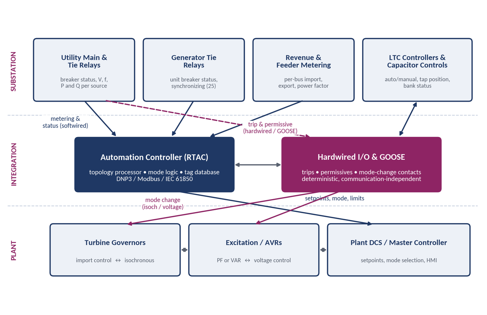
By SANDIP R PATEL
•
September 20, 2026
Learn CHP load following and island detection engineering for campus plants, including protection, controls, power studies, and grid transition design.
By SANDIP R PATEL
•
September 20, 2026
NERC MOD-025-2 Generator Owners, MOD-025-2 reactive power testing, generator capability verification, NERC Attachment 1, MOD-025 compliance testing
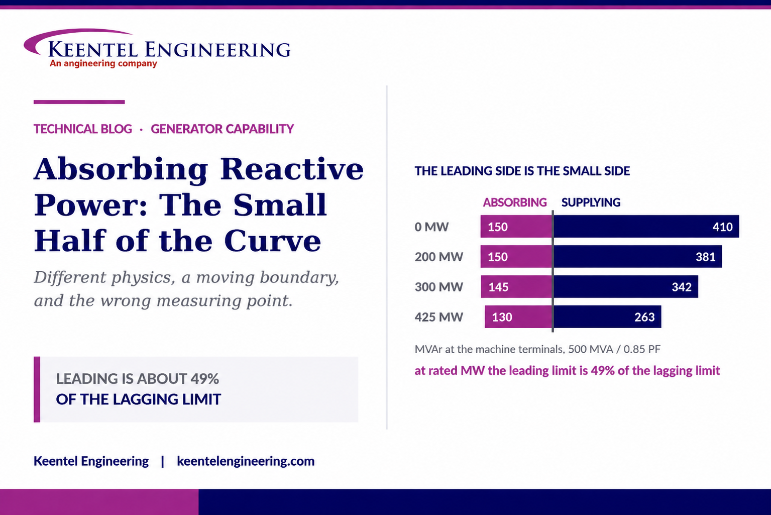
By SANDIP R PATEL
•
September 20, 2026
Understand generator capability curves, reactive power absorption, MVAr limits, MOD-025 verification, protection coordination, and grid requirements.
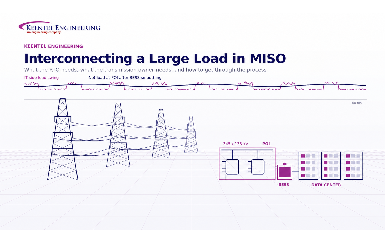
By SANDIP R PATEL
•
September 20, 2026
Understand MISO large load interconnection requirements for data centers, including TO data, PSS®E models, ride-through, harmonics, BESS and EPR.
By SANDIP R PATEL
•
September 19, 2026
Explore utility scale solar engineering from site assessment to POI interconnection, including PV design, BESS, substation and grid studies.
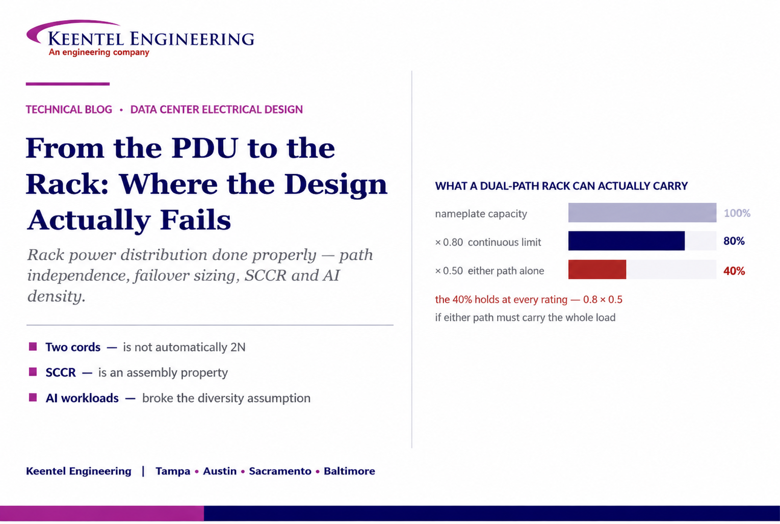
By SANDIP R PATEL
•
September 18, 2026
Learn how to size rack power distribution, PDU and RPP systems for continuous loads, A/B redundancy, failover capacity, SCCR and high-density AI data centers.
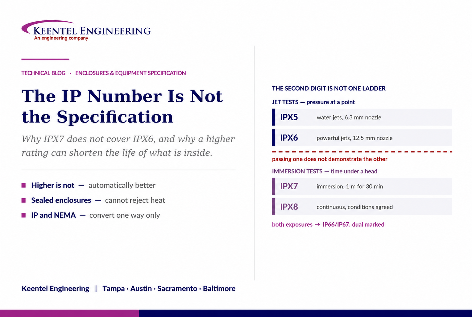
By SANDIP R PATEL
•
September 18, 2026
Learn why IP ratings like IP66, IP67, and IP68 do not tell the full story. Understand enclosure selection, NEMA differences, heat, corrosion, and protection.





