Part A — RMU vs. MV Switchgear for a 10 MW Data Center at a Glance
Every data center owner eventually faces the same medium-voltage (MV) question: should the 13.8 kV distribution be built from compact ring main units, from conventional metal-clad switchgear, or from a combination of the two? The answer shapes reliability, maintainability, arc-flash exposure, expansion cost and footprint for the life of the facility.
This guide works through that decision for a representative US facility: 10 MW of IT load, served at 13.8 kV, 60 Hz, with transformation to 480Y/277 V. It translates the European "ring main unit" concept into US equipment categories and standards, sizes the transformers and switchgear properly, checks the redundancy claims that are often made too casually, and shows when each option is the right engineering answer.
The facility in this guide
| Item | Value used by Keentel |
|---|---|
| IT load (UPS output) | 10 MW |
| Annualized PUE | 1.20 |
| Annualized average facility load | 10 MW × 1.20 = 12 MW |
| Design-day peak facility load (hot day, full mechanical) | about 13.5 MW (peak PUE about 1.35) |
| Utility service | 13.8 kV, two feeders, 60 Hz |
| Assumed power factor | 0.95 lagging |
| Utility available fault duty at the service point | 500 MVA three-phase (about 20.9 kA) |
| Secondary voltage | 480Y/277 V (US practice — not 400 V) |
| Unit substation transformers | 2,500 kVA, 13.8 kV delta – 480Y/277 V, 5.75% impedance |
What Keentel's analysis shows
| Check | Result | What it means |
|---|---|---|
| Facility current at 12 MW, 0.95 PF | 12,000 ÷ (√3 × 13.8 × 0.95) = 528 A | Arithmetic is correct, but it is an operating current, not a rating basis |
| Apparent power at 12 MW | 12 ÷ 0.95 = 12.63 MVA | This is the number transformers and switchgear must carry |
| Current at design-day peak (13.5 MW) | 595 A | Use peak, not annualized PUE, for equipment sizing |
| Current with 25% growth on 12.63 MVA | 15.79 MVA, 661 A | Incomer, main bus and tie: 1,200 A class minimum; 2,000 A if growth is uncertain |
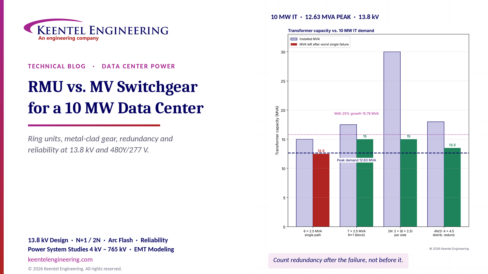
| Six 2,500 kVA transformers | 15 MVA installed, 84% loaded at 12.63 MVA | Enough for N, but not N+1 — losing one leaves 12.5 MVA, less than 12.63 MVA |
| N+1 (block redundant) with 2,500 kVA units | Seven units, 17.5 MVA | Survives one transformer failure at 84% loading |
| 2N with 2,500 kVA units | Two sides of six units, 30 MVA | Each side carries the full load; normal loading 42% |
| Utility fault duty at 13.8 kV | 500 MVA → 20.9 kA | 25 kA class equipment is the minimum; 40 kA if the utility or an owner substation can grow |
| Secondary bolted fault, 2,500 kVA, 5.75% | about 48 kA at 480 V (52 kA on an infinite source) | Drives LV switchboard and breaker ratings and arc-flash energy |
| MV-path unavailability (illustrative, excluding UPS and generators) | Radial 4.7 h/yr; single-source open ring 4.8 h/yr; main-tie-main 2.2 h/yr; 2N 0.17 h/yr | A ring with one source is no more reliable than a radial feed from the same source |

Figure 1. Keentel analysis for the 10 MW facility. Left: installed transformer capacity and the capacity remaining after the worst single transformer failure, against the 12.63 MVA peak demand and a 25% growth allowance. Right: illustrative unavailability of the MV path to a 480 V bus for four topologies, using failure-rate and repair-time values in the range of published industry survey data; generators and UPS are excluded so that the MV architecture can be compared on its own.
Five lessons
Compact ring switchgear and metal-clad switchgear are not competitors; they do different jobs. Metal-clad drawout breaker switchgear is the right tool for the main 13.8 kV bus, where incomers, ties, generator paralleling and relay-based protection meet. Compact load-interrupter or fault-interrupter switchgear is the right tool at the transformer, where it saves space and cost.
Count redundancy after the failure, not before it. Six 2.5 MVA transformers carrying 12.63 MVA cannot lose one. A design is N+1 only if the remaining capacity, after the worst single failure, still carries peak load — and only if the load can actually be transferred to it.
A ring is only redundant if it has two sources. An open loop fed from one utility circuit protects against cable faults, but not against loss of that circuit. Two "independent" utility feeders from the same substation bus share a common-mode failure.
Design to US practice. In the US, the secondary is 480Y/277 V, the equipment standards are IEEE C37 and UL, and the installation rules are the NEC and NFPA 70E — not IEC 62271 and 400 V.
Transformer repair time dominates. In the reliability model, a failed 2.5 MVA transformer that takes weeks to replace contributes more downtime than every switch and breaker combined. Secondary-selective arrangements, 2N paths or an on-site spare matter more than the MV switch type.
Engineering review of common statements about RMUs and MV switchgear
| Common statement | Keentel's check |
|---|---|
| "Current = 12,000 kW ÷ (√3 × 13.8 kV × 0.95) ≈ 529 A" | Correct (528.5 A). But it is based on annualized PUE. Equipment must be sized for design-day peak (hot weather, full cooling), UPS recharge, transformer losses and growth: in this guide about 595 A at peak and 661 A with 25% growth. The incomer, main bus and tie are 1,200 A class at minimum. |
| "Six 2.5 MVA transformers = 15 MVA; at 0.95 PF this is 14.25 MW (apparent power)" | Mislabeled. 15 MVA is the apparent power; 14.25 MW is the real-power equivalent at 0.95 PF. And the useful test is not total capacity but capacity after a failure: 12.5 MVA remains, which is less than the 12.63 MVA load. |
| "Utility supply feeds an MV ring connecting several transformer substations" | Accurate as a description, but a ring fed from a single source has the same exposure to loss of that source as a radial feed. To be redundant, the ring must close back to a second, independent source or bus section, and the switching must be fast enough for the load. |
| "Two incoming utility feeders, separate bus sections and a bus coupler" | A sound US main-tie-main arrangement. Its value depends on how independent the two feeders really are (same substation transformer, same bus, same right-of-way?) and on the transfer scheme. |
| "Transformer substations to LV 0.4 kV" | Not US practice. US data centers use 480Y/277 V for UPS, mechanical and distribution; 415Y/240 V appears downstream for IT power distribution. |
| "Applicable IEC standards" | In the US, apply IEEE C37.20.2 (metal-clad), C37.20.3 and C37.20.9 (metal-enclosed), C37.74 (pad-mounted fault interrupters and switches), C37.04/C37.06/C37.09 (breakers), C37.60 (fault interrupters), UL listings, NEC (NFPA 70) and NFPA 70E/70B. |
| "Some RMUs use fused switches, others circuit breakers" | Correct, and it is the key protection decision. A fused switch has no relay, no remote trip on transformer alarms and risks single-phasing; a vacuum fault interrupter or breaker with a relay gives three-phase tripping, ground-fault detection and coordination flexibility. |
| "Conventional MV switchgear requires more space and cost" | Usually true per position, but compare complete systems: switchgear lineup, house or skid, relaying, arc-resistant construction, maintenance access and future positions. |
Part B — Ring Main Units vs. Metal-Clad MV Switchgear for a 10 MW Data Center: A US Engineering Guide
1. Why the MV architecture decision matters
A 10 MW IT facility is large enough that its MV system is a real power system: two utility services, several unit substations, generators that may be paralleled at 13.8 kV or at 480 V, and protective relaying that must coordinate with the utility. It is also small enough that owners are tempted to treat MV equipment as a commodity and choose on first cost and footprint.
That temptation is where problems start. The MV architecture fixes:
how many single points of failure stand between the utility and each UPS input;
whether equipment can be maintained without shutting down critical load (concurrent maintainability);
the arc-flash incident energy on every MV and 480 V switchboard;
how fast a failed transformer or cable can be isolated and its load restored;
how easily the site grows from 10 MW to 15 or 20 MW.
Compact ring main units and conventional metal-clad switchgear answer these questions differently. The right answer is usually a combination, but only after the load, redundancy target and utility service are understood.
2. Equipment categories in US terms
The term "ring main unit" comes from European and IEC practice, where compact gas-insulated switching assemblies (typically two ring switches plus one transformer tee) are standard in urban distribution. In the US, the same functions are delivered by several equipment categories, each with its own IEEE standard.
| US equipment category | Typical construction | Switching device | Governing standards | Typical data center use |
|---|---|---|---|---|
| Metal-clad switchgear | Drawout vacuum breakers in grounded metal compartments, separate compartments for breaker, bus, cables and instruments | Vacuum circuit breaker with relay | IEEE C37.20.2; breakers to C37.04, C37.06, C37.09; application to C37.010 | Main 13.8 kV bus: utility incomers, ties, generator breakers, feeder breakers |
| Metal-enclosed interrupter switchgear | Fixed-mounted load-interrupter switches, often with power fuses | Load-break switch, fused switch | IEEE C37.20.3; switches to C37.20.4 | Transformer primary switching, small sites |
| Metal-enclosed breaker or vacuum-interrupter switchgear (compact) | Fixed or drawout, often gas- or solid-insulated | Vacuum breaker or vacuum fault interrupter with relay | IEEE C37.20.9 (metal-enclosed switchgear rated above 1 kV), C37.60 | Compact distribution lineups, ring and loop switching |
| Pad-mounted switchgear | Outdoor, tamper-resistant, air-, oil-, solid- or gas-insulated | Load-break switches, fuses, vacuum fault interrupters | IEEE C37.74 (pad-mounted, vault-mounted and submersible switchgear up to 38 kV), C37.60 | Campus loops, utility-style service, transformer taps |
| Unit substation primary section | Close-coupled to the transformer | Fused load-interrupter or vacuum breaker | IEEE C37.20.3 or C37.20.2, C57.12 series for the transformer | The 13.8 kV – 480Y/277 V unit substation |
In this guide, "RMU" therefore means compact metal-enclosed or pad-mounted switchgear with ring (loop) switches and a transformer tee, whether the tee is a fused switch, a vacuum fault interrupter or a compact breaker. "Conventional MV switchgear" means metal-clad, drawout vacuum breaker switchgear with relays.
2.1 What actually differs
| Attribute | Metal-clad drawout switchgear | Compact ring / pad-mounted switchgear |
|---|---|---|
| Interrupting device | Circuit breaker with full fault-interrupting rating and relay | Load-break switch (no fault interruption), fuse, or vacuum fault interrupter |
| Protection | Microprocessor relays: 50/51, 50N/51N, 87, 27/59, 81, 25, 67, breaker failure | Fuse curve, or electronic control on the fault interrupter; some compact units accept relays |
| Maintainability | Breakers rack out for maintenance; spare breaker can be swapped in hours | Sealed tanks; a failed switch may mean replacing a module — days to weeks |
| Compartmentalization | Grounded barriers between breaker, bus and cable compartments | Less compartmentalization; gas tank is one shared space |
| Arc-resistant option | Available to IEEE C37.20.7 Type 2B | Available on many designs; check the rating and venting |
| Footprint per position | About 36 in. wide by 90–100 in. deep, plus rear access | About 15–24 in. per function, front access |
| Bus rating | 1,200 A, 2,000 A, 3,000 A | Typically 600 A or 630 A ring bus |
| Short-circuit rating | 25, 40, 50 kA classes | Commonly 16–25 kA |
| Generator paralleling and automatic transfer | Natural fit | Possible only with motorized switches and external logic; limited |
| Insulating medium | Air with vacuum interrupters | Air, solid dielectric, oil, SF6 or SF6-free gas mixtures |
The 600–630 A ring-bus rating of most compact units is the first clue about where they belong. At 13.8 kV, 630 A carries about 15 MVA. That is enough for a transformer loop, but not much margin for the main bus of a growing 12.6 MVA facility.
3. Understanding the electrical load properly
3.1 From IT load to facility demand
The facility load starts with the IT load and the power usage effectiveness:

With 10 MW of IT and an annualized PUE of 1.20, the facility average is 12 MW. That figure is correct for energy, but not for sizing. Annualized PUE averages cool and hot days. On the design day, chillers or dry coolers work hardest, and peak PUE is often 1.30–1.45 even in an efficient facility. Keentel uses 1.35 in this example:

UPS losses and battery recharge add load on the input side of the UPS. A double-conversion UPS at 96% efficiency draws about 10.4 MW to deliver 10 MW, and recharge after a discharge can add 5–10% of UPS rating for a period. Some of this is captured in PUE; check that it is not double counted, but do not ignore it.
3.2 Apparent power and current
Transformers and switchgear are rated in kVA and amperes, so convert real power with the power factor:


Worked example 1 — facility current.
| Basis | P (MW) | S at 0.95 PF (MVA) | I at 13.8 kV (A) |
|---|---|---|---|
| Annualized average (PUE 1.20) | 12.0 | 12.63 | 528 |
| Design-day peak (PUE 1.35) | 13.5 | 14.21 | 595 |
| Annualized average + 25% growth | 15.0 | 15.79 | 661 |
The common estimate of 529 A is arithmetically right. It is the starting point, not the rating. Modern UPS rectifiers and IT power supplies often operate near unity power factor, while mechanical loads with variable-frequency drives are also near unity at the fundamental; 0.95 is a reasonable planning value, but harmonic currents still flow and must be considered in transformer and cable heating (Section 6.3).
3.3 Sizing the main bus, incomers and tie
In a main-tie-main arrangement, each main breaker must carry the entire facility when the other source is out, and the tie must carry the load of the dead side:

where g is the growth allowance. With 661 A including 25% growth, a 1,200 A main bus and 1,200 A mains and tie are the minimum. If the owner expects to add a second 10 MW phase on the same service, 2,000 A is the sensible choice: the incremental cost in metal-clad gear is modest, and replacing a bus later is a major outage.
A compact ring bus rated 630 A cannot be the main bus for this facility once growth is considered. That alone pushes the main distribution toward metal-clad switchgear.
4. The utility service and short-circuit duty
4.1 Service options
| Service arrangement | Description | Typical when |
|---|---|---|
| Single 13.8 kV feeder | One utility circuit | Not acceptable for a critical 10 MW facility |
| Two 13.8 kV feeders, same utility substation bus | Two breakers, one bus | Common; shared bus is a common-mode exposure |
| Two 13.8 kV feeders, different substation buses or transformers | Independent within the substation | Preferred utility distribution service |
| Two feeders from different substations | Geographically diverse | Best distribution-level independence; often costly |
| Owner 69, 115 or 138 kV substation with 13.8 kV secondary | Owner-operated transformers, often two | Usual above about 20–30 MW, or where distribution capacity is short |
For 10 MW, dual 13.8 kV feeders are the common service. Owners should ask the utility exactly where the two feeders separate: at different substation transformers, different buses, or merely different feeder breakers on the same bus. That answer decides whether the second feeder protects against a substation event.
4.2 Short-circuit duty at 13.8 kV
Worked example 2 — utility fault duty. The utility quotes 500 MVA three-phase available at the service point:

Metal-clad breakers rated 25 kA symmetrical would be adequate today, but the X/R ratio, motor contribution from large chiller motors, possible future utility system reinforcement and generator paralleling at 13.8 kV can all raise the duty. Many owners specify 40 kA for the main lineup to avoid a future rating problem. Compact ring units are commonly rated 16–25 kA; at 20.9 kA plus margin, their rating must be verified, not assumed.
Worked example 3 — owner substation. If the facility instead takes 138 kV service with its own transformer, the 13.8 kV fault level depends mainly on the transformer impedance. With 40 kA available at 138 kV:


| Transformer | Z | Through-fault MVA | Fault at 13.8 kV |
|---|---|---|---|
| 30 MVA (base rating) | 10% | 291 MVA | 12.2 kA |
| 50 MVA (base rating) | 8% | 587 MVA | 24.5 kA |
The larger, lower-impedance transformer pushes the 13.8 kV bus to 24.5 kA — beyond a 25 kA rating once motor contribution is added. Transformer impedance, switchgear rating and future growth must be selected together.
4.3 X/R ratio and asymmetry
Breaker ratings under IEEE C37.04/C37.06 assume a standard DC time constant (45 ms, roughly X/R = 17 at 60 Hz). Where the system X/R is higher — close to large transformers or generators — the asymmetrical current at contact parting rises, and IEEE C37.010 methods must be used to check the breaker. Compact switchgear and fault interrupters have their own test-duty assumptions under C37.60 and C37.74; confirm the X/R basis in the rating.
5. Topologies for a 10 MW facility
5.1 Radial
One source, one path to each transformer. Simple and cheap, but every component is a single point of failure. Not acceptable as the only path for a critical 10 MW facility, although radial feeders downstream of a redundant main bus are normal.
5.2 Loop (ring), open point
Transformers are connected in a loop with an open switch somewhere in it. A cable fault is isolated by opening switches on either side and closing the open point; all transformers are then re-energized. This is where ring switchgear excels.
But a loop fed from one source has no protection against loss of that source. To be redundant at the source, the loop must be fed from two sources — two utility feeders, or two bus sections of the main switchgear — with the normally open point between them.
5.3 Primary-selective
Each transformer has two MV supplies (A and B) with a selector switch or two interlocked switches. Loss of one MV feeder is covered by transferring to the other. This can be built from compact switchgear with motorized switches or from metal-clad breakers.
5.4 Secondary-selective (double-ended unit substations)
Two transformers, each fed from a different MV bus, supply two 480 V buses joined by a normally open tie. If one transformer or its MV source fails, the 480 V tie closes. This is the backbone of many data center designs because it protects against the longest outage — transformer failure — and allows transformer maintenance without load loss.
5.5 Main-tie-main at 13.8 kV
Two utility incomers, two bus sections and a normally open tie, with automatic transfer. This is the conventional switchgear arrangement and the natural point of connection for 13.8 kV generators.
5.6 Data center redundancy architectures
| Architecture | Concept | MV implication |
|---|---|---|
| N | Just enough capacity | Any failure drops load |
| N+1 (block redundant) | One extra block with a means to transfer to it (reserve bus or catcher) | Requires transfer switching or a reserve bus |
| 2N | Two complete, independent paths, each able to carry the whole load | Two MV buses, two sets of transformers, dual-corded IT |
| Distributed redundant (for example 4N/3) | Several systems each loaded to a fraction; loss of one shifts load to the others through static transfer or dual cords | More, smaller transformers; careful load assignment |
| 2(N+1) | Two paths, each with internal redundancy | Highest cost; used for the most critical facilities |
Keentel's related guide on data center tier classification explains how these architectures map to concurrent maintainability and fault tolerance. The MV system must support the chosen architecture: an elegant 2N UPS design fed from a single-source ring is not 2N at the facility level.
6. Transformer sizing and loading
6.1 Why six 2.5 MVA units are not N+1
Worked example 4 — counting redundancy. The facility peak apparent power is 12.63 MVA (annualized basis). Test each option after the worst single transformer failure:

| Option | Installed | After one failure | Covers 12.63 MVA? | Normal loading |
|---|---|---|---|---|
| 6 × 2,500 kVA, single path | 15.0 MVA | 12.5 MVA | No (99% of need) | 84% |
| 7 × 2,500 kVA, N+1 block redundant | 17.5 MVA | 15.0 MVA | Yes | 72% |
| 6 × 3,000 kVA (N = 5, plus 1) | 18.0 MVA | 15.0 MVA | Yes | 70% |
| 2N: two sides of 6 × 2,500 kVA | 30.0 MVA | 15.0 MVA per side | Yes, either side alone | 42% |
| 4N/3 distributed redundant, 4 × 4,500 kVA | 18.0 MVA | 13.5 MVA | Yes | 70% |
Two caveats apply. First, N+1 only works if the load of a failed transformer can be transferred — through a 480 V tie, a reserve bus or dual-corded IT. Adding a seventh transformer that cannot pick up anyone's load adds nothing. Second, the check above uses annualized load; at design-day peak (14.21 MVA), the six-transformer case is short by 1.7 MVA after a single failure, and the 4N/3 case keeps only about 0.7 MVA of margin.
6.2 Transformer loading guidance
Liquid-filled transformers are designed to IEEE C57.12.00 and loaded under IEEE C57.91; dry-type transformers to C57.12.01 and C57.96. Both permit operation above nameplate for limited periods at the cost of insulation life. In data centers, Keentel typically:
sizes so that normal loading is at or below about 80% of the base (self-cooled) rating, leaving the fan-cooled rating for failure contingencies;
checks the contingency case (one transformer out) against the fan-cooled rating at the design ambient;
uses temperature-rise ratings (55/65 °C liquid; 80, 115 or 150 °C dry) deliberately — a lower-rise dry transformer has more overload capacity.
6.3 Harmonics and K-factor
UPS rectifiers with active front ends draw low-distortion current, but legacy six-pulse rectifiers, VFDs and IT power supplies still produce harmonics. Harmonic current increases eddy-current losses in proportion to the square of harmonic order. The K-factor quantifies the effect:

where I(h,pu) is the harmonic current at order h divided by the rms load current. A transformer feeding modern active-front-end UPS modules may need only K-4; one feeding older six-pulse equipment or many VFDs may need K-13 or a derating calculated per IEEE C57.110. IEEE 519 sets the limits at the point of common coupling with the utility.
6.4 Transformer currents and secondary fault duty
Worked example 5 — a 2,500 kVA, 13.8 kV – 480Y/277 V unit substation.


On an infinite source with 5.75% impedance:

Including the 500 MVA utility source (0.5% on the 2.5 MVA base):

Reflected to the 13.8 kV side, that secondary fault is only about 1,670 A — roughly 16 times primary full-load current. This matters for protection: a primary fuse or relay must see this through-fault and clear it in time to protect the transformer, yet ride through magnetizing inrush that can be 8–12 times full-load current for about 0.1 s.
7. Transformer protection: fuse, fault interrupter or breaker
The protection device at each transformer is the single most important difference between "RMU" variants, and between compact switchgear and metal-clad switchgear.
7.1 NEC limits for transformers over 1,000 V
NEC 450.3(A) and Table 450.3(A) set the maximum primary and secondary overcurrent protection for transformers over 1,000 V. For a transformer with impedance not more than 6%, in any location, the primary may be protected by a circuit breaker set at up to 600% of rated primary current or a fuse rated up to 300%. Where conditions of maintenance and supervision ensure only qualified persons service the installation, the table permits a different set of limits (for example 300% breaker or 250% fuse on the primary when secondary protection is also provided). Always confirm against the edition of the NEC adopted locally.
Worked example 6 — NEC limits for the 2,500 kVA unit. Primary full-load current is 104.6 A.
| Device (primary, Z ≤ 6%, any location) | NEC maximum | Value |
|---|---|---|
| Circuit breaker | 600% | 628 A |
| Fuse | 300% | 314 A |
| Magnetizing inrush (planning value) | 12 × FLA for 0.1 s | 1,255 A |
| Secondary bolted fault reflected to primary | — | about 1,670 A |
A 13.8 kV power fuse sized around 150E–200E satisfies the NEC maximum and typically rides through inrush. The question is whether it protects the transformer against through-faults and coordinates with the 480 V main breaker.
7.2 Through-fault protection
IEEE C57.109 (liquid-immersed) and C57.12.59 (dry-type) define through-fault capability curves. A 2,500 kVA unit falls in Category III, where the damage curve has a frequent-fault portion that depends on impedance. The primary device must lie to the left of (faster than) the damage curve, adjusted for the delta-wye connection: a single-line-to-ground fault on the 480 V wye secondary appears on the delta primary as only 58% of the per-unit current in the faulted phases. Keentel shifts the damage curve by this factor before checking protection.
7.3 Fuse limitations
| Issue | Consequence |
|---|---|
| Single-phasing | One fuse blows; the transformer and downstream motors run on two phases. Motors overheat; UPS rectifiers may trip or see unbalance |
| No relay inputs | Transformer sudden-pressure, temperature or gas alarms cannot trip the fuse |
| Fixed curve | Coordination with the 480 V main is a compromise; ground-fault sensitivity on the primary is poor |
| Replacement | A blown fuse must be replaced manually under switching procedures, extending restoration |
| Arc-flash | Fuse clearing time at low secondary arcing currents can be long, increasing 480 V incident energy unless secondary protection is fast |
7.4 Vacuum fault interrupters and breakers
A vacuum fault interrupter (VFI) in pad-mounted or compact switchgear trips all three phases from an electronic control with selectable time-current curves and ground-fault settings. It removes the single-phasing risk and allows transformer alarms to trip. A metal-clad breaker with a relay goes further: 50/51 and 50N/51N, transformer differential (87T) on larger units, breaker failure, communications and event records.
| Function | Fused switch | VFI with electronic control | Metal-clad breaker + relay |
|---|---|---|---|
| Three-phase tripping | No | Yes | Yes |
| Ground-fault element | No | Yes | Yes |
| Accepts transformer trips (63, 26, 71) | No | Often, through auxiliary input | Yes |
| 87T differential | No | Rarely | Yes |
| Event records and communications | No | Limited | Full |
| Interrupting rating | Fuse rating | Typically 12.5–25 kA | 25–63 kA |
| Remote operation | Motor operator option | Yes | Yes |
| Approximate relative cost per position | Low | Medium | High |
For a 10 MW data center, Keentel generally recommends VFIs or breakers at transformer primaries. The cost difference over fused switches is small against the consequence of single-phasing a UPS input.
7.5 Coordination
Coordination studies should be performed with the full 13.8 kV and 480 V system: utility relay, 13.8 kV main and feeder relays, transformer primary device, 480 V main and feeder breakers, UPS input breakers and generator protection. IEEE 242 (Buff Book) gives coordinating time intervals; with modern relays and vacuum breakers, 0.2–0.3 s between relay curves is typical. NEC 700.32 and 701.32 require selective coordination for emergency and legally required standby systems, and NEC 645 and 708 add requirements in some facilities. Selective coordination of the data center's critical (non-emergency) load is usually an owner requirement rather than a code requirement, but it should be specified explicitly.
8. Arc-flash and worker safety
8.1 Incident energy at MV and 480 V
IEEE 1584-2018 calculates arc-flash incident energy for systems from 208 V to 15 kV. At 13.8 kV, incident energy is driven mainly by clearing time; at 480 V downstream of a 2,500 kVA transformer, by arcing current and the clearing time of the transformer primary device for faults on the transformer secondary terminals and 480 V main.
The weak point in most unit substations is the 480 V main breaker line side: a fault there is cleared only by the transformer primary protection. A fuse sized for inrush may take a second or more at the arcing current, producing tens of cal/cm².
Worked example 7 — clearing-time sensitivity. Incident energy is roughly proportional to arcing time. If a 480 V arc between the transformer and the 480 V main produces 5 cal/cm² per 0.1 s at 18 in., then:
| Clearing device for that zone | Clearing time | Approximate incident energy |
|---|---|---|
| Primary fuse, low arcing current | 1.0 s | about 50 cal/cm² |
| Primary relay 51 with instantaneous blocked | 0.5 s | about 25 cal/cm² |
| Transformer differential or arc-flash relay tripping primary breaker | 0.08 s | about 4 cal/cm² |
Values are illustrative; a full IEEE 1584 study with electrode configuration, enclosure size and gap is required.
8.2 Arc energy reduction
NEC 240.87 requires arc energy reduction for 480 V circuit breakers rated or adjustable to 1,200 A or more: zone-selective interlocking, differential relaying, an energy-reducing maintenance switch, an active arc-flash mitigation system, an instantaneous trip setting below the available arcing current, or another approved method. NEC 240.67 has a similar requirement for fuses rated 1,200 A or more. The 2,500 kVA transformer's 3,000 A secondary main is squarely in scope. The MV choice influences how easily this is achieved: a relay-controlled primary breaker can be tripped by an arc-flash light sensor or differential scheme, while a fuse cannot.
8.3 Arc-resistant construction
IEEE C37.20.7 defines arc-resistant switchgear testing. Type 2B accessibility protects personnel at the front, back and sides even with low-voltage compartment doors open. Arc-resistant metal-clad switchgear is now common in data centers, but it requires arc-exhaust plenums or a room designed for the pressure and gases. Compact gas-insulated switchgear also offers internal-arc classifications; check that the test conditions (current, duration, accessibility) match the installation.
8.4 NFPA 70E and 70B
NFPA 70E sets work practices: energized work permits, approach boundaries, PPE and the electrically safe work condition. NFPA 70B, issued in 2023 as a standard rather than a recommended practice, requires an electrical maintenance program with condition assessments and maintenance intervals. Drawout breakers, test positions and remote racking make 70B maintenance far easier to perform without exposure; sealed compact units need less maintenance but are harder to diagnose and repair.
9. Automatic transfer and source management
9.1 Main-tie-main logic
In the usual 13.8 kV main-tie-main arrangement, both mains are closed and the tie is open. On loss of voltage on one incomer (27 undervoltage with a time delay to ride through utility reclosing), the scheme opens that main and closes the tie, after checking that the dead bus has decayed (or that the sources are synchronized). When the utility returns and is stable for a set time, the scheme retransfers.
| Design choice | Options | Considerations |
|---|---|---|
| Transfer type | Open transition (break-before-make) | Short interruption; UPS rides through on battery |
| Closed transition (make-before-break, < 100 ms paralleling) | Needs utility approval, sync check (25) and interconnection protection | |
| Dead-bus check | Residual voltage below about 25–30% before closing | Prevents out-of-phase closing on motor back-EMF |
| Time delays | Ride through utility reclosing (often 0.5–2 s) | Coordinate with UPS battery and generator start |
| Fault lockout | Block transfer if the main tripped on overcurrent | Never transfer onto a faulted bus |
Compact ring switchgear with motorized switches can perform loop restoration (fault location, isolation and service restoration), but it is generally slower and less flexible than a relay-based main-tie-main scheme. If the transfer must happen within seconds and coordinate with generators, metal-clad switchgear is the natural platform.
9.2 Generators at 13.8 kV or at 480 V
| Approach | Advantages | Considerations |
|---|---|---|
| 480 V generators per unit substation (one or two per transformer) | Simple; failure isolated to one block | Many generators; more ATSs; harder to share capacity |
| 13.8 kV paralleling switchgear with medium-voltage generators | Pooled capacity; N+1 at the generator level; fewer, larger units | Requires metal-clad switchgear, 25 sync, 32 reverse power, 87G, 40 loss of field, generator grounding |
| 480 V generators with step-up transformers to 13.8 kV | Lower-cost generators | More transformers; grounding and protection complexity |
For a 10 MW facility, paralleled 13.8 kV generators (for example six 2.5 MW units with one redundant) are attractive. That decision effectively mandates metal-clad switchgear for the main bus.
9.3 UPS placement
UPS systems are almost always at 480 V in a 10 MW facility, downstream of the unit substations. MV UPS systems exist, but are typically justified at larger scales. The MV system's job is to deliver two independent, maintainable sources to the UPS inputs. If the IT is dual-corded, the UPS architecture (2N, distributed redundant or block redundant) sets the minimum MV requirement.
10. Insulation media and environmental rules
Many compact switchgear designs use SF6 gas. SF6 is an excellent insulating and interrupting medium, but it has a global warming potential about 23,500 times that of CO2 (100-year basis) and an atmospheric life of thousands of years.
The US EPA Greenhouse Gas Reporting Program (40 CFR Part 98, Subpart DD) requires reporting of SF6 emissions from electric power systems above a threshold of nameplate capacity.
California's regulation on gas-insulated equipment (California Code of Regulations, Title 17) phases out the purchase of new SF6 equipment, starting with lower voltage classes such as distribution-class equipment, and sets annual emission limits. Several other states, including Massachusetts, New York and Washington, have SF6 or high-GWP gas rules.
Owners should confirm the current rules for their state before specifying SF6 equipment. SF6-free alternatives — vacuum interrupters with dry air, solid dielectric or alternative gas mixtures — are increasingly available in compact 15 kV equipment. Metal-clad switchgear uses vacuum interrupters in air and avoids the issue entirely.
11. Reliability: putting numbers on the architecture
11.1 Method
IEEE 493 (the Gold Book) gives a practical method for comparing configurations: represent each component by a failure rate λ (failures per year) and a mean repair or restoration time r (hours), then combine them.
For components in series (all must work):


For two redundant paths in parallel (either is enough), with r in hours:


Unavailability U is in hours per year; availability is:

11.2 Illustrative component data
The values below are illustrative and lie in the range of published survey data; a real study uses the owner's and utility's data and current editions of the survey tables.
| Component | λ (failures/yr) | r (h) | Comment |
|---|---|---|---|
| Single 13.8 kV utility circuit | 1.956 | 1.32 | Commonly cited single-circuit utility value |
| Loss of both utility circuits (common mode) | 0.312 | 0.52 | Captures shared substation and weather events |
| Metal-clad breaker | 0.004 | 8 | Drawout; spare breaker swapped |
| 13.8 kV bus section | 0.002 | 26 | |
| MV cable run | 0.006 | 24 | Repair; 1 h if restorable by loop switching |
| Load-break switch in sealed compact unit | 0.003 | 48 | Module replacement |
| Power fuse | 0.002 | 2 | Replace fuse |
| 2,500 kVA transformer | 0.006 | 300 | Replacement from spare or stock |
| 480 V main breaker | 0.003 | 8 |
11.3 Results
Worked example 8 — four MV architectures to one 480 V bus.
| Architecture | λ (per yr) | Mean outage (h) | U (h/yr) | Availability |
|---|---|---|---|---|
| Radial, single utility feeder | 1.98 | 2.4 | 4.67 | 0.99947 |
| Open ring from one utility feeder, fused tee | 1.98 | 2.4 | 4.85 | 0.99945 |
| Main-tie-main at 13.8 kV, radial transformer | 0.33 | 6.6 | 2.22 | 0.99975 |
| 2N: two complete paths to dual-corded load | 0.31 | 0.5 | 0.17 | 0.99998 |
Four conclusions follow:
The single-source ring is no better than radial. Its benefit — fast restoration after a cable fault — is swamped by the exposure to the one utility feeder. Rings need two sources.
Main-tie-main cuts outage frequency by a factor of six, because utility outages are covered by transfer. But the transformer and its radial feeder now dominate unavailability: 0.006 failures per year × 300 h = 1.8 h/yr of the 2.2 h/yr total.
2N removes the transformer from the critical path. What remains is the common-mode loss of both utility circuits, which is why source independence (Section 4.1) matters.
UPS and generators change the absolute numbers, not the ranking. Utility outages are carried by UPS batteries and generators; the MV path still determines how often the facility runs on its backup systems and how exposed it is when a transformer fails.
Availability expressed in "nines" can mislead. A design with 0.99998 availability and one long outage every decade is very different from one with frequent short events; use frequency and duration together.
12. Footprint, cost and schedule
The figures below are indicative ranges for planning in 2026 US dollars and vary with region, ratings and supply-chain conditions.
| Item | Metal-clad drawout switchgear | Compact ring / pad-mounted switchgear |
|---|---|---|
| Width per position | 36 in. | 15–24 in. per function |
| Depth and access | 90–100 in., front and rear access | 30–60 in., often front access only |
| Indicative installed cost per 15 kV position | $80,000–$200,000 including relays | $25,000–$80,000 per switching function |
| Typical lead time (2025–2026 market) | 40–80 weeks | 20–60 weeks |
| Enclosure | Indoor in an electrical room, or outdoor walk-in or skid | Outdoor pad-mounted or indoor compact |
| Expansion | Add sections if planned (bus extension provisions) | Add units to the loop; ring-bus rating limits growth |
Two cautions: lead times for MV switchgear and transformers have been long since 2022 and drive project schedules; and the cheapest switching device is not cheapest if it forces extra transformers, generators or space elsewhere.
13. The recommended architecture for this 10 MW facility
Keentel's typical recommendation for a 10 MW IT facility with dual 13.8 kV service is a hybrid:
| Level | Equipment | Arrangement |
|---|---|---|
| Utility service | Two 13.8 kV feeders from separate substation buses or transformers | Utility metering per feeder |
| Main distribution | 15 kV class metal-clad drawout vacuum breaker switchgear, 1,200 A or 2,000 A bus, 40 kA | Main-tie-main, A and B bus sections; generator paralleling section if MV generators are used |
| Transformer feeders | One metal-clad feeder breaker per path, with 50/51, 50N/51N and arc-flash tripping | A side feeds A transformers; B side feeds B transformers |
| Transformer primaries | Compact VFI or breaker switchgear at each unit substation | Primary-selective where two MV paths reach one transformer; otherwise radial from each bus |
| Transformers | 13.8 kV delta – 480Y/277 V, sized for the chosen redundancy (Section 6.1) | Double-ended unit substations with a 480 V tie, or 2N paths to dual-corded UPS |
| Mechanical loads | Separate 480 V substations from both buses | Sized for design-day peak |
This keeps the drawout breakers, relaying and transfer logic where the system's flexibility is needed — at the main bus — and uses compact equipment where footprint and cost matter and functions are simple.
Worked example 9 — a 2N layout with 2,500 kVA units. Each of the A and B sides has six 2,500 kVA transformers (15 MVA per side). Each side alone carries 12.63 MVA at 84%, and under normal 2N operation each transformer runs at about 42%. The 13.8 kV feeders: each of the twelve transformers draws 104.6 A at full rating, so a single 600 A feeder breaker could supply up to five units — but for maintainability, Keentel normally uses one feeder per one or two transformers. The main bus carries the full facility, 528–661 A, well within a 1,200 A rating.
If the owner prefers block-redundant (N+1) UPS to reduce cost, seven 2,500 kVA transformers with a 480 V reserve bus meet the requirement at 72% normal loading — provided the reserve can actually pick up any one block's load.
14. Expansion and phasing
Data centers rarely stop at the first phase. Practical steps:
Size the main bus for the ultimate service (2,000 A at 13.8 kV covers about 47 MVA thermally, but the utility service and short-circuit rating will limit first).
Install spare breaker cells or bus-extension provisions on both ends of the lineup.
Plan a second lineup and utility service rather than overloading the first; at 20–30 MW, an owner 69, 115 or 138 kV substation often becomes economic.
Keep spare duct-bank capacity to every future unit substation location.
Re-run short-circuit, coordination and arc-flash studies with each phase; fault duty grows as transformers and generators are added.
15. Testing and commissioning
Whatever equipment is chosen, the acceptance test program should follow the NETA Acceptance Testing Specifications and the manufacturer's instructions, and include:
insulation resistance and, for metal-clad equipment, power-frequency or VLF withstand of buses and cables;
breaker timing, contact resistance and vacuum integrity;
relay secondary injection against approved settings, and end-to-end trip testing to each breaker;
CT ratio, polarity and excitation; VT ratio and polarity;
transfer-scheme functional testing under every source-loss scenario, including generator integration;
fuse and VFI control verification on compact units, and gas-pressure checks where SF6 or other gas is used;
integrated systems testing (pull-the-plug) of the complete facility at load banks before IT load arrives.
16. Common misconceptions corrected
| Misconception | Correction |
|---|---|
| "529 A, so a 630 A ring bus is enough" | Size for peak, contingency and growth; 661 A with 25% growth exceeds a 630 A bus |
| "Six transformers give N+1" | Only if one can fail without exceeding the rest; at 12.63 MVA, six 2.5 MVA units cannot |
| "Two utility feeders mean 2N" | Only if they are independent and each path can carry the full load end to end |
| "A ring is redundant" | Only if it is fed from two sources |
| "Fused RMUs are as good as breakers" | Not for single-phasing, alarm tripping, ground faults or arc-flash mitigation |
| "IEC ratings are equivalent" | US installations need IEEE/ANSI-rated, UL-listed equipment and NEC compliance |
| "Annualized PUE sizes the service" | Design-day peak sizes the service; annualized PUE estimates energy |
17. Key takeaways
Use metal-clad drawout switchgear for the 13.8 kV main distribution of a 10 MW facility, especially with MV generators or growth plans.
Use compact ring, pad-mounted or metal-enclosed switchgear with VFIs or breakers at the transformers, where it saves space and cost.
Check redundancy after the failure, against design-day peak, and confirm the load can actually transfer.
Make sure every ring and every "dual" service has truly independent sources.
Translate to US practice: 480Y/277 V, IEEE C37 and C57, UL, NEC and NFPA 70E/70B.
Treat transformer replacement time as the dominant reliability risk and design around it.
18. How Keentel Engineering helps
Keentel Engineering designs and studies MV distribution for data centers and other critical facilities, from 13.8 kV and 34.5 kV services to owner substations at 69, 115, 138 and 230 kV.
| Service | Keentel scope | Outcome |
|---|---|---|
| Concept and architecture | Load development (IT, PUE, peak, growth), redundancy architecture, utility service options | An architecture that matches the availability target |
| Single-line and equipment specification | Metal-clad, metal-enclosed and pad-mounted switchgear, transformers, generators | Specifications that procurement and vendors can price |
| Utility coordination | Service requests, fault-duty data, protection interface, interconnection of generators | A service the utility will approve |
| Power system studies | Load flow, short-circuit, coordination, arc-flash (IEEE 1584), harmonics (IEEE 519), motor starting | Ratings, settings and labels you can trust |
| Reliability analysis | IEEE 493 availability modeling of competing designs | Decisions based on numbers, not habit |
| Protection and transfer schemes | Relay settings, main-tie-main and generator logic, arc energy reduction | Fast, selective and safe operation |
| Owner's engineer and commissioning support | Submittal review, FAT and SAT witness, integrated systems testing | Equipment that performs as designed |
| Substation design | Owner 69–230 kV substations for data center campuses | A path to 20, 50 and 100 MW |
Why clients choose Keentel Engineering
Power system depth applied to data centers: utility-grade protection, short-circuit and reliability engineering, not just building distribution.
Technology-neutral recommendations: we specify the equipment that fits the requirement, not a product line.
Numbers behind every decision: load, fault duty, coordination, arc-flash and availability are calculated, not assumed.
US standards fluency: IEEE, NEC, NFPA, UL and utility requirements applied correctly.
Licensed professional engineering: a Florida-registered firm with offices in Tampa, Austin, Sacramento and Baltimore, supporting projects nationwide.
Planning a data center MV system, or checking whether an existing design really delivers N+1 or 2N? Talk to Keentel Engineering at (813) 389-7871, contact@keentelengineering.com, or book a 15-minute scoping call at calendly.com/keentel-engineering/15min.
Part C — Case Studies
The following are illustrative composite scenarios based on conditions typical of US data center projects. They show how Keentel Engineering approaches MV architecture decisions; site details are generalized and figures are rounded.
Case Study 1 — The "N+1" that wasn't
Situation. A developer in the Southeast was finalizing design for a 10 MW IT colocation facility with dual 13.8 kV utility feeders. The concept single-line showed a compact gas-insulated ring of six units, each with a fused tee to a 2,500 kVA, 13.8 kV – 480Y/277 V transformer, and was described in marketing material as "N+1 at every level." The ring was fed from one utility feeder; the second feeder connected only to the far end of the ring through a normally open switch.
Analysis. Keentel developed the load from first principles: 10 MW IT at UPS output, UPS losses at 96% efficiency, a design-day peak PUE of 1.36 and 0.95 power factor. Peak demand was 14.3 MVA. Six 2,500 kVA transformers provided 15 MVA — 95% loaded at peak, and only 12.5 MVA after one transformer failure. The 630 A ring bus would carry 598 A at peak with no growth margin. Both utility feeders originated from the same substation bus. The fused tees meant a single blown fuse would single-phase a UPS input, and the transformer temperature and pressure alarms had no way to trip. The arc-flash study showed 38 cal/cm² at the 480 V main line side, because only the primary fuse cleared that zone.
Engineered solution. Keentel redesigned the system as a 15 kV, 1,200 A, 40 kA metal-clad main-tie-main lineup with two bus sections, each feeding a separate set of transformers. Eight 2,500 kVA double-ended unit substations (four pairs with 480 V ties) replaced the six single-ended units, giving secondary-selective operation. Compact vacuum fault interrupter switchgear was retained at each transformer primary for footprint, with transformer alarms wired to trip. The developer asked the utility to supply the second feeder from a different substation transformer, which the utility agreed to with a modest line extension. Arc energy reduction used a light-sensing relay on each unit substation tripping the upstream VFI.
Outcome. After any single transformer or feeder failure, the remaining capacity exceeds design-day peak. 480 V arc-flash energy at the main dropped from 38 to under 8 cal/cm². The design was accepted by the facility's prospective anchor tenant, whose reliability consultant had flagged the original ring as non-compliant with its fault-tolerance requirement.
Case Study 2 — Retrofitting a fused loop at an enterprise campus
Situation. A financial-services enterprise in the Mid-Atlantic operated a 6 MW IT data hall fed from a 13.8 kV campus loop of pad-mounted fused switches installed in the 1990s. The owner planned a 4 MW expansion and experienced two events in three years in which a single primary fuse operated, leaving a transformer energized on two phases. In one event, a chiller motor tripped on unbalance and a UPS transferred to battery.
Analysis. Keentel performed short-circuit, coordination and arc-flash studies and inspected the loop. Utility fault duty had risen to 23 kA after a substation upgrade, exceeding the 16 kA rating of several pad-mounted units. The fuses were sized correctly under NEC 450.3, but their curves did not coordinate with the 480 V main breakers for low-level secondary faults. An IEEE 493 model showed that the single campus utility feeder, not the loop, accounted for most expected outage hours.
Engineered solution. The pad-mounted fused switches were replaced with 25 kA vacuum fault interrupter pad-mounted switchgear with three-phase tripping and ground-fault elements. A second 13.8 kV utility service from another substation was added, landing on a new metal-clad main-tie-main lineup that now feeds both ends of the loop through breakers. The loop operates normally open at the midpoint, with motorized switches and automatic restoration logic. The 4 MW expansion was supplied from new double-ended unit substations on the A and B buses.
Outcome. Single-phasing events were eliminated, short-circuit ratings were brought into compliance, and the expansion was energized without an outage to the existing hall. The modeled MV-path unavailability fell by about 60%.
Case Study 3 — Choosing the voltage and switchgear for a growing AI campus
Situation. A developer in the Southwest planned a campus starting at 10 MW IT and growing to 60 MW over five years. The utility could provide two 13.8 kV feeders for phase 1 but indicated that later phases would need 138 kV service. The initial design proposed compact ring switchgear throughout, to minimize first cost.
Analysis. Keentel compared three paths: compact switchgear now and replacement later; metal-clad 13.8 kV switchgear now, transferred to an owner substation later; and an owner 138 kV substation from day one. Future short-circuit duty at 13.8 kV with two 50 MVA, 8% transformers in parallel would reach about 46 kA — beyond any compact equipment rating — so the design was changed to operate those transformers split, each on its own bus section (24.5 kA each). The study also showed that 13.8 kV generator paralleling would cut the number of generators by a third compared with 480 V units.
Engineered solution. Phase 1 used 15 kV, 2,000 A, 40 kA metal-clad switchgear arranged as a main-tie-main lineup, with provisions for two future 138 kV transformer incomers and a 13.8 kV generator paralleling section. Compact VFI switchgear served transformer primaries in each data hall block. The owner reserved land and right-of-way for the 138/13.8 kV substation, which Keentel designed for phase 2.
Outcome. Phase 1 was energized on dual 13.8 kV feeders. When the 138 kV substation came online, the utility feeders were re-landed as alternate sources without replacing any switchgear, and the campus scaled without rebuilding its MV backbone.