A Coordinated Electric System Interconnection Review—the utility’s deep-dive on technical and cost impacts of your project.
Challenge: Frequent false tripping using conventional electromechanical relays
Solution: SEL-487E integration with multi-terminal differential protection and dynamic inrush restraint
Result: 90% reduction in false trips, saving over $250,000 in downtime
The three operating regions you have to design to
| Device | Output vs voltage | Response | Best suited to | Main limitations |
|---|---|---|---|---|
| Mechanically switched capacitor or reactor | Proportional to voltage squared | Seconds; discrete steps; limited switching operations per day | Steady-state reactive supply, voltage profile, loss reduction | No dynamic capability; step voltage change on switching; capability collapses when most needed |
| Static var compensator | Capacitive branches proportional to voltage squared | A few cycles; continuously controllable | Continuous control where cost matters and deep voltage support is not the driver | Square-law capability loss; harmonic filters are part of the plant and interact with the network |
| STATCOM | Approximately proportional to voltage — constant current capability | One to two cycles closed loop; converter response faster still | Voltage stability margin, weak interconnections, fast disturbance recovery, flicker and unbalance compensation | Higher capital cost; converter losses; adds a converter and its control dynamics to the network |
| Synchronous condenser | Governed by machine capability and excitation | Excitation response in the hundreds of milliseconds; inherent inertial response instantaneous | System strength and inertia, short-circuit contribution, black start support | Rotating plant with maintenance and losses; slower controlled response than a converter |
| STATCOM with energy storage | Reactive as a STATCOM, plus real power within the storage rating | As STATCOM for reactive; real power limited by storage | Where a real power deficiency is part of the problem | Cost and complexity of the storage; different failure and maintenance profile |
| Stage | Keentel scope | Outcome |
|---|---|---|
| Screening | Series-compensation proximity, radial contingency review, UIF and short-circuit ratio screening, frequency scans | Early identification of which SSO types apply |
| Detailed studies | PSCAD/EMTDC EMT studies with vendor real-code models, impedance-based and frequency-scan analysis | Clear evidence of stability margins or risk |
| Model quality | EMT model review, benchmarking against positive-sequence models, model acceptance support | Models that system operators accept |
| Mitigation | Control retuning recommendations with vendors, SSDC and bypass logic requirements, protection and monitoring specifications | Practical, coordinated solutions |
| Interconnection support | SSR and SSO study reports for ISO and utility requirements, response to reviewer comments | Fewer delays in the interconnection process |
Resilience: designing CDUs to the facility Tier objective
Liquid cooling makes heat removal more critical, not less. Cold plates hold only seconds of thermal buffer. If TCS flow stops, processors throttle or shut down very quickly. Resilience design must therefore cover:
- Pump redundancy: N+1 pumps at minimum, with automatic changeover.
- CDU redundancy: N+1 CDUs on a common TCS header, or 2N CDUs serving A and B manifolds for fault-tolerant designs.
- Power to CDUs: dual-corded CDUs fed from A and B sources, with pumps and controls on UPS power so coolant keeps flowing through a utility failure and generator start. This is the liquid-cooling equivalent of continuous cooling.
- Facility water continuity: chilled water or condenser water must also continue, through thermal storage, UPS-backed pumps or a high enough FWS temperature that the TCS can coast on stored thermal mass for the transfer period.
- Concurrent maintainability: isolation valves so any CDU, pump, filter or manifold section can be serviced without stopping the others.
- Leak management: leak detection, drip trays, automatic isolation valves and procedures for fluid spills.
Electrical engineering considerations
CDUs and liquid-cooling plants are electrical loads with their own design requirements:
- Pump motors and VFDs. Large CDUs use variable-frequency drives on their pump motors. These introduce harmonic current that must be included in the facility's harmonic study and IEEE 519 evaluation.
- Critical mechanical load on UPS. Putting CDU pumps on UPS increases UPS and battery sizing. The mechanical UPS load must be included in redundancy and ride-through calculations.
- Feeder and protection design. Dual feeds, automatic transfer, selective coordination and arc-flash labelling apply to CDU power distribution just as they do to IT power.
- Generator transient response. CDU pumps restarting together after a transfer create motor inrush on the generators. Staged restarts and soft acceleration reduce the step load.
- Load dynamics. AI training loads can swing rapidly between high and low power. Cooling controls must track those swings without temperature overshoot, and electrical systems must handle both the IT and the cooling load changes.
Commissioning a liquid-cooled data hall
- Flush and clean the TCS piping and manifolds to the specified cleanliness, using high-purity flush water.
- Fill and vent with the specified coolant, verifying glycol concentration and chemistry.
- Pressure test for leaks at design and test pressures, including quick-disconnect fittings.
- Verify sensors and controls: flow meters, temperature sensors, pressure transmitters, leak detection and BMS points.
- Load test with heat load banks connected through the cold-plate interfaces or rack manifolds, across the operating range.
- Prove the heat balance on both loops at several load steps, and the approach temperature against the design.
- Test failure scenarios: pump failure, CDU failure, power transfer to generator, valve failure and loss of facility water, confirming temperatures stay within the IT vendor's limits.
How Keentel Engineering helps
Keentel Engineering supports data center owners, developers and EPCs with the electrical engineering that liquid-cooled facilities depend on, and coordinates with the mechanical engineer of record and cooling vendors on the integrated design.
SPP's New Rules for Data Centers and Other Large Loads: A Plain-English Guide to HILL Requirements

October 30, 2026 | Blog
Southwest Power Pool (SPP) is moving to treat very large electricity users — data centers, crypto mining sites and big industrial plants — much like power plants: they must be studied before they connect, and they must stay connected through grid disturbances. SPP calls them High Impact Large Loads (HILLs). This guide explains, in plain English, what SPP's draft HILL documents require and what that means for anyone planning a large load in SPP.
1. Why SPP Created HILL Rules
The short answer: a large load that drops off the grid all at once can hurt the grid as much as a power plant that trips.
For decades, utilities expected customers' equipment to trip during a disturbance. A few homes or a factory dropping off for a second did not matter. That changed with the arrival of loads of hundreds of megawatts — the size of a mid-size power plant — often clustered in the same area.
When a fault happens on a transmission line (for example, lightning or a tree contact), voltage across a wide area dips for a fraction of a second until protection clears it. Data center electronics sense that dip and, if set to protect themselves aggressively, switch to backup power or shut down. If many megawatts disappear at once:
- Frequency jumps up, because generators are suddenly producing more than is being used.
- Voltage can swing high, because lightly loaded lines push voltage up.
- Other equipment may then trip, which is how a small event turns into a large one.
SPP's draft ride-through document states this directly: there are no industry standards that require loads to ride through faults, yet uncontrolled tripping of large loads "may cause or exacerbate cascading outages." So SPP is creating load requirements modeled on what generators already have to meet.
2. What Counts as a HILL, and Who the Rules Apply To
A HILL is defined in the SPP Tariff; the ride-through document points to the Tariff rather than repeating the size threshold. In practice, the label covers very large, fast-growing loads such as data centers, crypto mining and large industrial facilities. Check the current SPP Tariff for the exact definition that applies to your project.
The study process sits under SPP Tariff Attachments AQ, AX, BA and BB and SPP's business practice BP 7850. The draft ride-through rules apply:
- To new requests: HILLs that submit through SPP's transmission service process, or that are supported by a High Impact Large Load Generating Facility, on or after the effective date of SPP Revision Request RR 696 (the date is still a placeholder in the draft).
- To earlier requests, more softly: HILLs that applied to their Transmission Owner before that date must make "reasonable efforts" to maximize ride-through within their equipment's capability and document those efforts if asked.
- To generation on the same site: solar, batteries, gas generators or synchronous condensers that share a Point of Interconnection (POI) with a HILL have their own ride-through rules (Section 6 below).
One important nuance: the rules can be limited to the power-electronic part of a site. SPP's example is a 50 MW facility with 45 MW of conventional industrial load and 5 MW of power-electronic load; the requirements would apply only to the 5 MW, if SPP's study shows that exemption does not harm reliability.
3. How SPP Studies a HILL: The Delivery Point Study
Every HILL goes through SPP's base studies; only sites on a weak part of the grid go on to the detailed EMT stage.
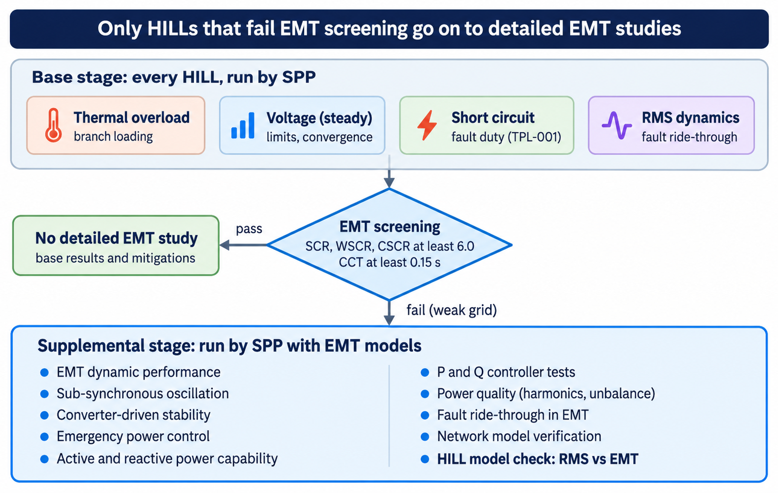
HILL Delivery Point Study · base and supplemental stages.
In the base stage SPP runs four studies with its full network model and your power-flow and RMS dynamic models, then screens
grid strength. A site that passes screening is judged on the base results and any mitigation they call for. A site that fails goes to the supplemental stage, where SPP uses detailed EMT models of both the grid and the HILL — so your PSCAD model must be ready and must agree with your PSS®E model.
4. Voltage Ride-Through, Explained
Ride-through means staying connected and keeping the load running while grid voltage briefly goes too low or too high. SPP's draft sets a minimum time a HILL must stay connected at each voltage level, measured at the POI (the point where the site meets the transmission system).
| Voltage at the POI (per unit of normal) | What it looks like | Must stay connected for at least |
|---|---|---|
| Above 1.20 | Severe overvoltage | Not required (may ride through or trip) |
| 1.10 to 1.20 | High voltage | 0.5 seconds |
| 0.90 to 1.10 | Normal range | Continuously — no tripping |
| 0.80 to 0.90 | Mild sag | 2.0 seconds |
| 0.50 to 0.80 | Moderate sag | 0.5 seconds |
| Below 0.50 | Deep sag, usually a nearby fault | 0.15 seconds (about 9 cycles) |
"Per unit" simply means a fraction of normal voltage: 0.80 per unit on a 345 kV line is about 276 kV.
Where the numbers come from. The table blends two familiar references. The first is the ITIC (formerly CBEMA) curve, the long-standing chart of how much voltage disturbance IT power supplies should tolerate. The second is ERCOT's July 2025 proposal for large electronic loads. SPP's appendix explains the logic:
- Below 0.5 pu for about 9 cycles (150 ms): loads close to a fault see deep sags, but most faults are cleared in 4 to 7 cycles, so loads should ride through normally cleared faults.
- 0.5 to 0.8 pu for 0.5 seconds: loads farther from the fault see shallower sags that can last up to 30 cycles when a fault is cleared by backup protection.
What the load should do during a moderate sag (0.5 to 0.8 pu). It should keep drawing power from the grid, reduced roughly in proportion to how far voltage has dropped. Briefly using less power actually helps the grid recover, which is why SPP allows it, but the load must stay connected.
5. Deep Sags, UPS Transfer and the 1-Second Recovery Rule
This is the requirement most likely to catch data center projects out. When voltage falls below about 0.5 pu, a server power supply's rectifier can no longer pull useful power from the grid. SPP accepts that, and gives the load two options:
- Transfer to UPS. The uninterruptible power supply carries the servers from its batteries while the grid is disturbed.
- Trip. The load may disconnect.
Either way, the load must come back to at least 90% of its pre- disturbance grid consumption within 1 second after voltage recovers to 0.9 pu or higher.
Why this matters: many UPS systems are set up to protect the computers, not the grid. After a sag they may stay on battery for several seconds, or ramp back slowly, to be sure the grid is stable. To the grid, a 250 MW data center that stays on battery for 10 or 15 seconds after every nearby fault looks the same as a 245 MW plant tripping offline. Under SPP's draft, that response would not meet the 1-second rule.
SPP allows one exception. In a weak grid, a fast snap-back can cause oscillations, so SPP and the Transmission Owner may agree to a longer recovery time. That is a negotiated exception, not a default.
What to do about it in practice:
- Ask your UPS manufacturer for the return-to-grid (re-transfer) time and ramp rate after a sag, and whether firmware settings can achieve 1 second.
- Make sure the dynamic model you give SPP uses those exact settings. A model that is more conservative than the real equipment can fail a study the equipment would pass.
- If the site is on a weak, radial connection, raise the recovery-time question with SPP and the Transmission Owner early.
6. Overvoltage, Frequency and Reclosing Requirements
Transient overvoltage (very short spikes). Switching events and fault clearing can create voltage spikes lasting thousandths of a second. SPP borrows Table 14 of IEEE 2800-2022 (the inverter-based resource standard), counting the total time above each level within any one-minute window:
| Instantaneous voltage (pu, after surge arresters) | Must ride through for at least |
|---|---|
| Above 1.80 | Not required |
| Above 1.70 | 0.2 milliseconds |
| Above 1.60 | 1.0 millisecond |
| Above 1.40 | 3.0 milliseconds |
| Above 1.20 | 15.0 milliseconds |
Frequency ride-through. Grid frequency in North America is 60 Hz. SPP adopts the frequency limits of NERC PRC-029-1 (another generator standard):
| Frequency | Must stay connected for at least |
|---|---|
| 61.8 Hz or higher | Not required |
| 61.2 Hz or higher | 299 seconds |
| 58.8 to 61.2 Hz | Continuously |
| Below 58.8 Hz | 299 seconds |
| Below 57.0 Hz | Not required |
In plain terms:
Across the normal and moderately disturbed range, the load must keep running for about five minutes, long enough for operators and automatic controls to restore balance. SPP says HILLs should not trip within these limits unless internal protection requires it.Reclosing — riding through more than one hit.
Transmission lines often use automatic reclosing:
After a fault the breaker opens, waits, and closes again to test whether the fault has cleared. If it has not, the grid sees a second voltage dip. SPP's rule: HILLs should not use protection that trips on these repeated dips while POI voltage stays within the ride-through limits. If equipment protection truly requires such logic, the HILL must still ride through at least six fault-clearing attempts within 90 seconds. A study case with a fault, then a second fault a few hundred milliseconds later, is testing exactly this.
7. Control Mode, Exemptions and On-Site Generation
Constant current, not constant power. Power equals voltage times current. A load in constant-power mode tries to keep its power the same when voltage drops, so it pulls more current, which drags voltage down further — the opposite of what the grid needs. A load in constant-current mode lets its power fall in step with voltage. SPP requires HILLs that are mainly power electronics or variable-speed drives to:
- Use constant-current control during disturbances, with a reasonable current limit (the limit is still "TBD" in the draft).
- Avoid constant-power control.
- Avoid protection that trips on repeated reclosing dips (Section 6).
Exemptions, all conditional on the study. SPP's footnotes offer several exemptions, each only if the HILL Delivery Point Study shows reliability is not harmed:
| Exemption | What it relieves |
|---|---|
| Non-power-electronic load | The whole requirement set may apply only to the power-electronic part of the site |
| Variable-speed drives (VSDs) | The 0.15-second deep-sag minimum, constant-current mode, the constant-power ban and transient overvoltage limits — but VSDs still must restore 90% of consumption within 1 second |
| Weak grid | A longer recovery time than 1 second, agreed with SPP and the Transmission Owner |
This creates a real design trade-off. Moving chillers onto UPS can improve how cleanly the site rides through a fault, but it also turns that load into power-electronic load that the rules fully apply to. Running chillers on VSDs can bring them under the VSD exemptions instead. Design and modeling teams should decide this together, early.
On-site generation behind the same POI. If the site has its own generation sharing the POI, those units must coordinate their ride-through with the load:
- Inverter-based resources (solar, batteries): IEEE 2800-2022 Clause 7, except voltage protection (7.2.1) and mandatory frequency tripping (7.3.1). Reactive current gets priority during low voltage, with active power cut as little as possible. The Transmission Owner sets the nominal voltage, and SPP may specify the positive- and negative-sequence reactive current response through the HILL generator interconnection agreement (HILLGIA).
- Synchronous generators, Type 1 and 2 wind, synchronous condensers: NERC PRC-024-4.
8. Modeling a HILL for SPP: What the Models Are and Where Projects Stumble
SPP judges a HILL almost entirely through computer models, so the model is the project during the study. Two kinds of model are involved.
RMS (positive-sequence) models in PSS®E. These are what SPP runs in its big regional studies. They represent the grid in averaged, cycle-by-cycle terms and are fast enough to simulate the whole SPP system. A data center RMS model usually combines:
- A power-electronic load model for the UPS-fed IT load. The PERC family of data center load models has been developed through the NERC Load Modeling Working Group; they are user-written models (delivered as compiled DLL files) until they are added to the standard PSS®E library.
- A composite load model (CMLD) for cooling and other mixed load. It splits load into motor types (A, B, C, D), power-electronic and static parts, each with its own protection, such as motor undervoltage trips.
EMT models in PSCAD. These represent every switching device and waveform in detail, microsecond by microsecond. They are slow, so SPP uses them only near the project and only when the grid is weak (Section 3).
Common pitfalls, and how to avoid them:
| Pitfall | What goes wrong | How to avoid it |
|---|---|---|
| Software version mismatch | A user-model DLL compiled for one PSS®E version will not load in another, and the study stops | Ask SPP which PSS®E version the study uses; test the DLL in that exact version before submitting |
| Wrong point of interconnection | Model connects at the facility substation rather than the TO's POI bus; SPP cannot drop it into its case | Model from the POI bus the TO gives you, including any new POI transformer and line |
| Raw case only | SPP needs an .idv script that adds the project to its own case | Deliver an .idv (plus .raw), following the TO's template and bus numbering |
| Reactive power that does not match the load mix | The composite load's initial compensation is set from the power-flow Q; if Q is too low, motors trip after a fault and Q swings negative | Set power-flow Q consistent with the motor composition; test a POI fault before submitting |
| UPS settings that are too protective | Long time on battery or slow ramp-back fails the 1-second recovery rule | Use the vendor's real re-transfer settings and confirm they meet SPP's limits |
| Constant-power control | Higher current during sags, worse voltage recovery | Use constant-current settings in both equipment and model |
| RMS and EMT models that disagree | SPP's model verification step flags inconsistent responses | Build both from one data set and compare the same events side by side |
The common thread: test the model in SPP's software and against SPP's events (fault, re-fault, sags) before you submit, and make sure the model reflects how the real equipment is set.
9. Practical Checklist for Developers
Use this before you file, and again before each model submission.
Design and equipment
- UPS vendor has confirmed, in writing, how the UPS behaves below 0.5 pu and how fast it returns to the grid (target: 90% within 1 second of 0.9 pu)
- UPS and drives are set to constant-current behavior during disturbances
- No protection trips the site on repeated reclosing dips; if any must, it tolerates six attempts in 90 seconds
- Frequency protection does not trip between 58.8 and 61.2 Hz, and allows 299 seconds outside that band
- Cooling strategy decided: chillers on UPS, on VSDs, or direct-on-line — and which exemptions that relies on
- On-site generation (if any) meets IEEE 2800-2022 Clause 7 or PRC-024-4 and is coordinated with the load
Interconnection data
- POI bus, voltage and short-circuit / Thevenin data obtained from the Transmission Owner
- Network from the POI to the load (POI transformer, line, facility transformers) taken from the TO's exhibit or design, with any assumed data flagged
- Expected power factor and where it is measured agreed with the TO
Model package
- PSS®E version used by SPP confirmed; all user DLLs load in that version
- .idv script plus .raw, using the TO's bus numbers and template
- .dyr records match the bus numbers in the .idv
- Power-flow Q consistent with the dynamic load composition
- Flat run, voltage sag, POI fault and fault-plus-re-fault cases run cleanly and results documented
- PSCAD model built from the same data, with matching responses to the same events
- Model report states every assumption, software version and setting source
10. 25 Technical FAQs
A High Impact Large Load: a very large electricity user, such as a data center, crypto mining site or large industrial plant, that SPP treats as significant enough to need its own interconnection study and performance rules. The exact size threshold is set in the SPP Tariff.
The study SPP runs to check that connecting a HILL will not overload equipment, cause voltage problems, raise fault levels beyond equipment ratings, or make the grid unstable. It has a base stage that every project goes through and a supplemental stage triggered only by a weak grid.
SPP. Both the base and supplemental studies are listed as SPP studies. The developer's job is to supply accurate power-flow, RMS dynamic and, where needed, EMT models, plus the equipment data behind them.
Four checks: thermal overload (do lines and transformers stay within ratings?), steady-state voltage (do voltages stay within limits and does the case solve?), short circuit (do fault levels stay within breaker ratings, per NERC TPL-001-5.1?), and RMS dynamic performance (does the grid stay stable through faults, and does the HILL ride through?). EMT screening is then used to decide whether the supplemental stage is needed.
A quick test of grid strength at the POI. SPP's approach, called SCRCCT, uses the short circuit ratio (SCR), weighted SCR, composite SCR and critical clearing time (CCT). If SCR, WSCR or CSCR falls below 6.0, or CCT falls below 0.15 seconds, the site is flagged as potentially weak and detailed EMT studies follow. SPP also uses EPRI's grid strength assessment tool (GSAT).
It compares how strong the grid is at the POI to the size of the load. Divide the grid's short-circuit capacity (MVA) at the POI by the load's rating (MW). For example, 5,600 MVA of fault capacity and a 250 MW load give an SCR of about 22: a strong connection. An SCR below 6 means the load is large relative to the grid's strength, so its electronics can interact with the grid in ways RMS models miss.
Detailed EMT studies: EMT dynamic performance, sub-synchronous oscillation screening and detailed studies (following CIGRE TB 909, with scans up to N-5 contingencies), converter-driven stability screening and detailed studies, emergency power control, active and reactive power capability and controller tests, power quality (harmonics, energization voltage steps, unbalance), fault ride-through in EMT, and verification of both the network models and the HILL models.
On the effective date of SPP Revision Request RR 696, which was still a placeholder in the draft. Requests submitted before then are expected to make reasonable efforts to maximize ride-through and to document them if asked.
Staying connected, and continuing to draw power as far as possible, while voltage or frequency is temporarily outside normal limits, then returning to normal operation when the disturbance clears.
At the Point of Interconnection, where the facility connects to the transmission system. Voltages inside the facility (at 34.5 kV or at the servers) will usually dip deeper than at the POI because of transformer and cable impedance, which is why equipment inside must be set with margin.
At least 0.15 seconds, about 9 cycles. That covers faults cleared normally in 4 to 7 cycles. VSDs may be exempt from this minimum if SPP's study allows.
Yes. Below about 0.5 pu the load may transfer fully to UPS, or even trip. What matters is the comeback: it must return to at least 90% of its pre-disturbance grid consumption within 1 second of voltage recovering to 0.9 pu.
Because a load that stays off the grid for many seconds after every nearby fault looks to the grid like a load trip. Hundreds of megawatts missing for several seconds can push frequency and voltage up and trip other equipment. A quick return keeps the disturbance short and local.
Yes, in weak grid conditions. A very fast snap-back on a weak connection can cause oscillations, so SPP and the Transmission Owner may agree to a longer active power recovery time. It must be agreed with them; it is not automatic.
Keep drawing power from the grid for at least 0.5 seconds, with power reduced roughly in proportion to the voltage drop. Using a little less power during the sag helps voltage recover; disconnecting does not.
Power is voltage times current. Constant-power equipment raises its current when voltage drops, which pulls voltage down further and can tip a weak area into voltage collapse. Constant-current equipment lets power fall with voltage, which is gentler on the grid. SPP requires constant current during disturbances and bans constant power for power-electronic HILLs (VSDs may be exempt if the study allows).
Lines often reclose automatically after a fault, so the load can see several dips in a row. HILLs should not trip on these repeated dips while POI voltage stays inside the ride-through limits. If protection must act, the site must still survive at least six fault-clearing attempts within 90 seconds.
Continuous operation from 58.8 to 61.2 Hz; at least 299 seconds (about five minutes) from 61.2 to 61.8 Hz and from 57.0 to 58.8 Hz; outside 57.0 or 61.8 Hz the load may trip. These come from NERC PRC-029-1.
The ability to survive very short voltage spikes measured in milliseconds. SPP uses IEEE 2800-2022 Table 14: for example, 15 milliseconds of cumulative time above 1.2 pu and 3 milliseconds above 1.4 pu within any one minute, measured after surge arresters. VSDs may be exempt.
Not necessarily. The requirements may be limited to the power-electronic portion of the HILL if SPP's study shows that exemption does not harm reliability. SPP's example: on a 50 MW site with 45 MW of conventional industrial load and 5 MW of power-electronic load, the rules would apply to the 5 MW.
Variable-speed drives may be exempted from the 0.15-second deep-sag minimum, the constant-current requirement, the constant-power ban and the transient overvoltage limits, each only if the HDPS shows no harm to reliability. VSDs still must restore at least 90% of their consumption within 1 second of voltage returning to 0.9 pu.
It depends, and it is a design decision with grid consequences. On UPS, chillers avoid motor stalls and undervoltage trips during faults, but they become power-electronic load that falls fully under the HILL rules, and the UPS recovery time then governs the whole site. On VSDs, chillers may qualify for VSD exemptions. Direct-on-line chillers may fall outside the power-electronic rules but bring motor-tripping behavior into the study. Decide with your electrical designer and your modeling team before the model is submitted.
Inverter-based resources sharing the POI must meet IEEE 2800-2022 Clause 7 (except 7.2.1 voltage protection and 7.3.1 mandatory frequency tripping), give priority to reactive current during low voltage while minimizing active power cuts, and follow any positive- and negative-sequence current response SPP specifies in the HILL generator interconnection agreement. Synchronous generators and synchronous condensers follow NERC PRC-024-4.
During the study, through the models. After that, SPP's draft lists possible mechanisms still being worked out with stakeholders: dynamic load model validation, demonstrations of ride-through performance, and retention of data and performance logs after disturbances. Plan for disturbance recording at the site.
In our experience: user-written model files that will not load in the PSS®E version SPP is using; models connected at the facility rather than the Transmission Owner's POI bus; a .raw file with no .idv; power-flow reactive power that does not match the dynamic load mix, causing motor trips after faults; UPS or protection settings that trip or delay recovery beyond 1 second; and RMS and EMT models that respond differently to the same event. Testing the model in SPP's software against SPP's own fault events before submission catches most of these.
11. Sources and Disclaimer
Primary sources (SPP drafts, prepared for Revision Request RR 696):
- SPP, High Impact Large Load Delivery Point Study (HDPS) Overview, V1.0, revision history dated September 23, 2025 (initial draft).
- SPP, HILL Fault Ride Through Requirements, V2.0, revision history dated September 23, 2025 (initial draft).
Standards and references cited in those documents:
NERC TPL-001-5.1; NERC PRC-024-4; NERC PRC-029-1; IEEE 2800-2022; IEEE 1547; IEEE 1668-2017; ITIC (CBEMA) curve; ERCOT Large Electronic Load Voltage Ride-Through Performance Requirements proposal (LLWG, July 11, 2025); AESO Connection Requirements for Transmission-Connected Data Centers (August 22, 2025); CIGRE Technical Brochure 909; SPP Disturbance Performance Requirements; SPP Planning Criteria; SPP BP 7850.
Disclaimer:
This guide summarizes draft SPP documents in plain language for general information. The requirements are subject to stakeholder review, approval of RR 696 and future revision; several values (for example, the current limit) are still marked "TBD". It is not legal, regulatory or engineering advice for any specific project. Always confirm the current version of SPP's Tariff, business practices and requirements with SPP and your Transmission Owner before making design or filing decisions. PSS®E and PSCAD are trademarks of their respective owners.

About the Author:
Sandip "Sonny" R. Patel, P.E.
IEEE Senior Member · Founder & CEO, Keentel Engineering
In 1995, Sonny Patel earned his Electrical Engineering degree from the University of Illinois. But degrees don't build legacies — action does.
For three decades, he has worked the power industry from every side of the table: 16 years as a utility engineer at Exelon/Commonwealth Edison; generation leadership across hydroelectric, industrial steam turbine, and a 9 GW renewable fleet; NERC Regional Entity Senior Compliance Engineer and Audit Team Lead, auditing some of the nation's largest utilities; and testing and commissioning lead on equipment up to 765 kV — the very top of the North American grid.Utility. Generator. Regulator. Consultant. Few engineers have seen all four seats. Fewer still have sat in them.
His experience spans nuclear, hydro, conventional generation, renewables, oil and gas, mining — and today's data centers, where he is authoring a three-book series on data center design. He is a Licensed Professional Engineer in six states and a Licensed Electrical Contractor in Florida (Unlimited EC) — he doesn't just design the work; he's qualified to stand behind its execution.Today, as Founder and CEO of Keentel Engineering, Sonny leads a nationwide team of engineers delivering substation design, power system studies, NERC compliance, and commissioning — done right, coast to coast.Three decades. Every side of the table. One standard: accountable engineering.
Services

Let's Discuss Your Project
Let's book a call to discuss your electrical engineering project that we can help you with.
About the Author:
Sandip "Sonny" R. Patel, P.E.
IEEE Senior Member · Founder & CEO, Keentel Engineering
In 1995, Sonny Patel earned his Electrical Engineering degree from the University of Illinois. But degrees don't build legacies — action does.
For three decades, he has worked the power industry from every side of the table: 16 years as a utility engineer at Exelon/Commonwealth Edison; generation leadership across hydroelectric, industrial steam turbine, and a 9 GW renewable fleet; NERC Regional Entity Senior Compliance Engineer and Audit Team Lead, auditing some of the nation's largest utilities; and testing and commissioning lead on equipment up to 765 kV — the very top of the North American grid.
Utility. Generator. Regulator. Consultant. Few engineers have seen all four seats. Fewer still have sat in them.
His experience spans nuclear, hydro, conventional generation, renewables, oil and gas, mining — and today's data centers, where he is authoring a three-book series on data center design. He is a Licensed Professional Engineer in six states and a Licensed Electrical Contractor in Florida (Unlimited EC) — he doesn't just design the work; he's qualified to stand behind its execution.
Today, as Founder and CEO of Keentel Engineering, Sonny leads a nationwide team of engineers delivering substation design, power system studies, NERC compliance, and commissioning — done right, coast to coast.Three decades. Every side of the table. One standard: accountable engineering.
Leave a Comment
Thank you for contacting us.
We will get back to you as soon as possible.
We will get back to you as soon as possible.
Oops, there was an error sending your message.
Please try again later.
Please try again later.
Related Posts
By SANDIP R PATEL
•
October 27, 2026
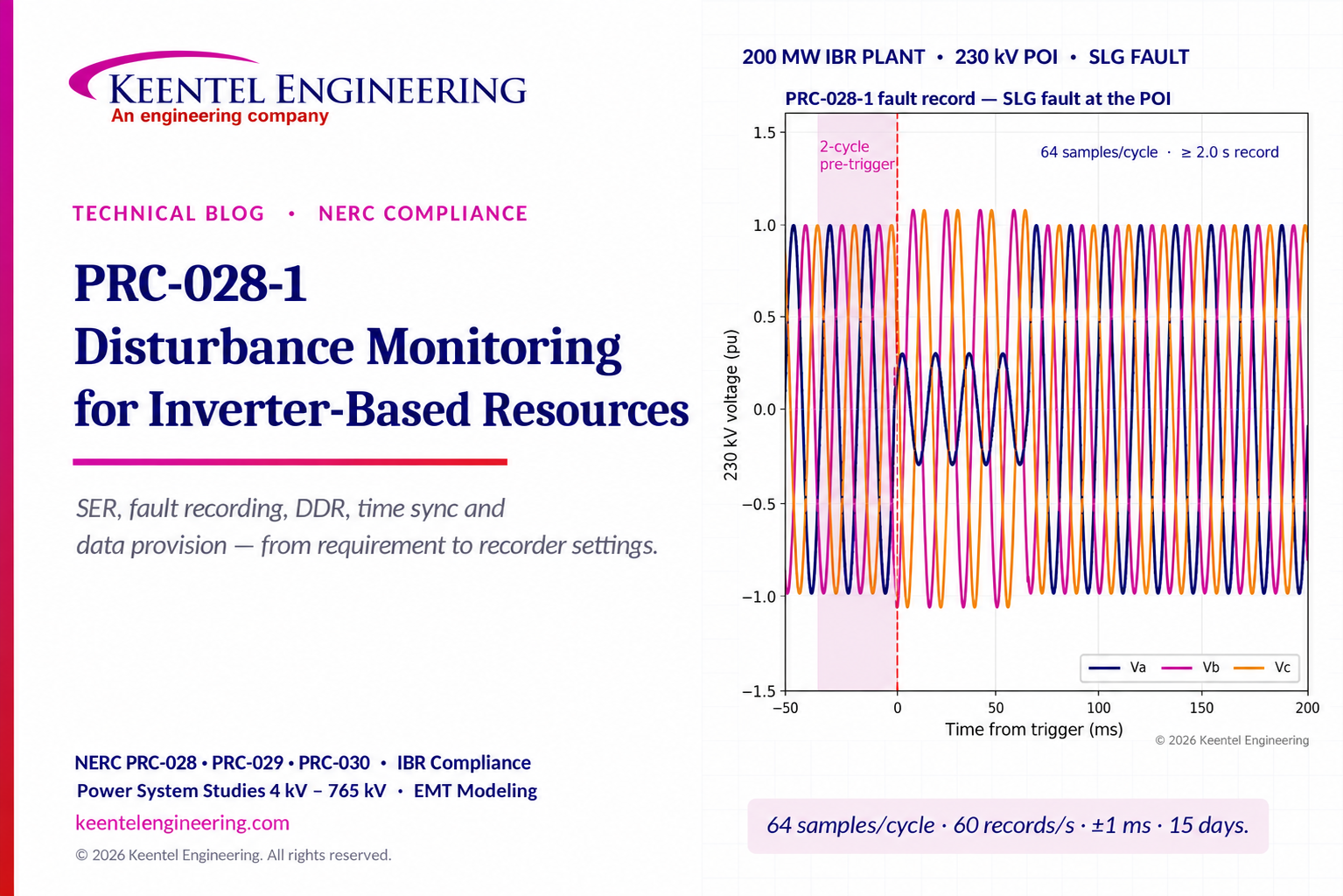
Explore NERC PRC-028-1 requirements for IBR disturbance monitoring, fault recording, SER, DDR, time synchronization, compliance deadlines and audit readiness.

By SANDIP R PATEL
•
October 26, 2026
Explore cyber-physical resilience for the Energy Internet, including DER attacks, false data injection, BESS readiness, AI detection, and NERC CIP compliance.
By SANDIP R PATEL
•
October 26, 2026
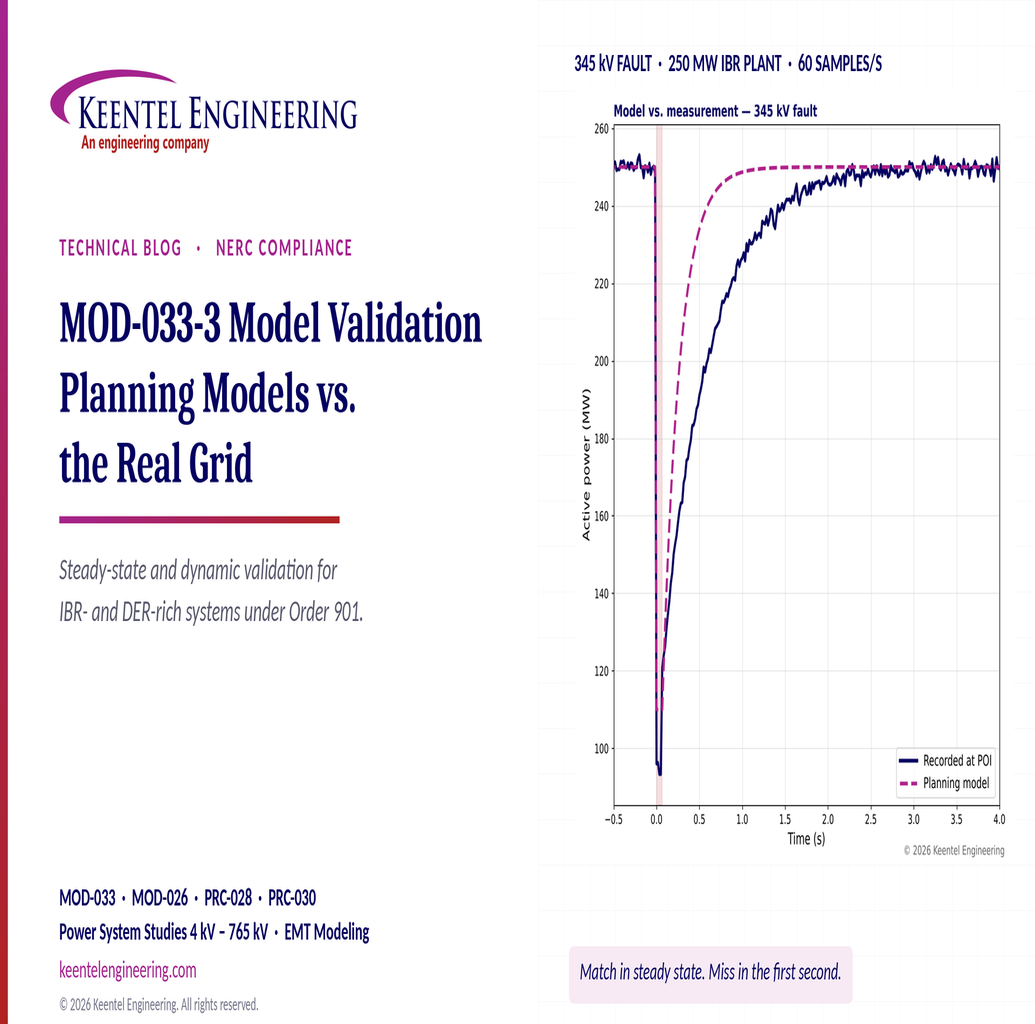
Understand MOD-033-3 requirements, IBR and DER model validation, steady-state comparisons, dynamic studies and NERC compliance.

By SANDIP R PATEL
•
October 24, 2026
Learn how Buchholz and sudden pressure relays protect transformers, detect internal faults, and meet NERC PRC-005-6 maintenance requirements.
By SANDIP R PATEL
•
October 24, 2026
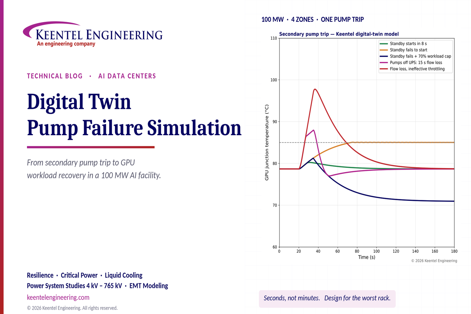
Explore digital twin pump failure simulation for liquid-cooled AI data centers, including GPU temperatures, standby pump failover, UPS and workload recovery.

By SANDIP R PATEL
•
October 24, 2026
Learn PSCAD custom component parameters, field types, Literal, Constant and Variable settings, Fortran coding, and EMT model validation for grid studies.

By Team 2 Dexora
•
October 24, 2026
Explore 800 VDC rack fault protection for AI data centers, including solid-state breakers, DC short circuits, selectivity, arc flash, and NEC/UL standards.
October 24, 2026
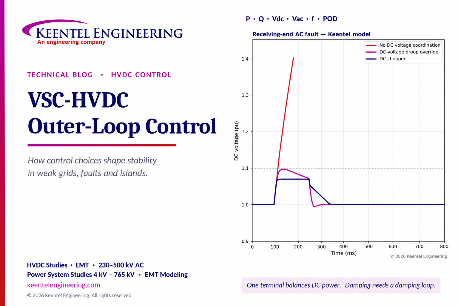
Explore VSC-HVDC outer-loop control for P, Q, DC voltage, weak-grid stability, fault ride-through and power oscillation damping with engineering models.
By SANDIP R PATEL
•
October 23, 2026
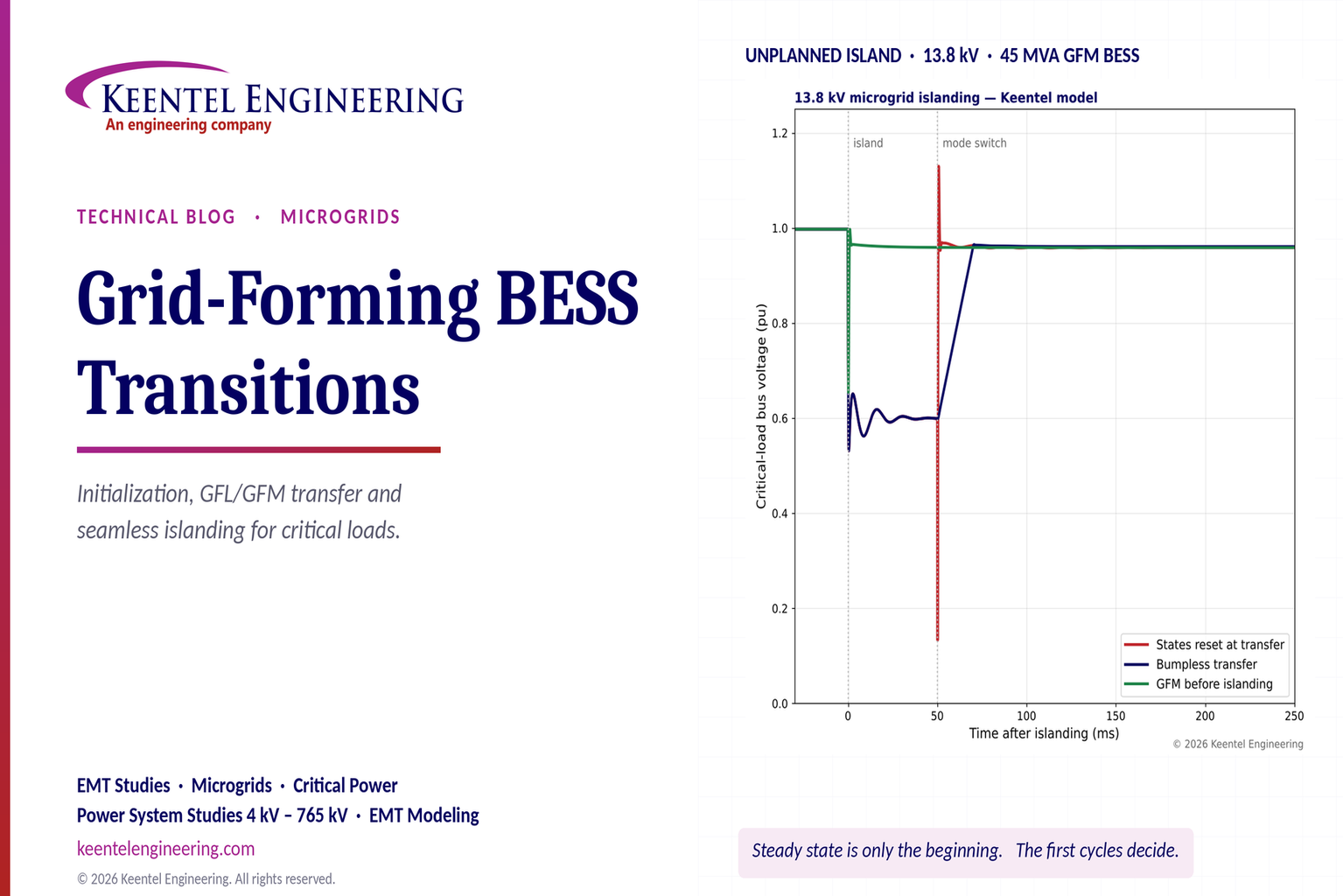
Explore grid-forming BESS initialization, GFL-to-GFM transitions, seamless islanding, EMT simulations, current limiting and microgrid protection.