A Coordinated Electric System Interconnection Review—the utility’s deep-dive on technical and cost impacts of your project.
Challenge: Frequent false tripping using conventional electromechanical relays
Solution: SEL-487E integration with multi-terminal differential protection and dynamic inrush restraint
Result: 90% reduction in false trips, saving over $250,000 in downtime
The three operating regions you have to design to
| Device | Output vs voltage | Response | Best suited to | Main limitations |
|---|---|---|---|---|
| Mechanically switched capacitor or reactor | Proportional to voltage squared | Seconds; discrete steps; limited switching operations per day | Steady-state reactive supply, voltage profile, loss reduction | No dynamic capability; step voltage change on switching; capability collapses when most needed |
| Static var compensator | Capacitive branches proportional to voltage squared | A few cycles; continuously controllable | Continuous control where cost matters and deep voltage support is not the driver | Square-law capability loss; harmonic filters are part of the plant and interact with the network |
| STATCOM | Approximately proportional to voltage — constant current capability | One to two cycles closed loop; converter response faster still | Voltage stability margin, weak interconnections, fast disturbance recovery, flicker and unbalance compensation | Higher capital cost; converter losses; adds a converter and its control dynamics to the network |
| Synchronous condenser | Governed by machine capability and excitation | Excitation response in the hundreds of milliseconds; inherent inertial response instantaneous | System strength and inertia, short-circuit contribution, black start support | Rotating plant with maintenance and losses; slower controlled response than a converter |
| STATCOM with energy storage | Reactive as a STATCOM, plus real power within the storage rating | As STATCOM for reactive; real power limited by storage | Where a real power deficiency is part of the problem | Cost and complexity of the storage; different failure and maintenance profile |
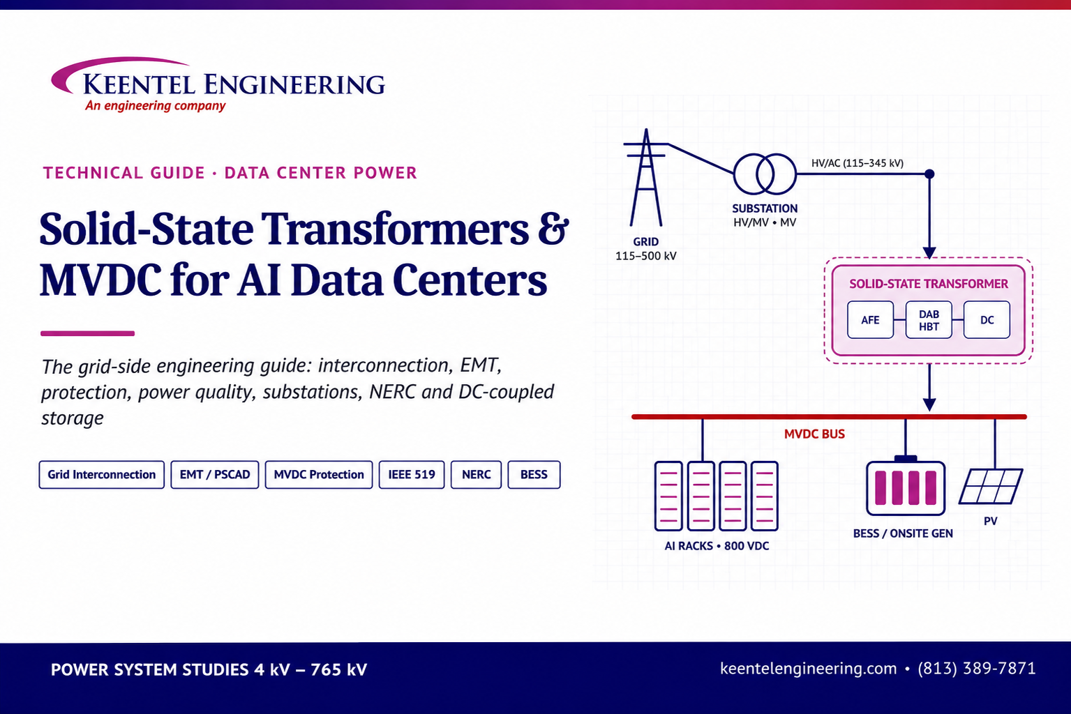
Solid-State Transformers and MVDC for AI Data Centers
November 05, 2026 | Blog
The Grid-Side Engineering Guide: interconnection, EMT modeling, MV/MVDC protection, power quality, substations, NERC compliance, owner’s engineering and DC-coupled storage
Introduction: the transformer is changing, the grid is not
The solid-state transformer (SST) is moving from the research lab to the gigawatt AI campus, and the hardest problems it creates sit outside the box. An SST replaces the 60 Hz iron-core transformer and the chain of rectifiers behind it with high-frequency power electronics. It takes medium-voltage AC from the utility, converts it, and delivers regulated DC to the data hall. For AI developers moving toward 800 VDC rack power and medium-voltage DC (MVDC) distribution, that is an attractive trade: fewer conversion stages, less copper, a smaller footprint, and a power path that the software stack can actually control.
The power electronics inside the SST are a hard engineering problem, and the teams building them are good at it. Silicon carbide devices rated near 10 kV, medium-frequency transformers, modular converter stacks and fast digital control are their domain. This guide is not about that work. Keentel Engineering does not design SST hardware.
This guide is about everything around the SST: the transmission line that brings power to the campus, the substation that steps it down, the utility study that decides whether the project can connect at all, the EMT model the planner will demand, the protection scheme on a DC bus that has no natural current zero, the harmonic limits at the point of interconnection, the NERC standards that are now reaching loads for the first time, and the owner's engineering that keeps a first-of-a-kind procurement honest. That is where SST programs will meet the grid. In our experience it is also where schedules slip.
Why this matters now
Three things changed between 2024 and 2026.
First, AI loads got big enough to move the grid. Single campuses now plan for hundreds of megawatts to several gigawatts. A campus of that size is no longer a customer on a distribution feeder. It is a transmission-level object on the same scale as a large power plant, and it can affect voltage stability, frequency response and protection across a region.
Second, the grid noticed. In July 2024, a failed lightning arrester on a 230 kV line in Northern Virginia produced six successive faults within 82 seconds, and about 1,500 MW of data center load transferred to backup power. Nothing in the grid's planning models predicted that response. The North American Electric Reliability Corporation (NERC) reviewed the event, formed a Large Loads Task Force, and began work on how computational loads should be modeled, registered and held to ride-through performance. Utilities and grid operators in Texas, New York, the Mid-Atlantic and elsewhere have since tightened their large-load interconnection requirements. Texas wrote many of those requirements into statute in 2025.
Third, the power path inside the campus is becoming power electronics end to end. A conventional data center looks to the grid like a large, mostly passive transformer bank feeding rectifiers and UPS systems. An SST-fed campus looks like a very large inverter-based resource running in reverse. Its response to a grid fault, a voltage dip or a frequency swing is set by firmware rather than by physics. That is a capability, because the response can be designed. It is also a risk, because the response has to be proven to the utility, and the utility's tools and standards were built for generators.
The gap this guide addresses
SST development teams naturally focus on the converter: topology, devices, magnetics, cooling, controls, efficiency. Their job descriptions say so. Public recruiting by at least one AI infrastructure developer for an SST technical lead, for example, describes a medium-voltage SST feeding an MVDC distribution system and lists protection, control boundaries and fault behavior at the SST/MVDC interface as open questions to resolve.
Those interface questions do not stop at the MVDC bus. They run upstream to the utility and downstream to the racks. Someone has to answer questions like these:
- What does the campus do in the first 150 ms of a three-phase fault 40 miles away, and can we prove it in a model the utility accepts?
- What fault current does the SST contribute on the AC side, and does the utility's protection still see the fault?
- How is a DC bus fault cleared when the converters limit current and there is no zero crossing?
- What harmonic and supraharmonic emissions reach the point of interconnection when hundreds of converters switch at tens of kilohertz?
- Which NERC standards apply when a load can ride through, inject reactive power and curtail on command?
- How does an owner write a specification and a factory test plan for equipment that has no mature product standard?
The rest of this guide works through those questions in eight areas. Each section explains the engineering problem, the current regulatory and standards landscape, what utilities and grid operators are asking for, and where Keentel can carry the work. The guide ends with Keentel's service offering, two anonymized and illustrative case studies, an FAQ and a list of references.
Who should read this
This guide is written for engineers and program leads at AI infrastructure developers, hyperscalers, SST and power electronics manufacturers, utilities receiving large-load requests, and investors doing technical diligence on SST-based campuses. It assumes familiarity with power systems. Where SST internals matter to the grid-side problem, the next section gives a short primer.
SST and MVDC primer for grid engineers
An SST is a three-stage power converter that the grid sees as a controllable, current-limited load with an active front end. Grid engineers do not need to design one, but they do need to know which parts of it set the behavior they will study. This section covers those parts.
The three conversion stages
Most medium-voltage SST designs for data centers share a common structure, whatever the vendor:
- AC/DC active front end (AFE). An actively switched rectifier connects to the medium-voltage AC supply, typically somewhere between 4.16 kV and 34.5 kV in North America. It draws near-sinusoidal current, controls power factor, and regulates an internal DC link. Its control loops, including the phase-locked loop (PLL), current controller and DC-link voltage controller, set almost everything the grid sees: fault response, harmonic emissions, reactive power, ride-through and interaction with other converters.
- Isolated DC/DC stage. A high-frequency inverter drives a medium-frequency transformer (MFT), typically in the range of a few kilohertz to tens of kilohertz, and a rectifier on the secondary. The MFT provides galvanic isolation and the voltage ratio. Because transformer size scales inversely with frequency, the MFT is much smaller and lighter than a 60 Hz unit of the same rating. The dual active bridge (DAB) is the most common topology here.
- Output stage. The secondary side delivers DC to a distribution bus. Depending on the architecture, that bus may be a campus-level MVDC system, a ±400 V or 800 V low-voltage DC bus feeding racks, or both in sequence.
Modular topologies
No single semiconductor can block tens of kilovolts, so MV SSTs are built from modules. Two families dominate.
Input-series, output-parallel (ISOP) stacks. Many identical cells, each with its own AFE, DAB and MFT, are stacked in series on the MV input to share the voltage and paralleled on the low-voltage output to share the current. Each cell sees a fraction of the line voltage. Redundant cells can be added so the unit keeps running when one fails. The trade-offs are voltage and power balancing across the cells, insulation of each MFT to the full line voltage, and the large count of components.
Modular multilevel converter (MMC) based designs. An MMC builds a multilevel AC waveform from submodules with their own capacitors. It is the standard topology for HVDC converter stations, scaled down. MMC-based SSTs suit higher power and an MVDC output, and they produce very low harmonic distortion on the AC side. They bring stored capacitor energy, circulating currents and more complex control.
The arrival of 10 kV silicon carbide (SiC) MOSFETs matters because higher-voltage devices mean fewer series cells, simpler insulation and higher switching frequency. It also means faster voltage transitions (dv/dt), which affect insulation stress, partial discharge and electromagnetic emissions. Those are issues for the system engineer as much as for the converter designer.
Why AI campuses want SSTs and MVDC
The push toward DC inside the data center is driven by rack power. Racks for AI accelerators have moved from tens of kilowatts toward hundreds of kilowatts, and industry roadmaps now point to megawatt-class racks. At 54 VDC or 415/480 VAC, the copper and conversion losses required to deliver that power become impractical. In 2025, NVIDIA and its ecosystem partners announced an 800 VDC architecture for future AI factories, and the Open Compute Project (OCP) has active work on high-voltage DC rack power and on solid-state transformers for data center power distribution.
An 800 VDC or MVDC architecture removes conversion stages. A traditional path converts MV AC to low-voltage AC through a 60 Hz transformer, then through UPS rectifiers and inverters, then through power supply units in the rack. An SST-fed DC path can go from MV AC to DC once and distribute DC from there. Developers cite expected benefits in efficiency, copper volume, footprint, construction speed, and the ability to integrate batteries and onsite generation directly on a DC bus.
The SST also gives the campus something a 60 Hz transformer cannot: a controllable interface to the grid. The AFE can regulate reactive power, limit inrush, ride through disturbances, smooth the fast power swings of AI training workloads, and respond to dispatch signals. Whether it does those things well depends on control design, and on whether the grid-side requirements were written into the specification early.
The system boundary
For grid-side work, the useful boundary is this. Everything inside the SST enclosure belongs to the SST designer: devices, gate drivers, magnetics, cell balancing, thermal design and internal protection. Everything the SST touches belongs to the system engineer, who must specify and verify the behavior at that boundary. On the AC side that includes the MV collector system, the step-down substation, the transmission tap and the utility grid. On the DC side it includes the MVDC or LVDC bus, DC protection, grounding, energy storage and onsite generation, and the load.
At the boundary, the system engineer needs a defined set of characteristics from the SST vendor: a validated EMT model, fault current contribution on both sides, ride-through capability curves, harmonic and supraharmonic emission spectra, the insulation and grounding design, internal protection settings and their coordination margins, and the control modes available. Most of the grid-side work described in this guide depends on getting those characteristics in a usable form, early enough to matter.
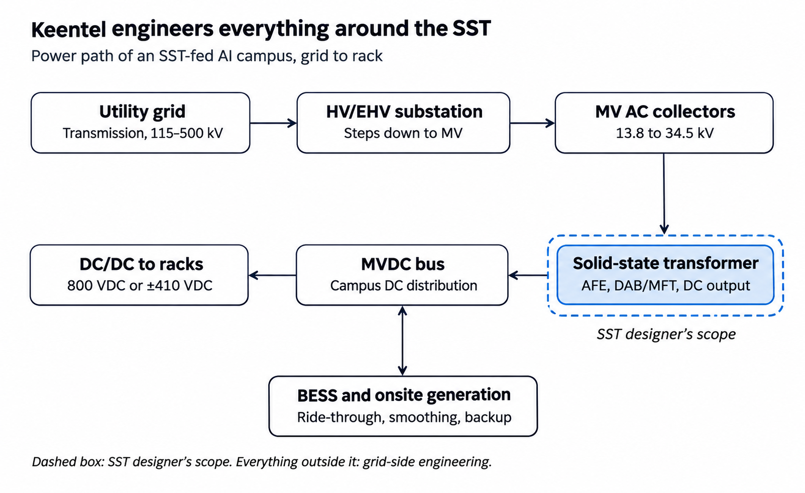
Figure 1. SST campus power path · grid to rack, with DC-side storage
Power flows from the transmission grid through the substation and MV collectors into the SST, then across the MVDC bus to the racks. Storage and onsite generation connect directly to the DC bus.
What the grid sees
From the utility's point of view, an SST-fed campus has five defining features:
- Converter-interfaced. The campus has no rotating mass and no inherent fault current beyond what the converters' firmware allows. Its behavior during disturbances is defined by control logic.
- Large and concentrated. Hundreds of megawatts to gigawatts sit behind one or two points of interconnection.
- Fast and variable. AI training workloads can swing campus demand by large fractions of nameplate within seconds, sometimes in periodic patterns.
- Potentially bidirectional. With batteries or generation on the DC bus, the campus can export or support the grid, and some operators will want it to.
- New. There is limited operating history, few validated models and no settled product standard for MV SSTs, so the utility cannot rely on precedent.
Each of the eight sections that follow addresses one part of how that profile meets the grid.
1. Grid interconnection with SST loads
The interconnection study is the critical path for most gigawatt AI campuses, and an SST front end changes what that study must prove. For a conventional load, the utility mostly asks whether the transmission system can serve the demand under normal and contingency conditions. For an SST-fed campus, the utility will also ask how the load behaves dynamically, whether it will trip during faults, what it injects, and whether it can be curtailed. Those questions require more data and more study types, and they arrive while the large-load rules themselves are still changing.
How large-load interconnection has changed
For most of the grid's history, load interconnection was a utility service process. A customer applied, the utility ran a facilities study, built or upgraded what was needed, and connected the load. Generators went through formal RTO queues with detailed technical requirements, and loads did not.
That asymmetry is ending. The drivers are scale and behavior. A 1 GW data center campus draws as much power as a large nuclear unit produces. Large clusters of data center load in Northern Virginia, Texas, Ohio, Georgia and Arizona now shape regional load forecasts. The July 2024 event in Virginia showed that these loads can disconnect in large blocks during normal grid faults, producing a sudden load loss that the system then has to absorb with overvoltage and overfrequency.
Regulators and grid operators have responded on several fronts:
- Federal. In October 2025 the U.S. Department of Energy directed the Federal Energy Regulatory Commission (FERC) to consider rules asserting jurisdiction over interconnection of
- (above 20 MW) directly to the transmission system, in Docket RM26-4. FERC also acted on co-location of large loads at generating plants in the PJM region. The scope and timing of final federal rules should be checked at the start of any project, because they are moving.
- Texas. Senate Bill 6, signed in 2025, set new requirements for large loads of 75 MW or more in ERCOT. These include disclosure of onsite backup generation, study fees and financial commitments, demonstration of site control, and provisions for curtailment or remote disconnection of new large loads during emergencies. The Public Utility Commission of Texas and ERCOT have been implementing it through rulemaking and protocol revisions, alongside ERCOT's own large-load interconnection process and ride-through work.
- Reliability standards. NERC formed a Large Loads Task Force, issued alerts on large-load behavior, and began standards and registration work for computational loads. Section 6 covers this in detail.
- Utility tariffs. Many utilities have filed large-load tariffs that require minimum demand charges, longer contract terms, collateral, and in some cases operational requirements such as ride-through and curtailment.
The practical effect is that a large-load application now looks much more like a generator application. It needs a data package, models, studies and compliance commitments.
The SST changes the technical questions
A campus built on 60 Hz transformers and conventional UPS systems still behaves in partly converter-driven ways, which is what caused the Virginia event. An SST-fed campus is converter-driven all the way through. That has consequences for each stage of the study.
Steady-state load flow. The SST's AFE can operate at unity power factor, or supply or absorb reactive power within its current rating. That can reduce the need for utility-side reactive compensation, but only if the utility accepts the capability as reliable. The study basis must state which reactive capability is assumed and under what conditions it is guaranteed.
Short circuit. An SST contributes little fault current to the AC grid, usually limited to around 1.0 to 1.5 per unit of rated current, and the contribution depends on control mode. That reduces fault duty on utility breakers, which helps. But it also changes what utility protection sees. Distance and directional elements that rely on a strong fault source on the customer side may behave differently. Section 3 covers this.
Dynamics. Positive-sequence stability tools such as PSS®E and PSLF need a dynamic model of the campus. Standard load models (ZIP, induction motor and composite models) do not represent an SST. Recent work by NERC and the industry has produced generic models for power-electronic and data center loads, but a vendor-specific, validated model is the safer basis for a first-of-a-kind design. Section 2 covers the EMT side, which the utility increasingly expects as well.
Ride-through and load loss. The utility will want to know the largest block of campus load that can be lost for any single fault, and how fast. An SST campus designed to ride through grid faults can reduce that figure substantially. One designed with fast protective trips on undervoltage can make it worse than a conventional design. The study must evaluate the worst credible event and show the system survives it.
Fluctuating demand. Large AI training jobs can cause campus demand to swing sharply and periodically, as thousands of accelerators move between compute and communication phases in step. Utilities have started asking for power-ramp and oscillation characteristics. An SST with energy storage on the DC side can smooth those swings before they reach the grid, which is a strong argument in the interconnection request.
Market-by-market view
The process differs by region. The table below summarizes the features most relevant to an SST campus. Requirements are changing quickly, and each entry should be confirmed against the current tariff, manuals and utility requirements at project start.
| Market | Who studies the load | Features that matter for an SST campus |
|---|---|---|
| ERCOT (Texas) | Transmission service provider with ERCOT review, under the large-load interconnection process | SB 6 requirements for loads of 75 MW or more; curtailment and remote-disconnect provisions; disclosure of backup generation; ongoing work on ride-through for large electronic loads; option to participate as a controllable load resource |
| NYISO (New York) | Transmission owner with NYISO review of system impacts | Large loads assessed for system impact in coordination with the transmission owner; state policy interest in large energy-intensive loads; dense 345 kV and 115 kV networks with local constraints; strong winter and summer reliability margins |
| PJM (Mid-Atlantic, Midwest) | Transmission owner, with PJM load forecast and planning processes | Largest data center load growth in the U.S.; co-location rules after FERC action; large-load additions treated as a critical reliability and resource-adequacy issue |
| Other RTOs and vertically integrated utilities (MISO, SPP, Southeast, West) | Utility, often under a large-load tariff | Increasing use of large-load tariffs with minimum bills, collateral and operating requirements; varying expectations for models and ride-through |
Our flyer series and service pages describe these processes in more depth. For an SST campus, the common thread is that every market now expects models and behavior commitments that a conventional load would not have provided.
What the utility will ask for
Based on current practice, an SST campus should expect to provide most of the following, and should prepare them before the utility asks:
- A single-line diagram from the point of interconnection to the SST terminals, with equipment ratings.
- Load ramp schedule by phase, with peak, minimum and expected operating demand.
- Reactive capability and power factor commitments across the operating range.
- Positive-sequence dynamic models in the utility's platform, with parameter justification.
- EMT models (usually PSCAD) of the SST and campus controls, with documentation and validation evidence.
- Voltage and frequency ride-through capability, stated as curves and tested against the utility's or RTO's requirements.
- Harmonic emission data and a harmonic compliance study at the point of interconnection.
- A description of power fluctuation behavior and any smoothing or ramp-rate controls.
- Protection philosophy and settings that interact with the utility's protection.
- Backup generation and storage details, including any export or islanding capability.
- Curtailment and demand response capability, where the market requires it.
- NERC registration analysis, if applicable.
Where projects lose time
The schedule risks we see most often are avoidable:
- No model when the study starts. The utility cannot start dynamic or EMT studies without a model. SST vendors at an early stage often have detailed internal models that are not packaged for utility use. Getting a usable, documented model can take months.
- Behavior assumed, not specified. If ride-through, reactive capability and harmonic limits are not in the SST purchase specification, the vendor has no obligation to deliver them. The utility will hold the developer to them anyway.
- Study scope that ignores the DC side. Storage and generation on the MVDC bus change what the grid sees. If they are added after the study, the study may have to be redone.
- Late discovery of weak-grid conditions. A campus sited at a weak point in the network can face control stability problems that only EMT analysis reveals. Early screening for short-circuit ratio avoids that surprise.
How Keentel helps
Keentel prepares and reviews large-load interconnection applications and supports developers through utility and RTO studies. For SST campuses, that includes:
- Interconnection strategy and site screening, including short-circuit strength, available capacity and likely network upgrades.
- Preparation of the technical data package, including single-line diagrams, ratings, models, ride-through and harmonic data.
- Independent load flow, short-circuit, contingency and stability studies across 4 kV to 765 kV, so the developer knows the likely answer before the utility delivers it.
- Review of utility study results, upgrade assignments and cost estimates.
- Representation in technical meetings with the utility and RTO.
- Ongoing tracking of large-load rules in ERCOT, NYISO, PJM and other markets.
2. EMT modeling of SST-fed campuses
An SST is an inverter-based load, and utilities have learned that inverter-based equipment must be studied in electromagnetic transient (EMT) simulation before it connects. The industry learned this lesson from solar, wind and battery plants. A series of NERC disturbance reports from 2016 onward traced large unexpected losses of inverter-based generation to control and protection behavior that positive-sequence models did not capture. Utilities responded by requiring EMT models and studies for inverter-based resources. They are now extending the same expectation to large converter-based loads.
Why positive-sequence models are not enough
Positive-sequence (RMS) stability tools such as PSS®E and PSLF solve the network at fundamental frequency with time steps of a few milliseconds. They assume balanced conditions and average out fast dynamics. They are the right tool for system-wide studies of thousands of buses, but they cannot represent the things that make converters fail:
- PLL behavior during deep voltage dips, phase jumps and unbalanced faults.
- Fast current-control dynamics and their interaction with the network impedance.
- DC-link voltage swings and internal protection trips that act within a cycle.
- Negative-sequence current control during unbalanced faults.
- Harmonic and control interactions between converters and with series capacitors, HVDC links, filters and cables.
- Saturation, switching transients and protection behavior during energization.
EMT simulation solves the network in the time domain with microsecond time steps. It represents each phase, real control code or a detailed model of it, and the frequency-dependent behavior of lines and transformers. PSCAD/EMTDC is the most widely used EMT platform in North American utility practice. Other tools, including EMTP, PowerFactory in EMT mode and real-time simulators, are also used.
What an EMT study of an SST campus covers
For a gigawatt campus, the EMT study is not one simulation. It is a set of studies, each answering a specific question the utility or the owner will ask.
Model quality and acceptance tests. Before any system study, the model itself must be checked. Typical checks include initialization to a flat steady state, response to step changes in voltage and power, behavior at different time steps, and performance in the utility's simulation environment. Many utilities and RTOs now publish EMT model requirements specifying documentation, the use of vendor-specific control code, and a defined set of benchmark tests.
Fault ride-through. The campus model is subjected to balanced and unbalanced faults at the point of interconnection and at remote locations, with a range of clearing times and post-fault network strengths. The study verifies that the SSTs stay connected and return to pre-fault power within the required time, and identifies any internal protection, including DC-link overvoltage, overcurrent, PLL loss of lock and AC undervoltage, that trips too early.
Voltage and frequency response. The study checks behavior during voltage swells, high and low frequency excursions, rate-of-change-of-frequency events and phase-angle jumps. It also checks the reactive current the AFE supplies during and after faults and whether it helps or harms voltage recovery.
Weak-grid stability. Converter control stability depends on the strength of the network at the connection point, usually expressed as the short-circuit ratio (SCR): the available fault level divided by the converter rating. A gigawatt of converters at one site can drive the effective SCR low, especially when nearby inverter-based generation is also counted. At low SCR, PLL and current controllers can become oscillatory or unstable. The study evaluates stability across a range of network strengths, including outage conditions, and identifies the minimum SCR for stable operation.
Control interactions. Hundreds of SST modules on one campus, each with its own controller, must not interact badly with each other or with nearby equipment. The study looks for oscillations between converters, with nearby inverter-based generation, with series-compensated lines, with STATCOMs and SVCs, and with HVDC terminals. Sub-synchronous control interaction near series capacitors deserves a specific screen.
Harmonic and resonance behavior. EMT simulation can show how converter switching and control interact with network resonances, especially with long cables and capacitor banks. Section 4 treats harmonics in depth. EMT is one of the tools for checking resonance risk.
Energization and switching. Energizing large MV collector systems, filters and SST input stages produces inrush and switching transients. The study verifies that these stay inside equipment and utility limits.
Load swings and oscillations. The study models the campus power profile under realistic AI workload patterns, including synchronized steps and periodic oscillations, and checks the effect on voltage at the point of interconnection and on nearby generator torsional modes. It also verifies that any smoothing control or DC-side storage works as intended.
Campus-scale modeling challenges
A gigawatt campus may contain several hundred SST modules. Modeling each one in full switching detail would be slow and unnecessary for most system questions. A practical model has layers:
- Detailed module model. A single SST module with full switching detail, used to validate the vendor model and study internal behavior and protection.
- Average-value module model. The same controls with switching replaced by averaged sources, much faster, used for system studies after it has been checked against the detailed model.
- Aggregated campus model. Groups of modules represented as equivalent converters on each MV collector, with collector impedance and transformer data, used for system studies at the point of interconnection.
The aggregation must preserve the behaviors that matter. If modules have different settings, staggered ride-through thresholds or different control modes, aggregation can hide a partial trip. The modeling plan should state the aggregation method and include sensitivity cases showing that it does not change the result.
Vendor model readiness
The most common delay is not the simulation. It is the model. For a new SST product, the vendor may have detailed simulation models built for internal design work in tools that are not acceptable to the utility, or may be unwilling to release control code. Utilities generally want models that use the actual control code, compiled and protected if necessary, so that the model behaves like the field equipment.
Owners should require, in the SST purchase specification:
- A PSCAD-compatible EMT model using the actual control code, delivered by a specified date.
- A positive-sequence model in the utility's platform, with the correct parameters and documentation.
- A model user guide, parameter list, and the set of benchmark results the utility requires.
- Agreement to update the models when firmware changes, and to support validation against factory and field tests.
- Permission to share the models with the utility, RTO and the owner's consultants under confidentiality.
Model validation after commissioning
The EMT model used in the interconnection study is a prediction. After commissioning, it must be compared with measured behavior. For generators, NERC standard MOD-026 has long required verification of excitation and governor models, and the newer MOD-026-2 consolidates and extends model verification to inverter-based resources. Requirements for loads are still developing, but a campus that can show its model matches field measurements will be in a strong position with its utility and with future NERC requirements. That requires high-resolution monitoring at the point of interconnection and on major collectors, discussed in Section 6.
How Keentel helps
Keentel delivers EMT studies with PSCAD/EMTDC and positive-sequence studies with PSS®E, PSLF and PowerFactory through its engineering team and qualified study partners. For SST campuses, that includes:
- EMT model requirements for the SST specification, and review of vendor models for completeness, quality and utility acceptance.
- Model benchmarking and acceptance testing against utility and RTO requirements.
- Campus-scale aggregated models with documented aggregation methods.
- Ride-through, weak-grid, control interaction, energization and load-oscillation studies.
- Short-circuit ratio screening at candidate sites before land is committed.
- Coordination of positive-sequence and EMT model consistency.
- Post-commissioning model validation support.
3. MV/MVDC system studies: faults, protection, arc flash, grounding and insulation
The SST/MVDC interface is where conventional power system practice runs out, and the developer has to define the system engineering at that boundary itself. AC protection is a mature discipline with decades of standards, relay products and settings practice. MVDC distribution for data centers is not. Experience exists in ships, rail traction, HVDC stations and some industrial plants, but there is no settled utility-style practice for a campus MVDC network feeding critical IT load. This section covers the five system studies that define that boundary.
Short-circuit and fault behavior
AC side. On the AC side, the SST behaves like an inverter-based resource. Its fault current is set by the AFE current limit, typically close to rated current, perhaps up to 1.5 per unit for a short time. It has no subtransient contribution like a motor or generator. This has three effects:
- Fault duty on MV switchgear and utility breakers is set mostly by the utility source and any conventional equipment on the campus. SSTs add little.
- Protection that relies on current magnitude from the campus side may not operate as expected for faults on the utility system or on the campus MV collectors.
- The AFE's negative-sequence current control during unbalanced faults determines what directional and negative-sequence elements see, and it varies by vendor. The utility's protection engineers will need to know which control strategy is used.
Short-circuit studies on the AC side therefore need two parts: a conventional study of maximum fault duty for equipment rating, using IEEE C37 and ANSI methods, and a converter-aware study of what the SSTs contribute during faults for protection setting. The second part comes from the EMT model or vendor-supplied fault current profiles.
DC side. DC faults are different in kind. When a pole-to-pole or pole-to-ground fault occurs on an MVDC bus, the first current comes from the DC-link and filter capacitors in every converter connected to the bus. That discharge can reach very high peak current within microseconds to milliseconds, limited only by the cable and bus inductance and resistance. After the capacitors discharge, the sustained contribution depends on the converters. Some topologies can block and stop feeding the fault. Others, such as a two-level voltage-source converter with uncontrolled freewheeling diodes, can continue to feed fault current from the AC side through the diodes.
A DC short-circuit study therefore has to model:
- Capacitor discharge from every converter on the bus, including SST output stages, battery converters and DC/DC converters.
- Cable and busway inductance and resistance, including the location of the fault.
- Converter blocking behavior and its timing.
- Storage contribution, which can be large and sustained if the battery interface does not current-limit.
- The interaction of all of these with the protection devices chosen.
IEC 61660 gives methods for calculating short-circuit currents in DC auxiliary installations, and IEEE 946 covers DC auxiliary power systems in generating stations. Neither was written for a megawatt-scale MVDC data center bus. In practice, the DC fault study uses EMT simulation with the vendor models, supported by hand calculation for bounding cases.
DC protection: the open interface question
AC circuit breakers interrupt current at a natural zero crossing, which happens 120 times a second at 60 Hz. DC current has no zero crossing. Interrupting it requires creating one or absorbing the energy in some other way. That is why DC protection is the defining technical issue of the SST/MVDC interface.
The main options are:
- Converter-based protection. Converters that can block quickly limit the fault and de-energize the bus, and then mechanical disconnectors open the faulted section with no current. This is simple and cheap, but it takes down the whole bus section and relies on fast, selective fault location.
- Solid-state DC circuit breakers. Semiconductor switches interrupt within microseconds, with surge arresters to absorb the inductive energy. They are fast and selective, but they have conduction losses and high cost at MV.
- Hybrid DC circuit breakers. A mechanical switch carries the normal current, and a parallel solid-state path performs the interruption. They have low loss and fast interruption, but they are complex, and MV products are still maturing.
- Fuses and current limiters. These are useful on smaller branches and LVDC racks, but coordinating them on a large MVDC bus is difficult.
The protection design must answer several questions together:
- Selectivity. Can a fault on one feeder be isolated without dropping the whole bus? That requires fault location fast enough to act before converters block on their own.
- Speed versus equipment withstand. How fast must interruption happen to protect semiconductors, capacitors and cables? A DC fault can damage converter devices within microseconds.
- Coordination with internal SST protection. SST internal protection must not trip before the external system protection has a chance to isolate the fault, and it must not fail to trip when the external protection fails. That needs defined time and current margins, agreed with the vendor.
- Backup protection. What happens if the primary DC breaker fails? Breaker failure logic on a DC system needs as much thought as on an AC system.
- Restoration. How quickly can the healthy part of the bus be re-energized, and does that sequence create its own transients?
There is some useful precedent. IEEE 1709 gives recommended practice for 1 kV to 35 kV MVDC systems on ships, including protection and grounding considerations. HVDC practice offers protection philosophy for converter stations. OCP and industry groups are actively working on DC protection for data centers. None of these yet provides a complete, accepted rulebook for a campus MVDC network, so the protection philosophy must be developed and documented project by project.
AC-side protection also changes. Protection of the MV collector system feeding SSTs must account for low converter fault current and for the possibility that a fault on the collector is fed mainly from the utility side. Line differential and directional schemes, transformer differential protection that handles harmonics in SST input current, and the coordination of SST input protection with feeder breakers all need specific attention.
Arc flash
Arc flash studies for AC systems follow IEEE 1584-2018, which provides empirical models for three-phase AC systems from 208 V to 15 kV. Above 15 kV, practitioners use alternative methods such as theoretical maximum power or Lee-based calculations. NFPA 70E requires an arc flash risk assessment for work on energized equipment and is the basis for incident energy labels and PPE.
DC arc flash is less settled. IEEE 1584 does not cover DC. NFPA 70E's informative material refers to methods for DC incident energy, including maximum power and published models by Doan, Paukert, and Stokes and Oppenlander. These methods were mostly developed for battery systems, photovoltaic arrays and low-voltage DC, and they tend to be conservative. At MVDC levels, with large capacitor energy available in milliseconds, they need careful judgment.
For an SST campus, the arc flash study should cover:
- MV AC switchgear and collectors, with IEEE 1584 or appropriate alternatives above 15 kV, using upstream utility fault current and protection clearing times.
- SST enclosures, where the vendor must define accessible energized parts and internal arc ratings. Internal-arc-classified enclosures can greatly reduce risk.
- MVDC switchgear and busway, with DC methods, capacitor discharge energy and protection clearing times.
- LVDC distribution and racks at 800 VDC or ±400 VDC, where the large number of workers and frequent maintenance make the labels and procedures especially important.
- Battery systems on the DC bus, which have their own arc flash and shock hazards and their own guidance in NFPA 855 and NFPA 70E.
Arc flash results also feed back into design. Faster protection, current-limiting devices, remote racking, arc-resistant equipment and maintenance-mode settings all reduce incident energy. A first-pass study during design is more valuable than a label study at commissioning.
Grounding
Grounding is often where AC and DC thinking conflict, and where an SST campus needs a single coherent philosophy.
Station and campus grounding. The substation ground grid must meet IEEE 80 for step and touch potentials. On a large campus, the substation, SST pads, data halls and storage yards are connected by a ground network, and fault currents from the utility system can produce ground potential rise across it. The study models the soil, the grid and the fault current split and verifies safety limits.
MV AC system grounding. The MV collector system's grounding method, whether solid, low-resistance or high-resistance, sets the ground fault current and the protection approach. SST input stages and their insulation must be compatible with the chosen method and with the temporary overvoltages it allows on unfaulted phases.
MVDC system grounding. The MVDC bus can be grounded at the midpoint, grounded through high resistance, or left floating with insulation monitoring. Each choice changes the DC ground fault behavior:
- A solidly grounded midpoint makes a pole-to-ground fault a high-current event that must be cleared quickly.
- High-resistance grounding limits ground fault current and allows continued operation during a first fault, with detection and alarm, but it allows pole voltages to shift toward full bus voltage relative to ground. Insulation must be rated for that.
- A floating system behaves similarly but requires reliable insulation monitoring and a defined response to a first fault.
Common-mode voltage and high-frequency currents. SSTs and DC/DC converters switch fast, and parasitic capacitance between windings, cables and ground lets common-mode currents flow at high frequency. These can cause bearing currents in rotating equipment, interference with communications and sensors, nuisance ground fault relay operation and insulation stress. Grounding and bonding design must provide low-impedance paths at high frequency, not just at 60 Hz.
Insulation coordination
Insulation coordination matches insulation strength to the voltage stresses the system will actually see. For AC systems, IEEE 1313.1 and 1313.2 and IEC 60071 cover the method. For SST and MVDC systems, several new stresses must be added:
- Fast transients from SiC switching. Very high dv/dt at each switching event stresses insulation in MFTs, cables and connected equipment, and can cause partial discharge in insulation that would be fine at 60 Hz.
- DC stress on insulation. Insulation under sustained DC behaves differently from insulation under AC. Space charge accumulates, and field distribution depends on resistivity, which varies with temperature. Cables and bushings for MVDC must be rated for DC.
- Pole-to-ground voltage shifts. With high-resistance or floating DC grounding, a ground fault on one pole can put the healthy pole at full bus voltage to ground.
- Lightning and switching surges from the AC grid, which pass through the substation and MV system to the SST input. Surge arrester selection and placement must protect the SST without interfering with its operation.
- Temporary overvoltages during load rejection, ferroresonance or unbalanced faults on the MV system.
The insulation coordination study defines arrester ratings and locations, basic insulation levels for AC equipment, DC insulation levels for cables, busway and switchgear, and clearance and creepage requirements. It must be agreed with the SST vendor, because the SST's own insulation design is part of the coordination.
How Keentel helps
Keentel performs MV and HV system studies and develops protection philosophies across 4 kV to 765 kV. For the SST/MVDC interface, we provide:
- AC and DC short-circuit studies, including capacitor discharge and converter contribution, using vendor models.
- Protection philosophy for the MVDC network, including device selection, selectivity, backup and restoration, and coordination with SST internal protection.
- AC protection design and settings for MV collectors, transformers and the utility interface.
- AC and DC arc flash studies, with design recommendations to reduce incident energy.
- Substation and campus grounding studies to IEEE 80, and MV and MVDC system grounding philosophy.
- Insulation coordination studies covering AC surges, DC stress and fast switching transients.
- Clear interface documents that define what the SST vendor must deliver and guarantee at the boundary.
4. Power quality: harmonics, supraharmonics and filter design
A well-designed SST front end draws cleaner current than the six-pulse and twelve-pulse rectifiers it replaces, but a gigawatt of them can still violate limits at the point of interconnection. The reasons are scale, resonance and frequency range. Low individual distortion multiplied across hundreds of modules, amplified by a network resonance, can exceed the limits that apply at the point where the campus meets the utility. And SSTs move emissions into a frequency range that the main North American harmonic standard was not written to cover.
The governing standard: IEEE 519-2022
IEEE 519-2022 is the recommended practice for harmonic control in North America, and most utility tariffs and interconnection agreements refer to it. Key points for a large SST campus:
- Point of evaluation. Limits apply at the point of common coupling (PCC), normally the point of interconnection with the utility, not at each SST.
- Current distortion limits. Limits on individual harmonic currents and on total demand distortion (TDD) depend on the ratio of the short-circuit current at the PCC to the maximum demand load current (ISC/IL) and on the system voltage. Systems above 161 kV have the tightest limits. A gigawatt campus at a moderately strong 345 kV bus may still sit in a low ISC/IL band, which tightens its limits.
- Voltage distortion limits. The utility is responsible for limiting voltage distortion at the PCC, but a large load that drives distortion over the limit will be asked to fix it.
- Measurement basis. The 2022 revision clarified statistical evaluation over very short (3-second) and short (10-minute) intervals, using 95th and 99th percentile values, and measurement according to IEC 61000-4-7 and IEC 61000-4-30.
- Frequency range. IEEE 519 limits generally cover harmonics up to the 50th order (3 kHz at 60 Hz). It acknowledges higher-frequency emissions but does not set firm limits for them.
Utilities may also impose their own requirements, which can be stricter than IEEE 519 or can cover interharmonics, voltage flicker and notching.
Emissions from an SST campus
The AC current drawn by an SST AFE contains several components:
- Low-order characteristic and non-characteristic harmonics from imperfect control, DC-link ripple, dead time, grid voltage distortion and unbalance. These are usually small per unit but add up across many modules.
- Interharmonics from interactions between the AFE control and the DC side, including load fluctuations at frequencies not related to 60 Hz.
- Switching-frequency emissions at the converter's switching frequency and its multiples. With modular multilevel or interleaved designs, the effective frequency seen by the grid can be much higher than each device's switching frequency.
- Supraharmonics in the 2 kHz to 150 kHz range. Fast SiC switching shifts emissions into this band. IEC is developing emission and immunity requirements in this range, but North American practice is still forming.
Two campus-level effects matter most:
Aggregation. Harmonic currents from different modules add according to their relative phase angles. Low-order harmonics from identical modules under similar conditions tend to add closely to arithmetic sums. Higher-frequency components with different switching phases tend to partially cancel. Interleaving switching carriers across modules can be designed to cancel specific switching harmonics, but only if the vendor's control supports it and the campus design preserves it. IEC TR 61000-3-6 summation exponents give a starting point, but vendor data and EMT simulation are better.
Resonance. A large campus has long MV cable runs, possibly capacitor banks or filters, and transformer and line impedance on the utility side. Together they form parallel and series resonances. If a resonance sits near a frequency that the SSTs emit, a small current can produce a large voltage distortion. Cable-rich MV collector systems often have resonances in the low kilohertz range, right where SST emissions can sit. The AFE's own control also has an output impedance that may be negative at some frequencies, which can destabilize a resonance. That is a control interaction problem and a harmonic problem at the same time.
The harmonic study
A defensible harmonic study for an SST campus includes:
- Utility network model. Frequency-dependent impedance of the utility system at the PCC across the range of credible system configurations, usually supplied by the utility as impedance envelopes or loci.
- Campus network model. MV collector cables, transformers, filters, capacitor banks and the SST input filters, with frequency-dependent parameters.
- SST emission model. Harmonic current spectra from the vendor, preferably measured, across load levels and grid conditions, plus the converter's frequency-dependent output impedance.
- Frequency scan. Impedance seen from the PCC and from each SST connection point across the frequency range, identifying resonances.
- Emission assessment. Harmonic currents and voltages at the PCC compared with IEEE 519 and utility limits, across load levels and network configurations.
- Background distortion. Existing voltage distortion on the utility bus, measured before construction if possible, which can be amplified by campus resonances.
- Sensitivity and contingency cases. Outages of utility lines, campus transformers or filters, and partial campus operation.
- Supraharmonic assessment. Emissions above 3 kHz, their effect on equipment and communications on the campus, and any utility requirements.
Filter sizing and mitigation
If the study shows limits will be exceeded or resonance risk is unacceptable, the options include:
- Requiring better SST performance. Lower emission limits in the SST specification, interleaving across modules, or control tuning to give the AFE a passive (positive-damping) impedance across the frequency range of concern.
- Passive filters. Tuned or high-pass filters at MV collector buses or at the PCC. Filters must be designed with resonance in mind, because adding capacitance moves resonances. They also supply reactive power, which must be balanced with the AFE's reactive control.
- Damping. Resistive damping in filters or C-type filters can reduce resonance peaks with modest losses.
- Network design. Changing cable lengths, transformer impedances or the number of collector circuits can move resonances away from emission frequencies.
- Active filtering. The SST AFEs themselves can be controlled to cancel specific harmonics, if the vendor supports it.
Filter design for an SST campus must be done together with the EMT and control interaction studies. A filter that solves a 5th harmonic problem can create a control instability at another frequency.
Other power quality issues
Voltage fluctuation and flicker. AI training workloads can cause rapid, periodic power swings. On a weak network, these produce voltage fluctuations at the PCC that may exceed flicker limits under IEEE 1453 or the utility's own criteria, and may affect other customers. The study evaluates the campus power profile against these limits and sizes any smoothing control or storage.
Voltage unbalance. SSTs can draw balanced current from an unbalanced supply, and some designs can actively compensate unbalance. Utility unbalance limits at the PCC should be checked.
Immunity. The SSTs and the campus must tolerate the utility's power quality, including voltage sags, swells, transients and existing distortion, without tripping. ITI (CBEMA) and SEMI F47 curves are common reference points for IT equipment, but the SST is now the interface, and its immunity must meet the ride-through requirements in Sections 2 and 6.
Monitoring
Power quality monitoring at the PCC and at key campus buses should be designed in from the start. Monitors should meet IEC 61000-4-30 Class A, record harmonics, interharmonics, flicker and events, and if possible capture waveform data at high sampling rates to observe supraharmonics. These records support IEEE 519 compliance, troubleshooting and model validation.
How Keentel helps
Keentel performs harmonic and power quality studies for utility-scale generation, storage and large loads. For SST campuses, we provide:
- Harmonic emission requirements for SST specifications, including supraharmonic data and frequency-dependent impedance.
- Frequency scans and resonance analysis of the campus and utility network.
- IEEE 519-2022 compliance assessments at the point of interconnection.
- Filter design and sizing, coordinated with reactive power and control interaction studies.
- Flicker and voltage fluctuation assessment for AI workload profiles.
- Pre-construction background measurements and post-commissioning compliance monitoring plans.
Keentel performs harmonic and power quality studies for utility-scale generation, storage and large loads. For SST campuses, we provide:
- Substation design at 13.8, 34.5, 69, 115/138, 230, 345 and 500 kV and above, including physical layout, bus configuration, grounding, protection and control, and drawing packages, with civil and structural work coordinated with licensed partners.
- Selection of MV level and transformer impedance, coordinated with the SST vendor and with the stability and fault studies.
- Transmission line design, routing support, reconductoring and uprating.
- Utility interface protection design and coordination, including communication-assisted schemes, transfer trip and reclosing.
- Reliability analysis of the transmission-to-SST power chain.
- Specifications and procurement support for long-lead equipment such as power transformers, breakers and GIS.
- Power system studies across 4 kV to 765 kV to support every design decision.
6. NERC compliance for large and computational loads
NERC reliability standards have historically applied to generators, transmission owners and operators, and balancing authorities, not to end-use loads. Large computational loads are changing that. The scale and converter-driven behavior of AI campuses now pose reliability risks comparable to large generators, and NERC has started treating them that way. For an SST campus, that means compliance planning belongs in the design phase, not after energization.
What changed
The July 2024 Northern Virginia event, in which about 1,500 MW of data center load transferred to backup power in response to a series of faults on one 230 kV line, was the turning point. NERC's review found that the load reduction resulted from protective settings and ride-through behavior in data center power systems, which the planning models did not represent. Since then, NERC has:
- Formed a Large Loads Task Force to assess the reliability risks of large loads and recommend actions.
- Issued a Level 3 Alert on May 4, 2026 with seven essential actions for planners, transmission owners and operators. These include compiling computational-load models and settings, studying stability margins at least annually, setting up commissioning processes for computational loads, installing dynamic fault recorders, and building communication with these loads. Responses were due August 3, 2026. A companion Reliability Guideline, Risk Mitigation for Emerging Large Loads, serves as a bridge while formal standards are updated.
- Begun work on how computational and other large loads should be modeled in planning studies.
- Begun considering changes to its registration criteria and standards so that large loads, or the entities that own or operate them, can be held to performance requirements such as ride-through.
The details of any new registration category or standard should be confirmed at the time of design. The direction is clear: large loads will increasingly be expected to meet performance and data requirements similar to those for inverter-based generation.
Standards that already reach large loads
Even before any load-specific registration, several standards already shape what a large load must do, through the transmission owner and planner:
- FAC-001 and FAC-002. Transmission owners must publish facility interconnection requirements, including for end-user facilities, and planners must study the reliability impact of new interconnections. Utilities are using these requirements to impose ride-through, modeling and data obligations on large loads.
- TPL-001. Transmission planning studies must model loads accurately enough to assess performance under contingencies. Utilities need validated campus models to meet this obligation.
- MOD-032 and MOD-033. Planning model data requirements and validation obligations flow down to the data the campus provides.
- EOP-011 and load-shedding programs. Emergency operations plans and load shedding programs must account for large loads, including whether they can be curtailed.
- Interconnection agreements and tariffs. Many of these obligations reach the campus through contracts rather than directly.
Standards that may reach an SST campus
If a campus has onsite generation or storage that can export, or if it registers as a generator owner or operator, a further set of standards applies directly:
- Inverter-based resource registration. NERC has extended generator owner and operator registration to smaller inverter-based resources connected at 60 kV or above with aggregate capacity of 20 MVA or more. A campus with significant battery or solar capacity on the DC bus behind an SST that can export may fall into this category.
- PRC-024 and PRC-029. PRC-024 governs frequency and voltage protection settings for generating resources. PRC-029-1 sets ride-through performance requirements specifically for inverter-based resources. If the SST is the grid interface for exporting storage or generation, these requirements may apply to its ride-through behavior.
- PRC-030. Requires inverter-based resource owners to identify and address unexpected changes in output during disturbances.
- MOD-026-2. Model verification for generating resources, including inverter-based resources, consolidating the earlier MOD-026-1 and MOD-027-1 requirements.
- PRC-002 and disturbance monitoring. Requirements for recording data during disturbances.
- VAR, BAL and other operating standards depending on the functions registered.
Whether these apply depends on registration, export capability and the specific configuration. The design team should know the answer before the battery yard is sized.
Ride-through requirements
Ride-through is the performance requirement most likely to affect SST design. Requirements for generators are well defined in PRC-024, PRC-029 and IEEE 2800-2022, the standard for inverter-based resource interconnection to transmission. Requirements for loads are emerging through utility interconnection requirements, ERCOT revisions and NERC's large-load work. They generally cover:
- Voltage ride-through. Staying connected and returning to pre-disturbance consumption during and after defined voltage dips and swells, with defined durations.
- Frequency ride-through. Staying connected over a defined frequency range and rate-of-change-of-frequency.
- Phase-angle jumps. Tolerating sudden phase shifts without loss of synchronization or tripping.
- Recovery. Restoring consumption at a controlled rate after a disturbance, to avoid a sudden load step on a weakened system.
- Consecutive events. Riding through several faults in a short period.
The SST is well placed to meet these requirements, because its behavior is set by control and its DC side can be buffered by capacitance and storage. But it must be specified, designed and tested to do so. The ride-through curves the owner adopts should be written into the SST specification and verified in factory tests and EMT studies.
Model validation
Model validation is a theme across NERC's inverter-based resource work. For a new SST campus, demonstrating that the model matches measured behavior protects the owner during the interconnection process and in any future event review. That requires:
- Disturbance monitoring equipment at the point of interconnection, with high-resolution data and synchronized time stamps.
- Recording of SST control and protection events, synchronized with grid measurements.
- A process to compare recorded events with model simulations and update models when they differ.
- Change management for firmware and settings, so the model in the utility's database matches the equipment in the field.
A compliance program designed in
For a developer, the practical approach is to treat compliance as a design input:
- Perform a registration and applicability assessment early, for each site and configuration.
- Write ride-through, modeling, monitoring and data requirements into SST and storage specifications.
- Set up model management and change control from the first model delivery.
- Prepare evidence during commissioning, not after.
- Track standards development and plan for the requirements that are coming, not only those in force today.
How Keentel helps
Keentel provides NERC operations and planning (O&P) compliance services and the engineering evidence behind them. For SST campuses, we provide:
- Registration and applicability assessments for large loads, storage and onsite generation.
- Ride-through requirement development for SST and storage specifications, based on PRC-024, PRC-029, IEEE 2800 and utility and RTO requirements.
- Model verification and validation support under MOD-026-2 and utility requirements.
- Disturbance monitoring design and event analysis.
- Compliance program development, evidence preparation and audit readiness.
- Monitoring of NERC large-load and computational-load developments.
CIP cyber security is a separate discipline, coordinated with the owner's cyber security team.
7. Owner's engineer and QA/QC for SST procurement
Buying a first-generation MV SST at gigawatt scale is a technology procurement, not a commodity purchase, and the owner needs an independent engineer who can turn grid requirements into enforceable specifications and tests. With a 60 Hz transformer, the owner relies on decades of IEEE and IEC standards, mature test procedures and many qualified suppliers. With an MV SST, there is no equivalent product standard, few units have long field histories, and the performance that matters to the grid lives in firmware. Whether the SST is built in-house, co-developed with a partner or bought from a vendor, the owner needs a clear technical baseline and a way to verify it.
Why an owner's engineer matters here
The SST development team is focused on making the converter work. The grid-side requirements in Sections 1 through 6 are easy to treat as someone else's problem until the utility asks for them. An owner's engineer (OE) sits between the SST team, the utility, the EPC and the operator. The OE translates system requirements into equipment requirements, checks designs and models against them, and verifies them at the factory and in the field. The OE works for the owner, independent of the vendor or EPC.
The specification
The SST technical specification is the most important document in the procurement. It must cover more than ratings and efficiency. For grid-side performance, it should include:
- Electrical ratings. MV input voltage and range, frequency range, rated power, DC output voltage and regulation, overload capability, and efficiency at defined load points.
- Grid performance. Voltage and frequency ride-through curves, phase-jump tolerance, recovery rates, reactive power capability, and power-ramp and smoothing functions.
- Fault behavior. AC and DC fault current contribution profiles, blocking behavior, internal protection functions and settings ranges, and coordination margins with external protection.
- Power quality. Harmonic, interharmonic and supraharmonic emission limits, frequency-dependent impedance, flicker contribution and immunity.
- Insulation and grounding. Insulation levels on AC and DC sides, compatibility with the chosen MV and MVDC grounding, partial discharge limits and surge withstand.
- Models. EMT and positive-sequence models, with documentation, delivery dates, validation obligations and update commitments.
- Controls and communications. Control modes, setpoints, interfaces with the campus control system and the utility, time synchronization and data recording.
- Reliability and maintainability. Module redundancy, mean time between failures, mean time to repair, hot-swap capability, spare parts and firmware support.
- Safety and certification. Applicable product safety standards, such as IEC 62477-2 for power electronic converter systems from 1 kV to 36 kV, enclosure arc ratings, and field certification requirements of the authority having jurisdiction.
- Testing. Type, routine, factory acceptance and site acceptance tests, with pass and fail criteria.
Design review
During design, the OE reviews the vendor's submittals at defined gates. For an SST program, typical review topics include:
- Topology and ratings against the system requirements, including redundancy and failure modes.
- Fault and protection behavior on both sides, including the vendor's internal protection logic and its interaction with external protection.
- Insulation design, creepage and clearance, and the partial discharge design margin of the MFT.
- Thermal design and derating for site conditions.
- Control design for ride-through, weak-grid stability and harmonic performance, supported by the vendor's simulations and the system EMT studies.
- Model quality and consistency with the design.
- Manufacturing quality plans and supply chain for critical components such as SiC devices, capacitors and magnetics.
Factory acceptance testing
Factory acceptance testing (FAT) is where many first-of-a-kind problems are found, and where they are cheapest to fix. An SST FAT plan should include:
- Dielectric and insulation tests. Applied voltage, impulse and partial discharge tests on the MV parts, with partial discharge measured to IEC 60270 or equivalent methods and assessed against agreed limits.
- Functional and control tests. Start-up and shutdown sequences, control mode transitions, protection functions and communications.
- Load and heat run tests. Operation at rated and overload conditions, with temperature rise measurements and efficiency verification.
- Grid performance tests. Ride-through, frequency response and phase-jump tests using a grid simulator or a controllable test source, at power levels that are as close to full scale as available test facilities permit.
- Power quality tests. Harmonic and supraharmonic emission measurements under defined conditions.
- Fault tests. Response to AC and DC faults, blocking time, current limits and internal protection operation, where safe and feasible at test facilities.
- Model validation tests. Recorded responses compared with the EMT model under the same conditions, to confirm model accuracy before the utility relies on it.
- Hardware-in-the-loop testing. Testing of the actual controller against a real-time simulation of the campus and grid, which allows weak-grid and fault cases that cannot be produced in a factory.
Full-scale testing of MV SSTs at multi-megawatt power is limited by test facility capability. The FAT plan must state what will be tested at full scale, what at reduced scale, what through hardware-in-the-loop, and how the gaps will be closed in site testing.
Site testing and commissioning
On site, the OE witnesses installation checks, pre-energization tests and commissioning. Electrical commissioning should follow ANSI/NETA ECS for commissioning and ANSI/NETA ATS for acceptance testing, supplemented by vendor procedures for the SSTs. Key steps include:
- Verification of protection settings against the approved settings files and coordination studies.
- Staged energization of MV collectors, SSTs and the MVDC bus, with monitoring of inrush, harmonics and resonance.
- Verification of grounding and insulation monitoring.
- Performance tests at the point of interconnection, including power quality, reactive power and, where the utility requires, staged tests of ride-through-related control functions.
- Recording of baseline data for model validation and NERC evidence.
Quality assurance across many units
A gigawatt campus may use hundreds of SST modules from a production line still ramping up. QA/QC must cover the manufacturing process, not just the first unit. That includes source inspection, statistical sampling of routine tests, traceability of critical components, configuration management of firmware and settings, and a defined process for handling nonconformances and field retrofits.
How Keentel helps
Keentel provides owner's engineer services for utility-scale energy projects and large loads. For SST programs, we provide:
- SST technical specifications covering grid performance, faults, power quality, insulation, models and testing.
- Design reviews at defined gates, with independent checks against the system studies.
- Factory acceptance test plans, witnessing and reports.
- Site acceptance and commissioning plans and witnessing.
- QA/QC programs for multi-unit production, including firmware and settings configuration management.
- Technical due diligence for investors and lenders on SST-based campuses.
- Build-versus-partner technical assessments, where the owner is deciding between in-house development and vendor supply.
8. Onsite generation and BESS on the MVDC bus
An MVDC bus is a natural place to connect batteries, solar and other onsite generation, and doing so can turn the campus from a demanding load into a flexible grid asset. In a conventional AC data center, each battery or generator needs its own inverter and transformer to reach the AC bus, and UPS batteries sit behind rectifiers and inverters. On a DC campus, a battery needs only a DC/DC converter, and DC generation such as solar or fuel cells connects with one conversion stage. That saves equipment and losses, and it lets the campus use storage for several purposes at once.
What storage on the DC bus can do
A battery energy storage system (BESS) on the MVDC bus can serve several roles, and the design depends on which ones the owner wants:
- Ride-through and bridging. Storage holds the DC bus up during grid disturbances, so the SSTs can ride through faults without the IT load seeing any interruption. This can replace or reduce traditional UPS systems.
- Load smoothing. AI training workloads cause rapid, periodic power swings. A DC-side battery or supercapacitor can absorb these swings so the grid sees a smooth demand profile. This addresses utility concerns about oscillations, flicker and ramp rates, and it can be a deciding factor in interconnection approval.
- Peak shaving and demand flexibility. Storage can reduce peak demand and allow the campus to curtail grid consumption during emergencies or price peaks without curtailing compute. In ERCOT, curtailment provisions for large loads make this valuable, and in other markets flexible loads may connect faster.
- Grid services. If the SSTs are bidirectional and the market allows it, the campus can provide frequency response, reserves or voltage support.
- Backup and islanding. With enough storage and onsite generation, the campus can run islanded for extended periods, replacing or supplementing diesel generators.
Onsite generation options
Developers are increasingly building onsite generation to speed up energization or to supplement constrained grid supply. The options interact with the MVDC bus in different ways:
- Solar PV. DC-coupled solar connects through DC/DC converters, avoiding inverters. Its output is variable and generally small relative to a gigawatt campus load, unless land is plentiful.
- Fuel cells. Fuel cells produce DC and are well suited to DC coupling. Several data center developers have deployed them at scale.
- Gas turbines and reciprocating engines. These produce AC and need rectification to connect to the DC bus, or they connect to the MV AC system. Their fault contribution, inertia and governor response are very different from the SSTs and must be included in the studies.
- Backup diesel generators. Traditional backup units are AC and connect upstream of the SSTs or through their own rectifiers. Air permits often limit their run hours.
Engineering issues
Adding storage and generation to the DC bus touches every study in this guide.
Power flow and control architecture. On a DC bus, voltage plays the role that frequency plays on an AC grid. Some converter must regulate it. The control architecture must define which converters regulate DC voltage in each operating mode, how they share power, and how they hand over during transitions, for example when the grid is lost and storage takes over. Droop control, master-slave and hierarchical schemes each have trade-offs.
Fault current and protection. Batteries can supply very large fault currents into a DC fault unless their converters limit current. The DC fault study and protection design in Section 3 must include them.
Grid-facing behavior. With storage behind them, the SSTs can offer grid-forming or grid-supporting behavior, providing voltage and frequency support to a weak grid. That can strengthen the interconnection case, but it also changes the utility studies and may trigger NERC registration as a generator owner if the campus can export.
Islanding and anti-islanding. If the campus can run islanded, it must disconnect cleanly from the utility and must not energize the utility system unintentionally. The utility will require protection to prevent unintentional islanding and out-of-phase reclosing, as described in Section 5.
Sizing. Storage sizing depends on its roles. Ride-through needs high power for seconds. Smoothing needs moderate power cycled continuously. Peak shaving and backup need energy for hours. The owner must decide which roles matter and size for them, considering cycling degradation, warranty terms and replacement costs.
Safety and codes
Large battery systems bring fire, explosion and electrical hazards that must be addressed in design:
- NFPA 855 covers installation of stationary energy storage systems, including separation distances, fire detection and suppression, explosion control and hazard mitigation analysis. Its 2026 edition is the current reference, subject to local adoption.
- UL 9540 and UL 9540A. UL 9540 is the safety standard for energy storage systems, and UL 9540A is the test method for evaluating thermal runaway fire propagation, used to justify separation distances and fire protection.
- NFPA 70 (NEC). The NEC covers energy storage systems and DC systems on premises, including Article 706 for energy storage. Local adoption of NEC editions varies.
- Arc flash and shock. DC arc flash methods and NFPA 70E apply to battery and DC bus work, as discussed in Section 3.
- Permitting. Fire marshals and local authorities have become more cautious about large battery installations, and early engagement helps.
Testing and performance
Battery performance testing should verify usable energy, round-trip efficiency, response time and capacity at defined conditions. IEEE 2030.3 provides test procedures for electric energy storage equipment and systems for electric power systems applications. A common pitfall is measuring performance at the DC terminals while the contract guarantees it at the point of interconnection, or the reverse. The measurement boundary should be defined clearly in contracts.
How Keentel helps
Keentel engineers utility-scale solar, wind and battery storage projects, and applies that experience to DC-coupled storage and generation on SST campuses. We provide:
- Storage and generation role definition and sizing, linked to interconnection, ride-through and smoothing requirements.
- DC bus control architecture and operating mode definition.
- Studies of fault current, protection, stability and power quality with storage and generation included.
- NERC registration and applicability analysis for exporting storage and generation.
- NFPA 855, UL 9540 and NEC compliance coordination and design.
- Specifications, owner's engineering and performance testing for storage and generation.
Putting it together: an integrated grid-side program
The eight areas above are not separate work packages. They are one engineering problem seen from eight angles, and the decisions in each one change the others. The MV level sets the SST cell count and the fault level. The transformer impedance sets the short-circuit ratio and the EMT stability margin. The storage size sets the ride-through capability, the smoothing performance, the DC fault current and possibly the NERC registration. A filter added for harmonics moves a resonance that the control interaction study then has to recheck. Programs that treat these as sequential handoffs between firms tend to discover the interactions late, when they are expensive.
A phased approach
The roadmap below shows how grid-side work lines up with a typical SST campus program. Durations vary widely by market and site. The order and the dependencies matter more than the dates.
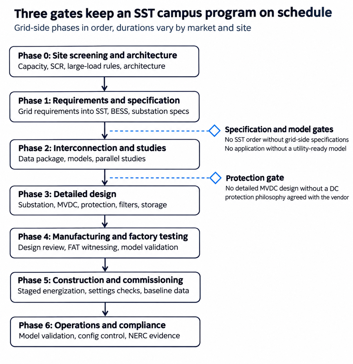
Figure 2. SST campus grid-side roadmap · 7 phases, 3 gates
The gates sit early: two at the end of specification, one before detailed design. That is where a missed requirement is still cheap to fix.
- Phase 0: Site screening and architecture (before land commitment). Screen candidate sites for available capacity, short-circuit strength, likely upgrades and large-load rules. Set the preliminary power architecture: interconnection voltage, MV level, MVDC voltage, storage roles and onsite generation. Identify NERC applicability for each architecture option.
- Phase 1: Requirements and specification. Write the grid-side requirements into the SST, storage and substation specifications: ride-through, reactive capability, harmonic limits, fault behavior, insulation, models and tests. Select or confirm the SST supplier or development partner with those requirements in hand.
- Phase 2: Interconnection application and studies. Submit the large-load application with the full data package, including preliminary EMT and positive-sequence models. Run independent studies in parallel with the utility's, so issues are found early. Respond to utility study results and negotiate upgrades.
- Phase 3: Detailed design. Complete the substation, transmission, MV collector and MVDC designs. Finish the protection philosophy, arc flash, grounding and insulation coordination studies. Size filters and storage. Update models as the SST design matures.
- Phase 4: Manufacturing and factory testing. Review vendor designs, witness factory acceptance tests, validate models against test results, and manage quality across the production run.
- Phase 5: Construction and commissioning. Verify installation, protection settings and grounding. Energize in stages with power quality monitoring. Perform site performance tests and capture baseline data.
- Phase 6: Operations and compliance. Validate models against recorded disturbances, maintain configuration control of firmware and settings, prepare NERC evidence, and support expansion phases.
Gates that protect the schedule
Three gates do most of the work of keeping an SST program on schedule:
- Model gate. No interconnection application without an EMT and positive-sequence model that meets the utility's requirements. A missing or poor model is the single largest source of study delay.
- Specification gate. No SST purchase order without grid-side performance written into the specification and test plan. Requirements added after the order are change orders.
- Protection gate. No detailed MVDC design without an agreed protection philosophy for DC faults, including the interface with SST internal protection. Protection decisions drive equipment selection, layout and the arc flash results.
One integrated team
The value of an integrated grid-side partner is that the same team holds the interconnection, the studies, the design, the compliance program and the owner's engineering. Decisions in one area are checked against the others as they are made, not months later. That is the model Keentel offers, with each discipline led by experienced engineers and supported by qualified partners where specialist tools or capacity are needed.
Worked examples: first-pass numbers for an SST campus
Screening numbers settle many early decisions before any detailed study starts. The five examples below use round, illustrative values to show the order of magnitude of each problem. They are simplified hand calculations, not substitutes for the studies described above, and every value should be replaced with site and vendor data.
Example 1: short-circuit ratio at the point of interconnection
Assume a 1,000 MW SST campus connects to a 345 kV bus. The utility reports a three-phase fault current of 20 kA with all lines in service and 12 kA with the most critical line out of service. The SSTs are rated about 1,050 MVA in total.
The available short-circuit power is:
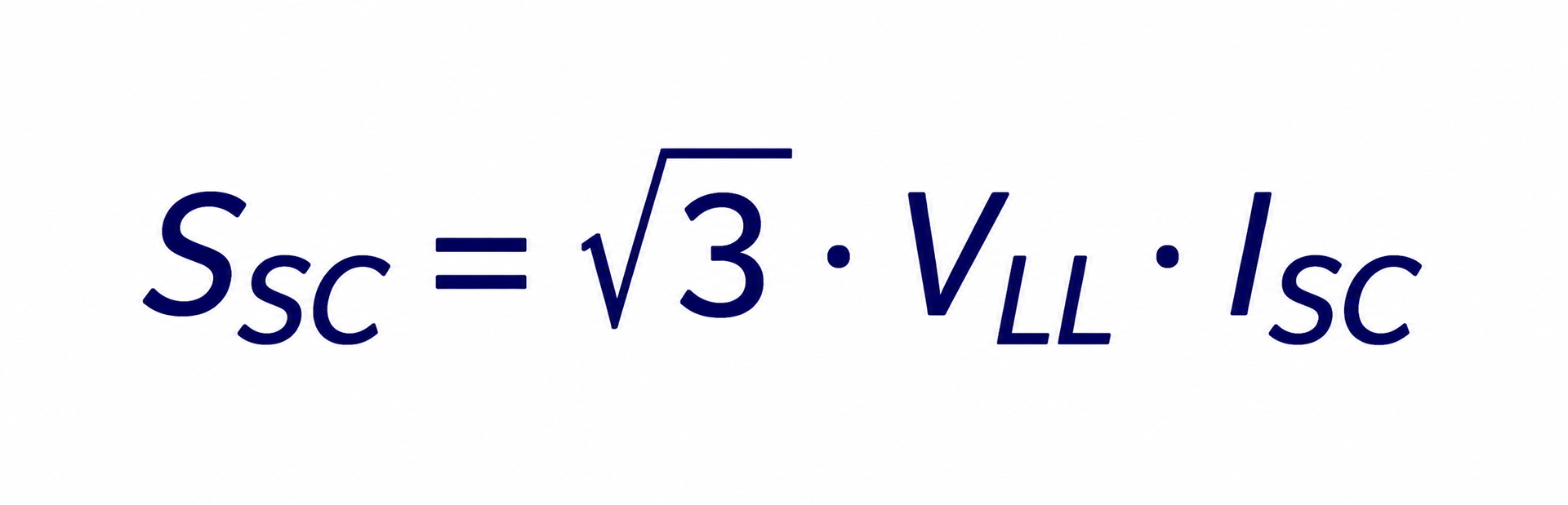
- All lines in service: √3 × 345 kV × 20 kA ≈ 11,950 MVA, so SCR ≈ 11,950 / 1,050 ≈ 11.4.
- Critical line out: √3 × 345 kV × 12 kA ≈ 7,170 MVA, so SCR ≈ 7,170 / 1,050 ≈ 6.8.
Those values look comfortable. Now add 800 MW of nearby solar and wind plants that share the same electrical area. A simple composite screen divides the fault level by the total converter rating in the area: 7,170 / (1,050 + 800) ≈ 3.9. Weighted methods such as ERCOT's weighted short-circuit ratio account for the electrical distance between plants and can give a different answer, but the direction is the same. Many planners treat values approaching 3 or below as weak-grid conditions that require detailed EMT analysis. Screening thresholds vary by utility.
The lesson: a strong 345 kV bus can still be a weak point for a gigawatt of converters once outages and neighbouring inverter-based plants are counted.
Example 2: transformer impedance and SCR at the MV bus
The SSTs connect at medium voltage, so the transformer impedance sits between them and the grid. Assume 345/34.5 kV main transformers rated 300 MVA, each feeding about 250 MW of SSTs. Treat the system as the 7,170 MVA outage case from Example 1 and ignore the loading from other transformers, which makes this an optimistic first pass.
- At 12% impedance, the transformer limits through-fault power to 300 / 0.12 = 2,500 MVA. In series with the system, the MV bus sees about 1 / (1/7,170 + 1/2,500) ≈ 1,850 MVA. SCR at the MV bus ≈ 1,850 / 262 ≈ 7.1.
- At 9% impedance, the transformer limit is 300 / 0.09 ≈ 3,330 MVA, and the MV bus sees about 2,275 MVA. SCR ≈ 8.7.
Lower impedance raises system strength at the SST terminals, which helps converter control stability. It also raises MV fault duty and arc flash energy. Impedance is therefore a trade-off between the EMT study and the MV equipment and safety studies, and should be chosen with both in view.
Example 3: IEEE 519 current limits at a 345 kV point of interconnection
For the same 1,000 MW campus at 345 kV and a power factor near unity, the maximum demand current is about:
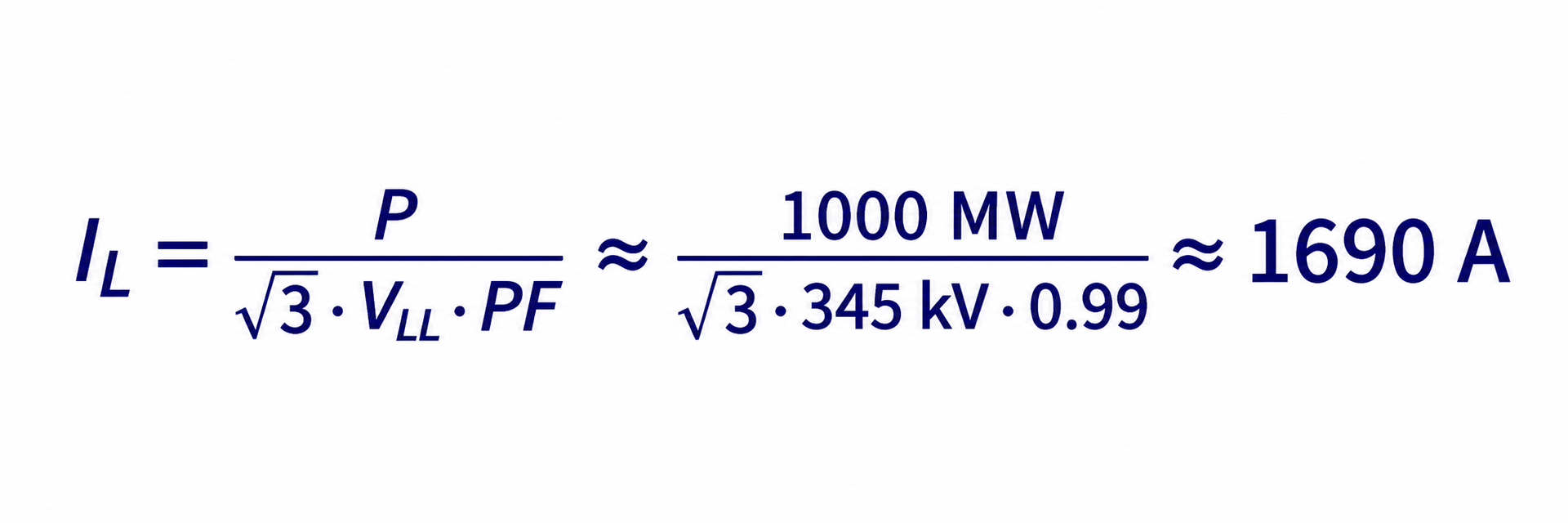
With 20 kA of available fault current, ISC/IL ≈ 20,000 / 1,690 ≈ 11.8. For systems above 161 kV, that falls in the lowest ISC/IL band of IEEE 519-2022, which carries the tightest limits: on the order of 1.0% of IL for individual harmonics below the 11th order and 1.5% total demand distortion. Confirm the exact values against the current table in the standard and the utility's requirements.
At 1.0%, the allowed current for each low-order harmonic is roughly 17 A at the point of interconnection, for a campus drawing about 1,690 A of fundamental current. A few hundred SST modules, each with low distortion, can approach that level once their emissions add and any network resonance amplifies them. That is why the harmonic study in Section 4 matters even for clean converters.
Example 4: DC bus capacitor discharge into a fault
Assume an illustrative MVDC bus section at 6 kV DC with 20 converters connected, each with 2 mF of DC-link capacitance. Total capacitance is 40 mF and the stored energy is:
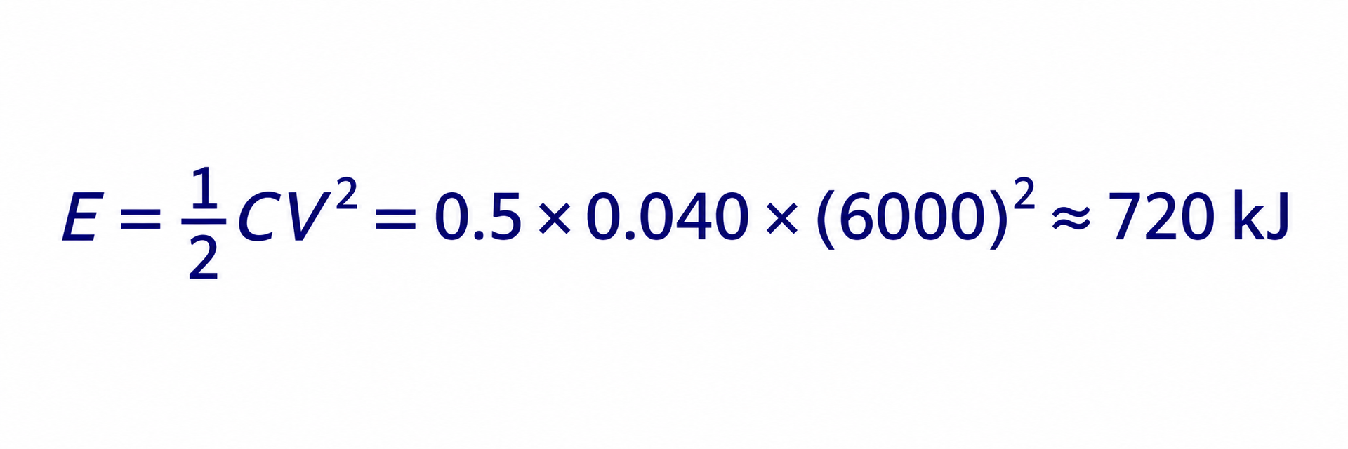
If a bolted pole-to-pole fault occurs with 20 µH of loop inductance and negligible resistance, the undamped peak current and time to peak are approximately:
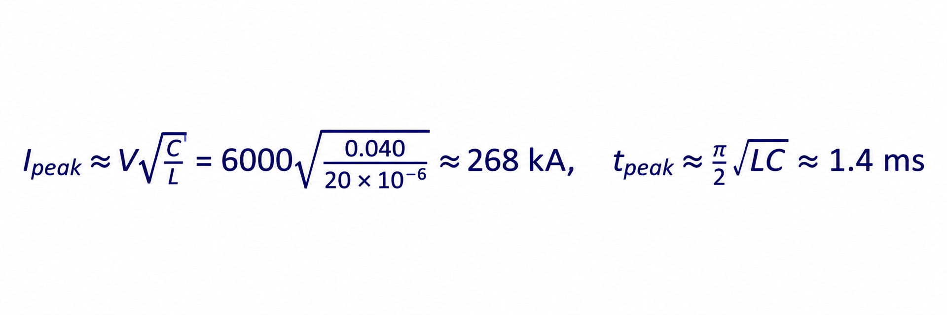
Real circuits have resistance, distributed capacitance and converter-side impedance that reduce this figure considerably. But even as an upper bound, it shows why DC protection must act in milliseconds or less, why fault location must be fast, and why the converters' own protection may trip before external devices can respond. It also shows why the DC arc flash assessment must account for stored capacitor energy, not just steady-state fault current.
Example 5: storage sizing is driven by role
The same battery serves very different duties depending on its role:
| Role | Illustrative duty | Energy needed | What sizes the system |
|---|---|---|---|
| Ride-through | Carry 500 MW for 2 s during a grid fault | 1,000 MJ ≈ 0.28 MWh | Power rating and converter current |
| Load smoothing | Absorb a ±100 MW swing at 0.5 Hz | About 64 MJ ≈ 18 kWh per half cycle | Power rating and cycle life |
| Peak shaving or curtailment | Replace 200 MW of grid supply for 4 h | 800 MWh | Energy capacity |
Ride-through and smoothing need high power and very little energy. Peak shaving and curtailment need large energy. A battery sized only for ride-through will not support emergency curtailment, and one sized for curtailment may need extra converter capacity to deliver ride-through current. Defining the roles first prevents sizing the wrong system.
SST vendor data request checklist
Most grid-side delays trace back to data the SST supplier was never asked to provide. The checklist below lists what the grid-side team needs from the supplier, why it is needed, and the latest phase by which it should arrive. It works equally well for an external vendor, a development partner or an in-house SST team. Write it into the purchase or development agreement.
| Data item | Used for | Needed by |
|---|---|---|
| Ratings: MV input voltage and range, frequency range, rated and overload power, DC output voltage and regulation | Architecture, substation and MV design, load flow | Phase 0 |
| Ride-through capability curves for voltage, frequency, rate of change of frequency and phase jump | Interconnection application, NERC applicability, specification | Phase 1 |
| Reactive power capability across voltage and power range | Load flow, reactive compensation sizing | Phase 1 |
| AC fault current contribution profile, balanced and unbalanced, with control mode | Short-circuit and utility protection studies | Phase 2 |
| DC fault current contribution, DC-link capacitance, blocking time | DC short-circuit, protection philosophy, arc flash | Phase 2 |
| Internal protection functions, thresholds, time delays and settings ranges | Protection coordination, ride-through verification | Phase 2 |
| Positive-sequence dynamic model with documentation and parameters | Utility stability studies | Phase 2 |
| EMT model with actual control code, user guide and benchmark results | EMT studies, utility model acceptance | Phase 2 |
| Harmonic, interharmonic and supraharmonic emission spectra across load levels | Harmonic study, filter design, IEEE 519 compliance | Phase 2 |
| Frequency-dependent output impedance of the AFE | Resonance and control interaction studies | Phase 2 |
| Inrush and energization behaviour | Energization studies, MV protection settings | Phase 3 |
| Insulation levels, basic insulation level, DC withstand, partial discharge limits | Insulation coordination, cable and switchgear specification | Phase 3 |
| Grounding requirements and compatibility with MV and MVDC grounding schemes | Grounding design, protection | Phase 3 |
| Enclosure arc rating, accessible energized parts, maintenance procedures | Arc flash study, safety procedures | Phase 3 |
| Control modes and interfaces: setpoints, ramp rates, smoothing, curtailment, communications | Campus control design, market participation | Phase 3 |
| Losses and efficiency curves, heat rejection | Thermal design, energy accounting | Phase 3 |
| Reliability data: MTBF, MTTR, redundancy, failure modes and effects | Reliability analysis, spare strategy | Phase 3 |
| Product safety certification path and field evaluation plan | Authority having jurisdiction approval | Phase 3 |
| Factory and type test reports, including grid performance and model validation tests | Owner's acceptance, utility package | Phase 4 |
| Firmware version control and change notification process | Model management, NERC evidence | Phase 4 |
Two rules make the list work. First, every item should have a contractual delivery date tied to the program schedule. Second, every model and setting delivered should carry a firmware version, so that what the utility studied can be traced to what is installed.
Questions to ask in the first technical meeting
A first meeting between an SST developer and a grid-side engineering team goes faster with a short list of questions. These are the ones that shape scope and schedule most:
- Architecture. What MV input voltage and DC output voltage are targeted? Is there a campus MVDC bus, an LVDC bus, or both? What is the module rating and how many modules per campus?
- Sites and markets. Which sites come first, in which markets, and at what stage is each interconnection request?
- Utility requests. Has any utility asked for EMT models, ride-through commitments or harmonic studies yet? What did it ask for, and by when?
- Topology and fault behaviour. Which topology is the design converging on, and can the converters block quickly for DC faults? How does the AFE control negative-sequence current?
- Storage and generation. Is storage planned on the DC bus? For which roles? Can the campus export power?
- Protection philosophy. Has a DC protection approach been chosen? Which devices are under consideration?
- Models. What simulation models exist today, in which tools, and can they be packaged for utility use with the actual control code?
- Testing. What test facilities are available for full-power, grid-simulator and hardware-in-the-loop testing?
- Build or partner. Which parts of the grid-side work does the team intend to hold internally, and where does it want an outside partner?
- Schedule. What is the target energization date for the first site, and what are the long-lead items?
Keentel services for SST and MVDC data center programs
Keentel Engineering covers the grid side of an SST campus end to end, from site screening to NERC compliance, and leaves the converter hardware to the SST designers. We are an electrical power systems and grid interconnection firm with study capability from 4 kV to 765 kV and a service line built specifically for data center power. Our role on an SST program is to make sure the grid, the substation, the MVDC system and the regulators all accept what the SST team builds.
What we deliver
| Service area | What we do for SST campuses | Typical deliverables |
|---|---|---|
| Grid interconnection | Site screening, large-load applications, independent studies, utility and RTO coordination in ERCOT, NYISO, PJM and other markets | Screening reports, application data packages, load flow, contingency and stability studies, study review memos |
| EMT modeling | Model requirements, vendor model review, campus aggregation, ride-through, weak-grid, control interaction and load-oscillation studies | EMT model specifications, model acceptance reports, PSCAD study reports, SCR screening |
| MV/MVDC system studies | AC and DC short-circuit, DC protection philosophy, AC protection, arc flash, grounding, insulation coordination | Study reports, protection philosophy documents, settings files, arc flash labels, interface control documents |
| Power quality | Emission requirements, frequency scans, IEEE 519-2022 compliance, filter sizing, flicker assessment | Harmonic study reports, filter specifications, monitoring plans |
| Substation and transmission design | HV/EHV substations, MV collectors, transmission lines, utility interface protection | Physical and electrical drawing packages, specifications, bills of material, protection and control design |
| NERC compliance | Registration and applicability, ride-through requirements, model validation, monitoring, compliance programs | Applicability assessments, compliance programs, evidence packages, model validation reports |
| Owner's engineer and QA/QC | SST, storage and substation specifications, design reviews, FAT and SAT plans and witnessing, multi-unit QA | Specifications, review comments, test plans, witness reports, due diligence reports |
| Onsite generation and BESS | Role definition and sizing, DC bus control architecture, fire and code compliance coordination, performance testing | Sizing studies, control architecture documents, specifications, test procedures |
Study platforms
Our studies are delivered on the platforms utilities and RTOs expect, including PSCAD/EMTDC, Siemens PTI PSS®E, GE PSLF, DIgSILENT PowerFactory, ASPEN OneLiner and ETAP, through our engineering team and qualified study partners.
How we engage
- Program partner. One integrated grid-side team across all eight areas, from site screening to operations.
- Targeted studies. A defined study or design package, such as an EMT study, a harmonic study or a DC protection philosophy.
- Owner's engineer. Independent technical representation of the owner through specification, procurement, testing and commissioning.
- Technical due diligence. Independent review of SST campus designs, interconnection positions and compliance risk for investors and lenders.
- Vendor support. Grid-side support for SST manufacturers preparing models, test plans and documentation that utilities will accept.
What we do not do
We do not design SST power electronics, magnetics or converter control firmware. We work alongside the teams that do, and we define, check and verify the system requirements at their boundary. Civil, structural and geotechnical design is coordinated with licensed specialists. CIP cyber security is coordinated with the owner's cyber team.
Firm facts
Keentel LLC, doing business as Keentel Engineering, is headquartered in Tampa, Florida, with offices in Austin, Sacramento and Baltimore. We are NSPE members, D-U-N-S registered, IEEE Senior Member-led and BBB A+ accredited. PE licensure is held across our active markets, and we will say before contract if a state license is not held.
Start a scope: (813) 389-7871 · contact@keentelengineering.com ·
| Office | Address | Phone |
|---|---|---|
| Tampa (Head Office) | 400 N Ashley Dr STE #2600, Tampa, FL 33602 | (813) 389-7871 |
| Austin | 5900 Balcones Drive STE 100, Austin, TX 78731 | (512) 591-0752 |
| Sacramento | 1401 21st St Ste R, Sacramento, CA 95811 | (916) 913-4524 |
| Baltimore | 306 W Redwood St STE 200, Baltimore, MD 21201 | (410) 225-2181 |
Case study A: a 600 MW SST campus in ERCOT
Illustrative scenario. This is an anonymized composite written to show how the grid-side work fits together on an SST campus. It is not a description of a specific client project, and the figures are representative.
The client. An AI infrastructure developer planning a 600 MW first phase of a campus in Texas, with a path to more than 1 GW. The power architecture used MV SSTs fed from a new 345/34.5 kV substation, a campus MVDC distribution bus and 800 VDC rack power. A battery system on the MVDC bus was planned for ride-through.
The challenge. The developer had a site, a utility relationship and an SST development partner, but the large-load application had stalled. The transmission service provider had asked for dynamic and EMT models, ride-through commitments, a harmonic assessment and details of backup generation and curtailment capability under the new Texas large-load requirements. The SST partner had detailed internal simulation models but nothing packaged for utility use. No one owned the question of how the campus would behave as a whole.
What the grid-side team did
- Short-circuit ratio screening. A screening study of the 345 kV interconnection bus showed adequate system strength with all lines in service. Under the worst single line outage, combined with nearby solar and wind plants counted as inverter-based, the effective SCR at the campus fell into a range where converter control stability could not be assumed. That finding moved weak-grid performance from a later-phase concern to a design input.
- Specification of grid performance. The team wrote a grid-side performance annex for the SST development agreement. It covered ride-through curves aligned with the utility's requirements and the developer's chosen margin, reactive capability, stable operation down to a defined minimum SCR, harmonic and supraharmonic emission limits, and EMT model delivery with the actual control code.
- Model packaging and acceptance. Working with the SST partner, the team defined the model deliverable, ran the utility's benchmark tests on early versions, and documented the issues. Several rounds were needed before the model initialized cleanly and behaved consistently at the utility's time step.
- Campus EMT studies. Using an aggregated campus model, the team ran ride-through, weak-grid, energization and load-oscillation studies. The weak-grid cases at the lowest SCR showed a poorly damped oscillation. The SST partner adjusted control parameters, and a lower-impedance specification for the main power transformers raised the effective SCR. Both changes together restored margin.
- Storage roles redefined. The studies showed the planned battery was large enough to smooth the AI workload swings as well as provide ride-through. The developer added smoothing as a defined role, which addressed the utility's concern about periodic power swings at the point of interconnection.
- Harmonic assessment. Frequency scans of the 34.5 kV cable collector system identified a parallel resonance near a frequency where the SST interleaving was weakest. Revised interleaving and a damped filter on two collector buses kept projected emissions within IEEE 519-2022 limits.
- NERC and market positioning. An applicability assessment confirmed that, as long as the battery could not export to the grid, the campus would not register as an inverter-based generator owner. The team documented that boundary and the design controls that enforce it. The curtailment and remote-disconnect provisions were addressed through the storage-backed flexibility.
What the scenario illustrates
- Weak-grid risk found at the screening stage cost a specification change. Found after equipment order, it would have meant a redesign.
- The single most schedule-critical deliverable was the utility-ready EMT model, not any study result.
- Storage on the MVDC bus did more for the interconnection case when its roles were defined with the grid studies in view.
- Writing grid-side requirements into the SST development agreement gave the developer leverage it would not otherwise have had.
Case study B: DC protection and factory testing for a New York SST deployment
Illustrative scenario. This is an anonymized composite written to show the owner's engineering and MVDC protection work on an SST program. It is not a description of a specific client project, and the figures are representative.
The client. An owner converting part of a large New York data center campus to SST-fed MVDC distribution for a new AI hall of about 250 MW. The campus connected at 115 kV, with an existing 13.8 kV distribution system. The owner was buying SST modules from an early-stage supplier, with batteries and DC/DC converters from other suppliers on the same MVDC bus.
The challenge. Three suppliers each had their own protection logic inside their equipment. Nobody had defined how a DC fault on the bus would be detected, located and cleared, or how the suppliers' internal protections would coordinate. The supplier's factory test plan covered efficiency, temperature rise and functional tests, but not grid performance, fault behavior or model validation. The utility had asked for ride-through and harmonic data for the new hall.
What the grid-side team did
- Interface control document. The team wrote an interface control document defining, for each supplier, what it must deliver at the MVDC bus: fault current contribution profiles, blocking times, internal protection thresholds and timing, grounding compatibility, insulation levels and communication interfaces.
- DC fault study. EMT simulation of pole-to-pole and pole-to-ground faults at several bus locations showed that capacitor discharge from all converters, plus the battery converters' current limits, produced a peak current well above what the originally selected DC switchgear could interrupt selectively. Without changes, any bus fault would have tripped every converter on the bus.
- Protection philosophy. The team developed a philosophy combining fast converter blocking, sectionalizing with solid-state switching at the bus sections, and coordinated time margins so that supplier internal protection acted as backup rather than primary. The grounding scheme was changed to high-resistance midpoint grounding with insulation monitoring, allowing continued operation through a first pole-to-ground fault. Cable and busway insulation levels were confirmed for the resulting pole-to-ground voltage.
- Arc flash. DC arc flash calculations for the MVDC switchgear and the 800 VDC distribution, using conservative published methods, informed equipment selection, remote operation and maintenance procedures.
- Factory acceptance test plan. The team expanded the SST factory test plan to include partial discharge measurements on the medium-frequency transformers, ride-through tests on a grid simulator at the highest power available, fault response and blocking-time tests, harmonic emission measurements, and model validation comparing recorded results with the EMT model. Hardware-in-the-loop tests of the controller covered weak-grid and fault cases that the factory could not produce.
- Witnessing and findings. At the factory test, partial discharge measurements on early production units exceeded the agreed limit at elevated test voltage. The supplier traced the issue to an insulation process step and corrected it before volume production. Model validation showed a difference in post-fault recovery timing, which the supplier corrected in the model.
- Utility package. The validated model, ride-through results and harmonic measurements formed the data package for the utility's review of the new hall.
What the scenario illustrates
- With multiple suppliers on one DC bus, the protection system has to be designed at the system level. Each supplier's protection only protects its own equipment.
- A factory test plan written for grid-side performance finds problems that a product test plan does not.
- A model validated at the factory gives the utility confidence and shortens review.
- Grounding choices for MVDC affect protection, insulation and continuity of service together, and should be made once, with all three in view.
Case study A: a 600 MW SST campus in ERCOT
Illustrative scenario. This is an anonymized composite written to show how the grid-side work fits together on an SST campus. It is not a description of a specific client project, and the figures are representative.
The client. An AI infrastructure developer planning a 600 MW first phase of a campus in Texas, with a path to more than 1 GW. The power architecture used MV SSTs fed from a new 345/34.5 kV substation, a campus MVDC distribution bus and 800 VDC rack power. A battery system on the MVDC bus was planned for ride-through.
The challenge. The developer had a site, a utility relationship and an SST development partner, but the large-load application had stalled. The transmission service provider had asked for dynamic and EMT models, ride-through commitments, a harmonic assessment and details of backup generation and curtailment capability under the new Texas large-load requirements. The SST partner had detailed internal simulation models but nothing packaged for utility use. No one owned the question of how the campus would behave as a whole.
What the grid-side team did
- Short-circuit ratio screening. A screening study of the 345 kV interconnection bus showed adequate system strength with all lines in service. Under the worst single line outage, combined with nearby solar and wind plants counted as inverter-based, the effective SCR at the campus fell into a range where converter control stability could not be assumed. That finding moved weak-grid performance from a later-phase concern to a design input.
- Specification of grid performance. The team wrote a grid-side performance annex for the SST development agreement. It covered ride-through curves aligned with the utility's requirements and the developer's chosen margin, reactive capability, stable operation down to a defined minimum SCR, harmonic and supraharmonic emission limits, and EMT model delivery with the actual control code.
- Model packaging and acceptance. Working with the SST partner, the team defined the model deliverable, ran the utility's benchmark tests on early versions, and documented the issues. Several rounds were needed before the model initialized cleanly and behaved consistently at the utility's time step.
- Campus EMT studies. Using an aggregated campus model, the team ran ride-through, weak-grid, energization and load-oscillation studies. The weak-grid cases at the lowest SCR showed a poorly damped oscillation. The SST partner adjusted control parameters, and a lower-impedance specification for the main power transformers raised the effective SCR. Both changes together restored margin.
- Storage roles redefined. The studies showed the planned battery was large enough to smooth the AI workload swings as well as provide ride-through. The developer added smoothing as a defined role, which addressed the utility's concern about periodic power swings at the point of interconnection.
- Harmonic assessment. Frequency scans of the 34.5 kV cable collector system identified a parallel resonance near a frequency where the SST interleaving was weakest. Revised interleaving and a damped filter on two collector buses kept projected emissions within IEEE 519-2022 limits.
- NERC and market positioning. An applicability assessment confirmed that, as long as the battery could not export to the grid, the campus would not register as an inverter-based generator owner. The team documented that boundary and the design controls that enforce it. The curtailment and remote-disconnect provisions were addressed through the storage-backed flexibility.
What the scenario illustrates
- Weak-grid risk found at the screening stage cost a specification change. Found after equipment order, it would have meant a redesign.
- The single most schedule-critical deliverable was the utility-ready EMT model, not any study result.
- Storage on the MVDC bus did more for the interconnection case when its roles were defined with the grid studies in view.
- Writing grid-side requirements into the SST development agreement gave the developer leverage it would not otherwise have had.
Case study B: DC protection and factory testing for a New York SST deployment
Illustrative scenario. This is an anonymized composite written to show the owner's engineering and MVDC protection work on an SST program. It is not a description of a specific client project, and the figures are representative.
The client. An owner converting part of a large New York data center campus to SST-fed MVDC distribution for a new AI hall of about 250 MW. The campus connected at 115 kV, with an existing 13.8 kV distribution system. The owner was buying SST modules from an early-stage supplier, with batteries and DC/DC converters from other suppliers on the same MVDC bus.
The challenge. Three suppliers each had their own protection logic inside their equipment. Nobody had defined how a DC fault on the bus would be detected, located and cleared, or how the suppliers' internal protections would coordinate. The supplier's factory test plan covered efficiency, temperature rise and functional tests, but not grid performance, fault behavior or model validation. The utility had asked for ride-through and harmonic data for the new hall.
What the grid-side team did
- Interface control document. The team wrote an interface control document defining, for each supplier, what it must deliver at the MVDC bus: fault current contribution profiles, blocking times, internal protection thresholds and timing, grounding compatibility, insulation levels and communication interfaces.
- DC fault study. EMT simulation of pole-to-pole and pole-to-ground faults at several bus locations showed that capacitor discharge from all converters, plus the battery converters' current limits, produced a peak current well above what the originally selected DC switchgear could interrupt selectively. Without changes, any bus fault would have tripped every converter on the bus.
- Protection philosophy. The team developed a philosophy combining fast converter blocking, sectionalizing with solid-state switching at the bus sections, and coordinated time margins so that supplier internal protection acted as backup rather than primary. The grounding scheme was changed to high-resistance midpoint grounding with insulation monitoring, allowing continued operation through a first pole-to-ground fault. Cable and busway insulation levels were confirmed for the resulting pole-to-ground voltage.
- Arc flash. DC arc flash calculations for the MVDC switchgear and the 800 VDC distribution, using conservative published methods, informed equipment selection, remote operation and maintenance procedures.
- Factory acceptance test plan. The team expanded the SST factory test plan to include partial discharge measurements on the medium-frequency transformers, ride-through tests on a grid simulator at the highest power available, fault response and blocking-time tests, harmonic emission measurements, and model validation comparing recorded results with the EMT model. Hardware-in-the-loop tests of the controller covered weak-grid and fault cases that the factory could not produce.
- Witnessing and findings. At the factory test, partial discharge measurements on early production units exceeded the agreed limit at elevated test voltage. The supplier traced the issue to an insulation process step and corrected it before volume production. Model validation showed a difference in post-fault recovery timing, which the supplier corrected in the model.
- Utility package. The validated model, ride-through results and harmonic measurements formed the data package for the utility's review of the new hall.
What the scenario illustrates
- With multiple suppliers on one DC bus, the protection system has to be designed at the system level. Each supplier's protection only protects its own equipment.
- A factory test plan written for grid-side performance finds problems that a product test plan does not.
- A model validated at the factory gives the utility confidence and shortens review.
- Grounding choices for MVDC affect protection, insulation and continuity of service together, and should be made once, with all three in view.
Part D — Technical FAQ: Active Harmonic Filters
General
What is a solid-state transformer, in one sentence?
An SST is a power electronic converter that replaces a 60 Hz transformer and rectifier chain by converting medium-voltage AC to DC (or AC) through a high-frequency isolation stage, with its grid behavior set by control.
Does Keentel design solid-state transformers?
No. We do not design SST power electronics, magnetics or firmware. We engineer the grid side: interconnection, system studies, substations and transmission, protection, power quality, NERC compliance, owner's engineering and DC-coupled storage. We work alongside the SST designers and define the requirements at their boundary.
Why would an SST developer or AI campus owner need a separate grid-side firm?
Because the questions that decide whether an SST campus connects on time are system questions, not converter questions. The utility asks about ride-through, fault behavior, harmonics, models and compliance at the point of interconnection. Answering them takes power system studies, utility process experience and protection design that SST teams are not usually staffed for.
At what stage should we involve a grid-side engineer?
Before land commitment, if possible, and no later than the SST specification. Site screening for short-circuit strength and large-load rules, and writing grid requirements into the SST specification, are the two earliest and highest-value steps.
Interconnection and studies
Is an SST campus treated differently from a conventional data center in the interconnection process?
The process is generally the same large-load process. The technical review is more demanding, because the utility has to evaluate converter-driven behavior. Expect requests for EMT models, ride-through commitments and harmonic studies, in addition to the usual load flow and facilities studies.
Will the utility require PSCAD models?
Increasingly, yes, for large converter-interfaced loads. Many utilities and RTOs already require PSCAD models for inverter-based generation and are applying similar expectations to large loads. Even where it is not yet required, having a validated model shortens review.
What is short-circuit ratio and why does it matter for SSTs?
SCR is the ratio of the available short-circuit power at the connection point to the converter rating. Low SCR means a weak grid relative to the converter, and converter control can become unstable. A gigawatt of SSTs at one bus can produce a low SCR even on a strong transmission system, especially under outages.
Can SSTs help a campus get interconnected faster?
They can, if their capabilities are specified and proven. Reactive power support, ride-through, smoothing of AI workload swings and curtailment backed by storage all address concerns utilities have about large loads. The capability only counts once the utility accepts it in a model and study.
How do new Texas rules affect SST campuses?
Senate Bill 6 (2025) sets requirements for loads of 75 MW or more in ERCOT, including backup generation disclosure, financial commitments and curtailment or remote disconnection during emergencies. An SST campus with DC-side storage can often meet curtailment provisions without curtailing compute. Requirements are being implemented through rulemaking, so check current status at project start.
Faults, protection and safety
Why is DC protection harder than AC protection?
AC current crosses zero 120 times a second, which lets breakers interrupt it. DC current does not, so interruption needs solid-state or hybrid breakers, converter blocking or other methods. DC faults also start with very fast capacitor discharge, and selective protection must act within milliseconds or less.
How much fault current does an SST contribute?
On the AC side, usually about rated current, sometimes up to around 1.5 per unit briefly, set by control. On the DC side, the initial contribution from capacitors can be very large. Exact values come from the vendor and must be confirmed in studies.
Does IEEE 1584 cover DC arc flash?
No. IEEE 1584-2018 covers three-phase AC systems. DC arc flash is assessed with methods referenced in NFPA 70E's informative material, which are generally conservative and were developed mainly for batteries and lower voltages. MVDC arc flash needs careful engineering judgment.
How should an MVDC bus be grounded?
There is no single answer. Solid midpoint grounding gives clear fault detection but high fault current. High-resistance or floating schemes allow continued operation through a first ground fault but require insulation rated for pole voltage shifts and reliable insulation monitoring. The choice should be made with protection, insulation and continuity of service in view.
How do new Texas rules affect SST campuses?
Senate Bill 6 (2025) sets requirements for loads of 75 MW or more in ERCOT, including backup generation disclosure, financial commitments and curtailment or remote disconnection during emergencies. An SST campus with DC-side storage can often meet curtailment provisions without curtailing compute. Requirements are being implemented through rulemaking, so check current status at project start.
Power quality
Do SSTs cause harmonics?
They draw much cleaner current than traditional rectifiers, but at gigawatt scale, small emissions add up, and network resonances can amplify them. SSTs also emit at higher frequencies (supraharmonics) that IEEE 519 does not fully cover. A harmonic study at the point of interconnection is still needed.
Which standard sets harmonic limits?
In North America, IEEE 519-2022, applied at the point of common coupling, plus any stricter utility requirements. Measurements follow IEC 61000-4-7 and IEC 61000-4-30.
NERC and compliance
Are data centers subject to NERC standards?
Historically, end-use loads were not registered entities. NERC is now working on how large and computational loads should be modeled, registered and held to performance requirements. Several obligations already reach large loads through transmission owner interconnection requirements under FAC-001 and FAC-002. A campus with exporting storage or generation may register as an inverter-based resource owner.
What ride-through requirements will apply?
For loads, requirements are emerging through utility interconnection requirements, ERCOT revisions and NERC work. For exporting resources, PRC-024, PRC-029 and IEEE 2800-2022 apply. We recommend specifying SST ride-through to a defined, documented curve now, with margin for the requirements that are coming.
Storage and generation
Why put batteries on the MVDC bus instead of the AC side?
Fewer conversion stages, lower losses and less equipment, and the battery directly supports the bus that feeds the IT load. It can provide ride-through, smoothing, peak shaving and backup from one asset.
Does adding storage change NERC registration?
It can. If the campus can export power to the grid and the aggregate capacity meets NERC's inverter-based resource thresholds, the owner may need to register as a generator owner and operator. If export is prevented by design, that boundary should be documented.
Working with Keentel
Will Keentel share its study methods or tool configurations?
No. We deliver results, reports, models and documentation that meet utility and owner requirements. Our methodologies, workflows and tool configurations remain proprietary under all terms.
Can Keentel work with our SST vendor directly?
Yes. We regularly work with equipment suppliers under the owner's direction, defining requirements, reviewing models and designs, and witnessing tests, while representing the owner's interests.
How do we start?
Call (813) 389-7871, email contact@keentelengineering.com, or book a 15-minute call. A short scoping conversation is usually enough to define a first package, such as site screening or an SST grid-performance specification.
Glossary
| Term | Meaning |
|---|---|
| AFE | Active front end. The actively switched AC/DC stage of an SST that connects to the MV grid and sets its grid behavior. |
| Aggregated model | A model in which many converters are represented by a smaller number of equivalent converters to make campus-scale simulation practical. |
| Arc flash | The release of energy from an electric arc fault, assessed as incident energy at a working distance to set PPE and safe work practices. |
| BESS | Battery energy storage system. |
| Blocking | Turning off all converter switches so the converter stops feeding current, used to limit DC faults. |
| Composite load model | A positive-sequence load model that combines several load types, such as motors, electronics and static loads. |
| DAB | Dual active bridge. An isolated DC/DC converter topology with active bridges on both sides of a high-frequency transformer. |
| DC-link | The internal DC capacitor bank between converter stages. |
| EMT | Electromagnetic transient simulation. Time-domain simulation with microsecond time steps, used to study fast converter and network behavior. |
| FAT | Factory acceptance test. |
| Grid-forming | A converter control mode that sets its own voltage and frequency reference rather than following the grid's, providing support to weak grids. |
| HIL | Hardware-in-the-loop testing, in which a real controller is tested against a real-time simulation. |
| IBR | Inverter-based resource. Generation or storage connected to the grid through power electronics. |
| Insulation coordination | Matching the insulation strength of equipment to the voltage stresses the system produces, with surge protection where needed. |
| ISC/IL | The ratio of available short-circuit current to maximum demand load current at the point of common coupling, used to set IEEE 519 limits. |
| ISOP | Input-series, output-parallel. A modular converter arrangement that shares a high input voltage across cells in series and combines their outputs in parallel. |
| Large load | A load large enough to affect transmission system reliability. Definitions vary, for example 75 MW and above under Texas SB 6, or loads above 20 MW in the federal rulemaking proposal. |
| LVDC | Low-voltage DC, such as 800 VDC or ±400 VDC rack distribution. |
| MFT | Medium-frequency transformer. The compact isolation transformer inside an SST, operating at kilohertz frequencies. |
| MMC | Modular multilevel converter. A converter built from many submodules with their own capacitors, producing a stepped multilevel waveform. |
| MVDC | Medium-voltage DC distribution, roughly 1 kV to 35 kV DC in common usage. |
| OE | Owner's engineer. An independent engineer representing the owner's technical interests. |
| PCC / POI | Point of common coupling / point of interconnection, where the campus connects to the utility system and where compliance is usually assessed. |
| PLL | Phase-locked loop. The control element that tracks grid voltage phase and frequency. |
| Positive-sequence model | A fundamental-frequency, balanced dynamic model used in PSS®E, PSLF and similar tools. |
| Ride-through | The ability to stay connected and keep operating during and after a grid disturbance within defined limits. |
| SAT | Site acceptance test. |
| SCR | Short-circuit ratio. Available short-circuit power divided by converter rating, a measure of grid strength. |
| SiC | Silicon carbide, a wide-bandgap semiconductor material that allows higher voltage, higher frequency switching. |
| SST | Solid-state transformer. A power electronic converter with a high-frequency isolation stage that replaces a 60 Hz transformer and rectifier chain. |
| Supraharmonics | Emissions in the 2 kHz to 150 kHz range, above the range covered by most harmonic limits. |
| TDD | Total demand distortion. Harmonic current distortion relative to maximum demand current, used in IEEE 519. |
| WSCR | Weighted short-circuit ratio. An SCR screen that accounts for several inverter-based plants sharing a network area. |
References and further reading
Links were current at publication (November 2026). Large-load rules, NERC actions and standards editions are changing quickly, so confirm current versions before relying on them.
Large-load reliability and NERC
- NERC Publishes Incident Review and Guidance on Voltage-Sensitive Large Load Integration, NERC
- Reliability Insights: Large Computational Load Risks Due to Voltage Sensitivity, NERC, September 2026
- NERC Seeks to Address Reliability Impacts from Large Load Integration, NERC presentation to FERC, April 2025
- NERC issues Level 3 Alert to address immediate risks data center loads pose to the grid, Renewable Energy World, May 2026
- NERC Voltage-Sensitive Loads, Keentel Engineering
Federal and state large-load rules
- FERC Docket RM26-4, Interconnection of Large Loads, FERC
- FERC Establishes Proceeding to Consider DOE Directive on Large Load Transmission Interconnection Rulemaking, McGuireWoods, October 2025
- Texas Senate Bill 6 Ushers in Major Overhaul of Large Load Interconnection and Grid Access Rules, Bracewell, July 2025
- Public Utility Commission of Texas Issues Proposed Rules for Large Load Interconnections, Foley & Lardner, March 2026
Solid-state transformers and DC data center power
- Solid State Transformer project, Open Compute Project
- Novel Solid-State Transformer Supports 800-V DC Power in AI Data Centers, Electronic Design
- How SSTs are Reshaping Data Center Infrastructure, Microchip Technology
Standards referenced (consult the publisher for the current edition)
| Subject | Standard |
|---|---|
| Harmonics | IEEE 519-2022; IEC 61000-4-7; IEC 61000-4-30; IEC TR 61000-3-6 |
| Flicker | IEEE 1453 |
| Inverter-based resources | IEEE 2800-2022; IEEE 2800.2 |
| Arc flash and electrical safety | IEEE 1584-2018; NFPA 70E |
| Grounding | IEEE 80 |
| Insulation coordination | IEEE 1313.1; IEEE 1313.2; IEC 60071 |
| DC systems and short circuit | IEEE 1709 (MVDC on ships); IEC 61660; IEEE 946 |
| Converter safety | IEC 62477-1; IEC 62477-2 |
| Partial discharge | IEC 60270 |
| Energy storage | NFPA 855; UL 9540; UL 9540A; IEEE 2030.3 |
| Electrical installation | NFPA 70 (NEC); NESC |
| Testing and commissioning | ANSI/NETA ATS; ANSI/NETA ECS |
| NERC reliability standards | FAC-001; FAC-002; TPL-001; MOD-032; MOD-033; MOD-026-2; PRC-002; PRC-024; PRC-029; PRC-030; EOP-011 |
Disclaimer
General information only. This article is published for general technical and educational purposes. It is not engineering advice for any specific project, is not issued for construction, permitting or bidding, and carries no professional engineering seal or certification. Project decisions require a site-specific engagement and study.
Regulatory and standards currency. Large-load interconnection rules, NERC actions and standards, FERC proceedings, state legislation and industry standards referenced here were described as understood at the publication date and are changing. Readers should confirm current requirements with the applicable utility, RTO, NERC Regional Entity, regulator and standards body.
Case studies. The two case studies are anonymized, illustrative composites prepared to explain how grid-side work fits together. They do not describe a specific client project, and their figures are representative rather than measured results.
Outcomes outside our control. Interconnection approvals, study results, upgrade assignments, schedules and costs are determined by utilities, grid operators, regulators and authorities having jurisdiction. Nothing in this article is a guarantee of any outcome.
Scope and licensure. Keentel Engineering does not design solid-state transformer power electronics, magnetics or control firmware. Civil, structural and geotechnical work is coordinated with licensed specialists, and CIP cyber security is coordinated with the owner's cyber security team. Professional engineering services are provided only where Keentel holds the appropriate licensure, which we confirm before contract.
No reliance by third parties. This article creates no professional relationship or duty of care with any reader.
Trademarks and non-affiliation. PSCAD, PSS®E, PSLF, PowerFactory, ASPEN OneLiner, ETAP and other product names are trademarks of their respective owners. Companies, organizations and products named in this article are referenced for context only. Their mention does not imply affiliation with, endorsement of, or endorsement by Keentel Engineering.
State of Florida — Registry No. 36853, KEENTEL LLC, DBA: KEENTEL ENGINEERING. Copyright 1995-2026 Keentel Engineering. All Rights Reserved.

About the Author:
Sandip "Sonny" R. Patel, P.E.
IEEE Senior Member · Founder & CEO, Keentel Engineering
In 1995, Sonny Patel earned his Electrical Engineering degree from the University of Illinois. But degrees don't build legacies — action does.
For three decades, he has worked the power industry from every side of the table: 16 years as a utility engineer at Exelon/Commonwealth Edison; generation leadership across hydroelectric, industrial steam turbine, and a 9 GW renewable fleet; NERC Regional Entity Senior Compliance Engineer and Audit Team Lead, auditing some of the nation's largest utilities; and testing and commissioning lead on equipment up to 765 kV — the very top of the North American grid.Utility. Generator. Regulator. Consultant. Few engineers have seen all four seats. Fewer still have sat in them.
His experience spans nuclear, hydro, conventional generation, renewables, oil and gas, mining — and today's data centers, where he is authoring a three-book series on data center design. He is a Licensed Professional Engineer in six states and a Licensed Electrical Contractor in Florida (Unlimited EC) — he doesn't just design the work; he's qualified to stand behind its execution.Today, as Founder and CEO of Keentel Engineering, Sonny leads a nationwide team of engineers delivering substation design, power system studies, NERC compliance, and commissioning — done right, coast to coast.Three decades. Every side of the table. One standard: accountable engineering.
Services

Let's Discuss Your Project
Let's book a call to discuss your electrical engineering project that we can help you with.
About the Author:
Sandip "Sonny" R. Patel, P.E.
IEEE Senior Member · Founder & CEO, Keentel Engineering
In 1995, Sonny Patel earned his Electrical Engineering degree from the University of Illinois. But degrees don't build legacies — action does.
For three decades, he has worked the power industry from every side of the table: 16 years as a utility engineer at Exelon/Commonwealth Edison; generation leadership across hydroelectric, industrial steam turbine, and a 9 GW renewable fleet; NERC Regional Entity Senior Compliance Engineer and Audit Team Lead, auditing some of the nation's largest utilities; and testing and commissioning lead on equipment up to 765 kV — the very top of the North American grid.
Utility. Generator. Regulator. Consultant. Few engineers have seen all four seats. Fewer still have sat in them.
His experience spans nuclear, hydro, conventional generation, renewables, oil and gas, mining — and today's data centers, where he is authoring a three-book series on data center design. He is a Licensed Professional Engineer in six states and a Licensed Electrical Contractor in Florida (Unlimited EC) — he doesn't just design the work; he's qualified to stand behind its execution.
Today, as Founder and CEO of Keentel Engineering, Sonny leads a nationwide team of engineers delivering substation design, power system studies, NERC compliance, and commissioning — done right, coast to coast.Three decades. Every side of the table. One standard: accountable engineering.
Leave a Comment
Thank you for contacting us.
We will get back to you as soon as possible.
We will get back to you as soon as possible.
Oops, there was an error sending your message.
Please try again later.
Please try again later.
Related Posts
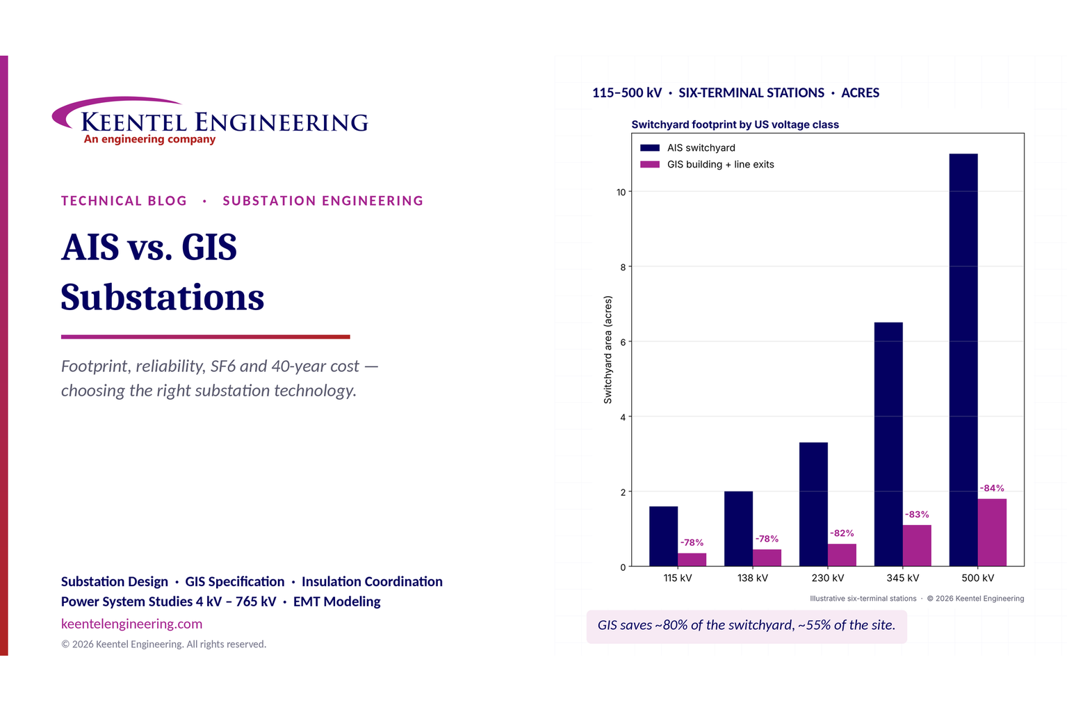
By SANDIP R PATEL
•
October 31, 2026
Compare AIS vs GIS substations by cost, footprint, reliability, maintenance and SF6 impact. Explore design differences and life-cycle costs for US substations.
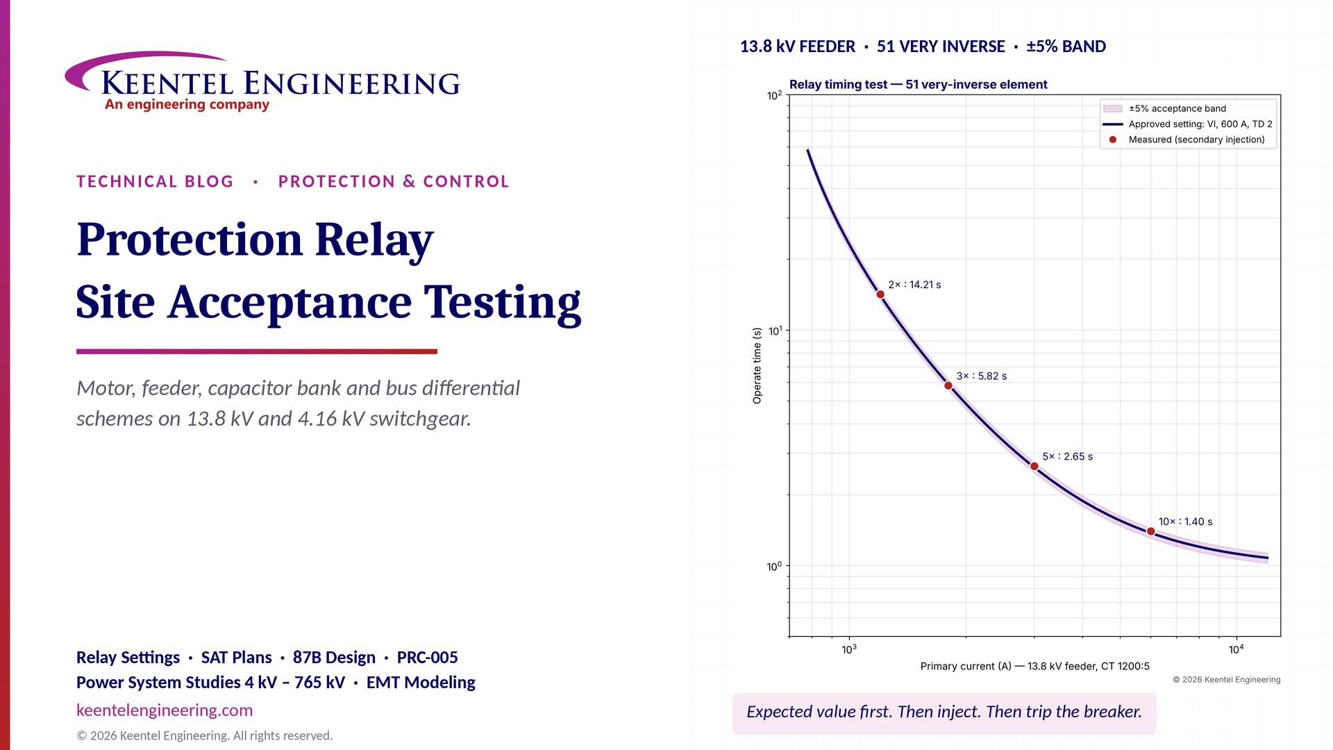
By SANDIP R PATEL
•
October 30, 2026
Protection relay site acceptance testing (SAT) guide covering CT/VT checks, secondary injection, motor relays, 87B bus differential and IEEE/NETA standards.

By SANDIP R PATEL
•
October 30, 2026
Understand SPP HILL requirements, HDPS interconnection studies, voltage and frequency ride-through, EMT modeling, weak-grid screening, and compliance.
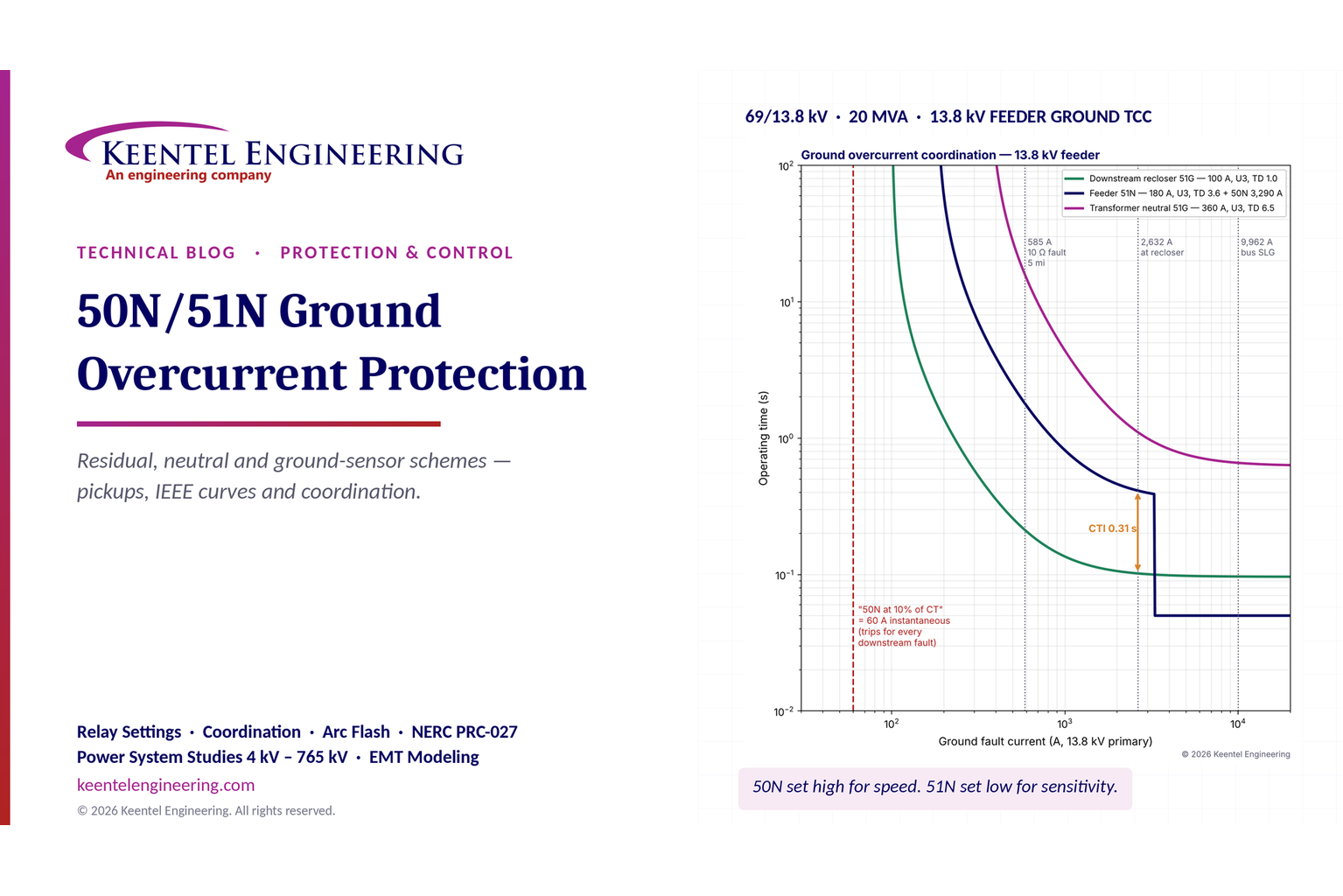
By SANDIP R PATEL
•
October 29, 2026
Learn 50N/51N ground overcurrent protection, relay settings, CT connections, IEEE curves, TCC coordination and ground fault protection for substations.
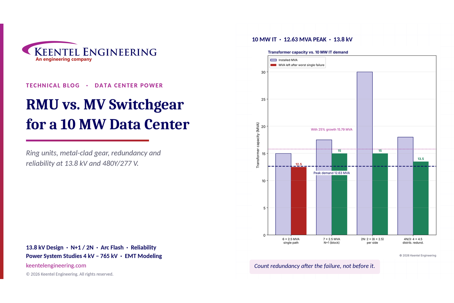
By SANDIP R PATEL
•
October 29, 2026
Compare RMU vs. MV switchgear for a 10 MW data center. Explore 13.8 kV design, transformer sizing, N+1/2N redundancy, arc flash and reliability.
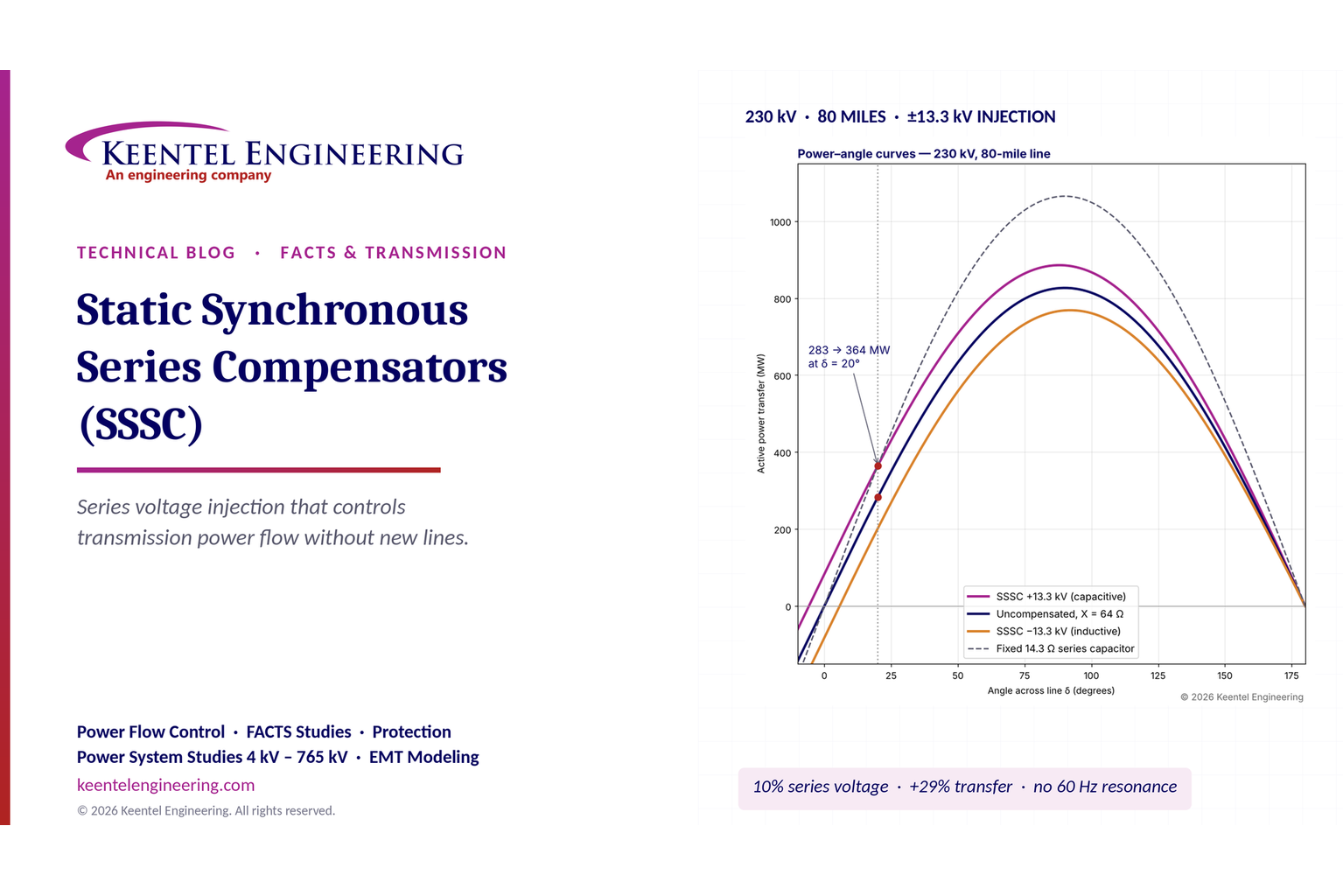
By SANDIP R PATEL
•
October 29, 2026
Learn how static synchronous series compensators (SSSC) control transmission power flow, improve grid stability and support FACTS applications, with examples.

By SANDIP R PATEL
•
October 28, 2026
Explore what's inside a data center rack, from servers and switches to PDU sizing, UPS, A/B redundancy, cooling and power design for high-density AI racks.
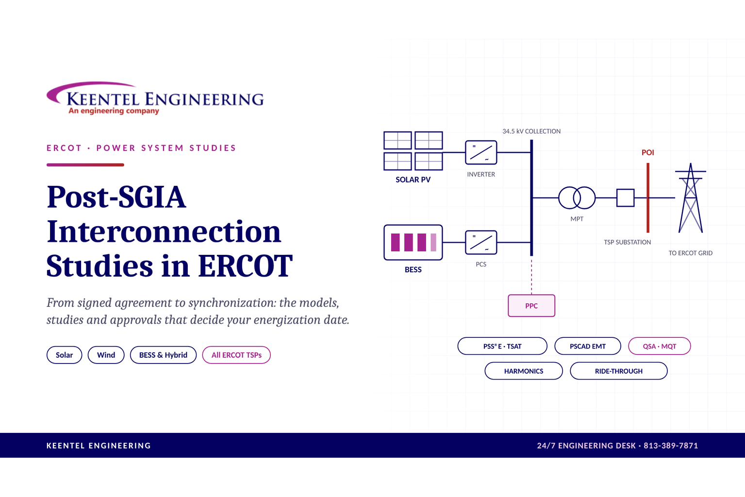
By SANDIP R PATEL
•
October 28, 2026
Explore post-SGIA interconnection studies in ERCOT, including PSCAD, PSS/E, QSA, model validation, TSP approvals and solar, wind and BESS commissioning.
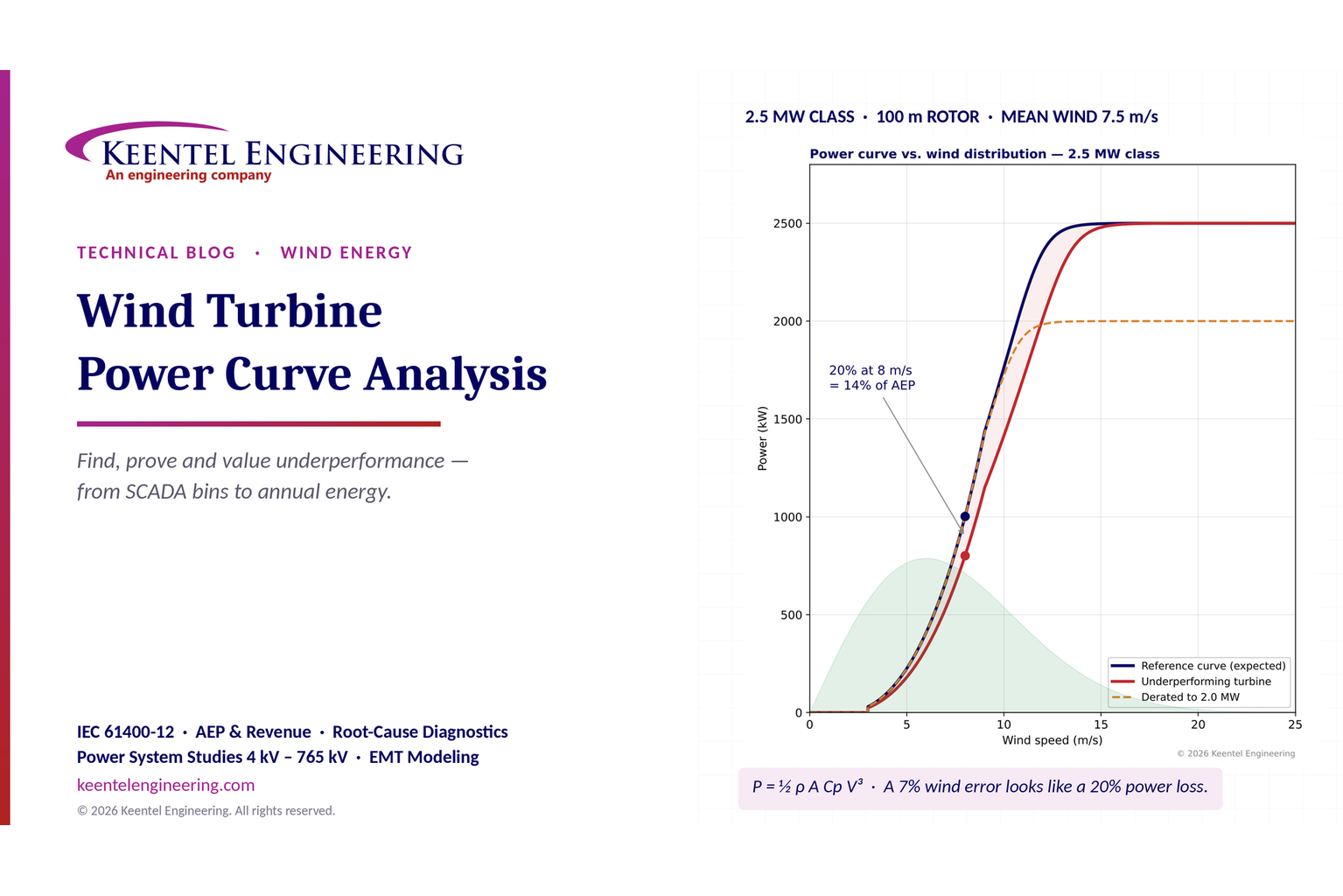
By SANDIP R PATEL
•
October 27, 2026
Learn wind turbine power curve analysis using SCADA data, IEC 61400-12, AEP calculations and diagnostics to identify underperformance and energy losses.