Part A — Ground Overcurrent Protection at a Glance
Single-line-to-ground faults are the most common faults on US transmission and distribution systems. On overhead lines they typically make up the large majority of all faults, driven by lightning, contamination, vegetation, animals and failed insulation. Protecting against them well is the difference between a feeder that clears a squirrel contact in a fraction of a second and one that burns down a conductor, damages a transformer or trips an entire substation.
Ground overcurrent protection is built from a small number of elements that are easy to name and surprisingly easy to misapply:
50N / 51N — instantaneous (50) and time (51) overcurrent elements operating on residual current, 3I0, usually calculated from three phase CTs.
50G / 51G — the same elements operating on current from a dedicated ground CT: either a CT in the transformer or generator neutral, or a ground-sensor (zero-sequence, core-balance) CT that encircles all three phase conductors.
67N / 67G — directional ground overcurrent, used where ground fault current can flow in both directions.
87N (restricted ground fault) — a differential ground element for transformer and generator windings.
59N / 64 — neutral or zero-sequence overvoltage, used on ungrounded and high-resistance-grounded systems where there is little or no ground fault current to measure.
This guide explains how these elements see a ground fault, how system grounding changes everything, how to connect the CTs correctly, how to choose pickups, curves and time dials using US conventions, and how to coordinate the ground elements in a substation from the 480 V service up to the 69 kV transformer.
The four ground sources a relay can measure
| Measurement | How it is obtained | What it sees | Practical minimum pickup | Typical device numbers |
|---|---|---|---|---|
| Residual (3I0) | Vector sum of three phase CTs, inside the relay or by paralleling CT secondaries | Ground current in the circuit, plus any CT error and load unbalance | About 10–20% of CT primary rating, and above normal neutral unbalance | 50N, 51N, 67N |
| Neutral CT | One CT in the transformer, generator or grounding-resistor neutral | Total ground current returning through that ground source, from every circuit it feeds | Limited by CT ratio and relay range; often 10–20% of NGR or neutral rating | 51G (neutral), 50G, 87N input |
| Ground-sensor (zero-sequence) CT | One window CT around all three phase conductors of a cable | Only ground current leaving that circuit; immune to phase-CT mismatch | A few amperes primary is achievable | 50G, 51G, 50GS |
| Zero-sequence voltage | Broken-delta VTs or calculated 3V0 | Ground faults on ungrounded or high-resistance-grounded systems | A few percent of normal phase voltage | 59N, 64 |
What Keentel's model shows
Keentel Engineering modeled a typical US suburban substation: a 69/13.8 kV, 20 MVA delta-wye transformer, solidly grounded on the 13.8 kV side, supplying a 13.8 kV overhead feeder with a line recloser 2 miles out. The 69 kV source was taken as 2,000 MVA.
| Quantity | Value |
|---|---|
| Three-phase fault at the 13.8 kV bus | 9.30 kA |
| Single-line-to-ground fault at the 13.8 kV bus (solidly grounded) | 9.96 kA |
| SLG fault at the recloser, 2 miles out | 2.63 kA |
| SLG fault at 5 miles, bolted / through 10 Ω | 1.24 kA / 585 A |
| SLG fault at the bus if the transformer is grounded through a 400 A resistor | 399 A |
| Line current on the 69 kV side for a 13.8 kV bus SLG fault | 1.15 kA in two phases, zero residual |
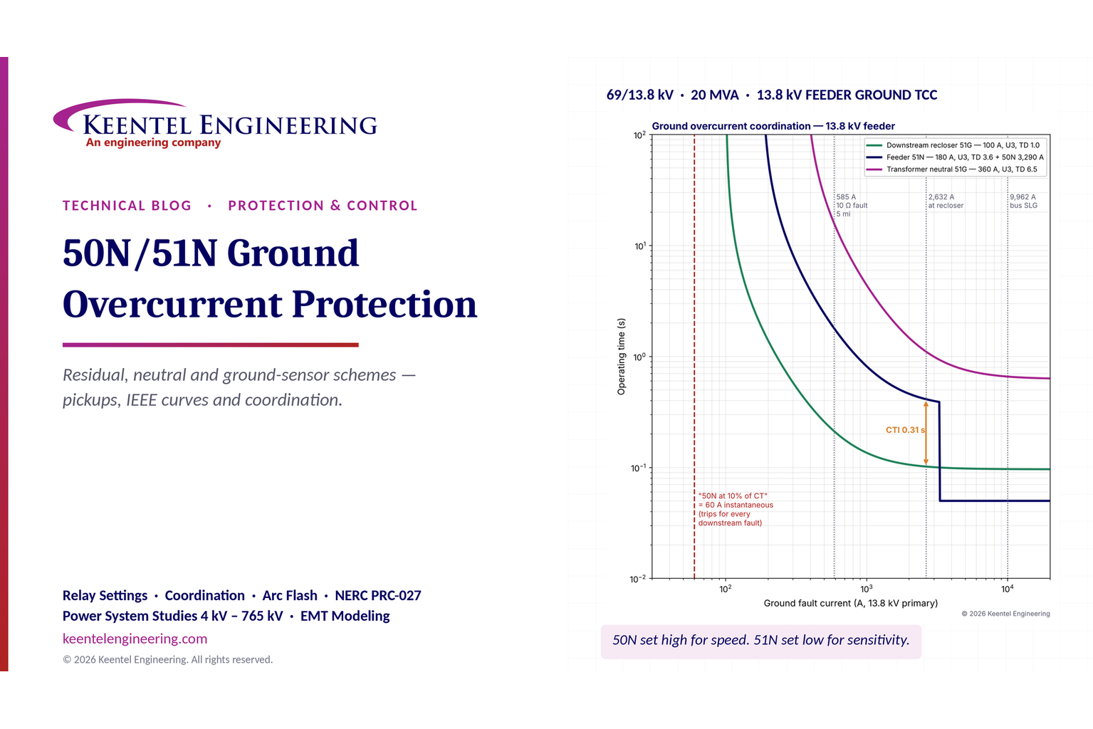
| Feeder 51N (180 A, U3, TD 3.6) versus recloser 51G (100 A, U3, TD 1.0) at 2.63 kA | 0.41 s vs 0.10 s — CTI 0.31 s |
| Feeder 50N setting (1.25 × max ground fault at the recloser) | 3,290 A, reaching about 1.5 miles |
| Transformer neutral 51G (360 A, U3, TD 6.5) versus feeder 51N at the bus fault | 0.66 s vs 0.35 s — CTI 0.31 s |
| False residual current from a 3% CT ratio mismatch during a 9.3 kA three-phase fault | About 280 A — more than the 51N pickup |

Figure 1. Keentel's ground coordination study for a 13.8 kV feeder supplied from a 69/13.8 kV, 20 MVA substation. A ground pickup set at "10% of CT rating" as an instantaneous element (dashed red) would trip the feeder breaker for every ground fault on the feeder, including faults the downstream recloser should clear.
Six lessons
Name the CT before you name the element. Residual, neutral and ground-sensor CTs measure different currents, have different error behavior and support very different pickups. Mixing them up is the root of many ground misoperations.
The instantaneous element is set high, not low. A 50N must stay out of the next downstream protective zone. Its pickup is set above the maximum ground fault current at the next device, with margin, not at a small percentage of the CT rating.
The time element provides sensitivity. The 51N or 51G is where sensitivity lives, with pickup above the worst normal unbalance and a time dial that coordinates with downstream devices.
System grounding decides the method. Solidly grounded, low-resistance-grounded, high-resistance-grounded and ungrounded systems need different protection. A delta winding blocks zero-sequence current, so the relays on one side of a delta-wye transformer do not see ground faults on the other side as ground faults.
US relays use US curves. IEEE C37.112 curve shapes and US-style time dials behave differently from the IEC "time multiplier setting" of 0.05–1.0. Copying an IEC-style dial into a US relay without converting it can be off by a factor of five.
Ground protection is an arc-flash tool. Most medium-voltage arcing faults start phase-to-ground. Sensitive, fast ground protection limits damage and incident energy before the fault escalates.
Engineering review of common statements about 50N and 51N
| Common statement | Keentel's engineering review |
|---|---|
| "50N = instantaneous earth-fault protection; 51N = time-delayed earth-fault protection." | Correct in essence. In US practice the term is ground, not earth, and IEEE C37.2 uses the suffix N for residual or neutral quantities and G for current from a ground or ground-sensor CT. |
| "A core-balance CT (CBCT) around the transformer neutral measures residual current." | Three different measurements are being conflated. A CT on the transformer neutral-to-ground conductor is a neutral CT. A core-balance (ground-sensor) CT encircles all three phase conductors of one circuit. A residual connection sums three separate phase CTs. Each has different sensitivity, error and zone of protection. |
| "From CBCT (residual CT) → S1, S2, S3 → relay." | A core-balance CT is a single CT with a single secondary; it does not have three phase leads. A residual connection uses three phase CTs whose secondaries are summed. The drawing should show one or the other. |
| "50N pickup: 5–20% of CT secondary; 50N delay: 0." | Unsafe as a general rule. An instantaneous ground element at 5–20% of the CT rating would trip the feeder breaker for virtually every downstream ground fault, defeating fuse and recloser coordination. 50N is set above the maximum ground fault at the next downstream device, with a transient overreach margin, and is often given a short definite time delay. |
| "51N pickup: 1–10% of CT secondary." | Achievable only with a ground-sensor CT or a neutral CT sized for the job. A residual 51N on a 4-wire distribution feeder must sit above the normal neutral unbalance and cold-load pickup, and is limited by phase-CT error; 10–20% or more of the CT primary rating is typical. |
| "51N time dial: 0.1–1.0." | That is the IEC time multiplier convention. US relays typically use IEEE C37.112 curve shapes with time dials of roughly 0.5–15 (or a manufacturer-specific scale). The setting must be converted, not copied. |
| "33/11 kV substation example." | Non-US voltage classes. Equivalent US examples are 69/13.8 kV and 115/13.8 kV distribution substations, and 34.5 kV collector systems at renewable plants. |
| "Protects the transformer and ensures fast fault clearance." | Only if the scheme is designed and coordinated for the specific system grounding, CT arrangement and downstream devices. Benefits are the outcome of a coordination study, not of enabling the element. |
Part B — Ground Overcurrent Protection in Technical Depth
1. Why ground faults deserve their own protection
Phase overcurrent elements (50/51) respond to the largest phase current. They must be set above maximum load, transformer inrush and cold-load pickup, so on a 13.8 kV feeder carrying 450 A their pickups typically sit at 600 A or more. Many ground faults are smaller than that. A ground fault at the end of a long feeder, a fault through tree limbs or dry soil, or any ground fault on a resistance-grounded system may produce less current than the feeder carries every afternoon. To a phase element these faults look like load.
Ground elements avoid this problem because they respond to zero-sequence current, which is ideally zero under balanced load. On a three-wire circuit the normal residual current is only the small sum of CT errors and leakage. On a four-wire multi-grounded distribution feeder it is the neutral unbalance from single-phase load. Either way it is usually far smaller than phase load, so ground elements can be set much more sensitively than phase elements.
Ground elements are also coordinated separately. Downstream fuses and reclosers respond to phase current, but reclosers and electronic relays have their own ground settings. A good coordination study therefore draws a phase time–current coordination (TCC) plot and a separate ground TCC plot, each with its own device curves and fault-current markers.
Keentel practice. We never accept "phase protection will catch it" as a ground-protection philosophy. On every feeder and transformer study we calculate the minimum ground fault, including a credible fault resistance, and show on the ground TCC which device clears it and how fast.
2. Device numbers and terminology
IEEE C37.2 defines the device function numbers used on US one-lines, schematics and relay settings. The suffixes matter because they tell you which current the element measures.
| Designation | Meaning in US practice | Measured quantity |
|---|---|---|
| 50 | Instantaneous overcurrent relay | Phase current |
| 51 | AC inverse-time overcurrent relay | Phase current |
| 50N / 51N | Instantaneous / time overcurrent on residual or neutral | 3I0 calculated from phase CTs, or a residually connected CT circuit |
| 50G / 51G | Instantaneous / time ground overcurrent | Current from a ground CT: neutral CT or ground-sensor (zero-sequence) CT |
| 50GS / 51GS | Variant used on some drawings | Ground-sensor (core-balance) CT specifically |
| 50Q / 51Q | Negative-sequence overcurrent | 3I2 calculated from phase CTs |
| 67N / 67G | Directional ground overcurrent | Residual or ground current with a polarizing quantity |
| 87N / REF | Restricted ground fault (ground differential) | Neutral CT compared with residual of phase CTs |
| 59N / 64 | Neutral or ground overvoltage | 3V0 or neutral voltage |
| 50BF | Breaker failure | Phase and/or ground current after a trip |
Practice varies by utility. Some drawings use 51N for an element on a neutral CT, and some relays label every ground element "50G". The rule Keentel applies is simple: the setting sheet must state which CT feeds each element, its ratio and its location, so that nobody has to infer it from a suffix.
The term "earth fault," common outside North America, means the same thing as a ground fault. This article uses US terminology throughout, with phases labeled A, B and C.
3. Symmetrical components: what a ground relay actually measures
3.1 Residual current
For any set of phase currents, the zero-sequence component is one third of their sum:

The residual current that a ground relay measures is three times this value:

Under balanced load the three phase currents sum to zero. Any current that returns through ground, a neutral conductor or a shield instead of the other phase conductors appears as residual current.
3.2 Single-line-to-ground fault current
For a bolted or resistive single-line-to-ground (SLG) fault on phase A, the sequence networks connect in series, and the fault current is:

where V_ph is the prefault phase-to-neutral voltage, Z1, Z2 and Z0 are the positive-, negative- and zero-sequence Thevenin impedances at the fault, and Z_F is the fault impedance. Any neutral grounding impedance Z_N appears in the zero-sequence network as 3Z_N:

These two equations explain almost every ground-protection decision:
On a solidly grounded system Z0 is of the same order as Z1, so SLG fault current is comparable to, and sometimes larger than, three-phase fault current.
On a resistance-grounded system 3Z_N dominates, so SLG current is essentially fixed by the resistor regardless of location.
Fault resistance enters as 3Z_F. A 10 Ω fault resistance adds 30 Ω to the loop, which can dwarf the line impedance on a distribution feeder.
3.3 Worked example 1 — ground fault currents in a 69/13.8 kV substation
System. A 69/13.8 kV, 20 MVA, delta–grounded-wye transformer with 8% impedance (X/R ≈ 20). The 69 kV source is 2,000 MVA. The 13.8 kV neutral is solidly grounded. The feeder is 336.4 kcmil ACSR overhead construction with a multi-grounded neutral, Z1 ≈ 0.306 + j0.627 Ω/mile and Z0 ≈ 0.69 + j1.88 Ω/mile.
Step 1 — base impedance and source.


Step 2 — bus impedances. Z1 = Z2 ≈ 0.038 + j0.856 Ω. Because the delta winding isolates the 69 kV system from the 13.8 kV zero-sequence network, the zero-sequence impedance at the bus is the transformer's zero-sequence impedance only; for a core-type transformer we take Z0 ≈ 0.9 Z_T ≈ 0.034 + j0.685 Ω.
Step 3 — bus faults. With V_ph = 13,800/√3 = 7,967 V:


The SLG fault at the bus is larger than the three-phase fault. That is typical of delta-wye distribution substations, because the transformer's zero-sequence impedance is lower than the combined positive-sequence impedance of source plus transformer. Breaker interrupting duty and ground grid design must therefore consider the SLG case, not only the three-phase case.
Step 4 — feeder faults. Adding the line impedances:
| Location | Three-phase fault | Bolted SLG fault | SLG through 10 Ω |
|---|---|---|---|
| 13.8 kV bus | 9.30 kA | 9.96 kA | — |
| 2 miles (recloser) | 3.61 kA | 2.63 kA | 706 A |
| 5 miles | 1.86 kA | 1.24 kA | 585 A |
| 8 miles (feeder end) | 1.25 kA | 812 A | 488 A |
Along the line the order reverses: SLG current falls faster than three-phase current because Z0 of the line is about three times Z1. And a modest 10 Ω fault resistance pulls the SLG current at 5 miles down from 1.24 kA to 585 A — below the 600 A that a phase element might be set at. Only the ground element can see that fault with confidence.
Step 5 — the same bus with a 400 A neutral resistor. If the transformer neutral is grounded through a resistor sized for 400 A:


At 5 miles the current is still about 347 A. Resistance grounding makes the ground fault current nearly independent of location — which simplifies protection, but means only ground elements can detect it.
4. System grounding decides the protection method
US systems use four broad grounding methods. IEEE Std 142 (the Green Book) and IEEE C62.92 describe them in detail; the protection consequences are summarized below.
| Grounding method | Typical US application | SLG fault current | Primary ground detection | Notes |
|---|---|---|---|---|
| Solidly grounded, multi-grounded neutral (4-wire) | Utility distribution at 12.47, 13.2, 13.8, 24.9 and 34.5 kV | Kiloamperes near the substation, hundreds of amperes at remote ends | 51N/50N on residual; recloser and fuse ground curves | Normal neutral unbalance limits 51N sensitivity |
| Solidly grounded (3-wire or unigrounded) | Subtransmission and transmission at 69–765 kV; industrial 480 V | Comparable to or larger than three-phase fault | 21G, 67N, 50N/51N, pilot schemes | Effectively grounded per IEEE C62.92 limits on X0/X1 and R0/X1 |
| Low-resistance grounded (LRG) | Industrial and data center 4.16 kV and 13.8 kV; generator neutrals | Typically 200–1,000 A, often 400 A | 50G/51G on ground-sensor CTs; 51G on neutral CT | Resistor time-rated (often 10 s) per IEEE C57.32 |
| High-resistance grounded (HRG) | 480 V and 4.16 kV continuous-process plants | Typically 1–10 A, above system charging current | 59N/64 alarm, pulsing locator, sensitive 50G | Allows continued operation with one ground fault |
| Ungrounded | Older industrial systems, some 480 V and 2.4 kV | Capacitive charging current only | 59N/64 on broken-delta VTs; ground lights | Transient overvoltages from arcing grounds; not recommended for new designs |
In US utility distribution, 4-wire multi-grounded wye systems dominate, and the NESC (ANSI C2) governs grounding of the neutral and supply-station equipment. Inside customer facilities, NEC Article 250 governs system and equipment grounding, and NEC 250.36 and 250.187 cover high-impedance grounded systems.
5. Delta-wye transformers and the zero-sequence boundary
A delta winding provides a closed path for zero-sequence current but no zero-sequence connection to the external system on that side. Two practical consequences follow.
Ground faults do not cross the delta as ground current. For an SLG fault on the 13.8 kV wye side, the 69 kV delta-side line currents flow in only two phases and their sum is zero. The 69 kV ground relays see nothing.
In worked example 1, the 13.8 kV bus SLG fault of 9.96 kA appears on the 69 kV side as:

in two phases, with zero residual. The 69 kV phase overcurrent elements must provide backup for 13.8 kV ground faults, and their time curves must be checked with this two-phase current, not with the SLG current referred by ratio alone.
The transformer neutral is the ground source. All 13.8 kV ground fault current returns through the transformer neutral. A CT in that neutral (51G) therefore sees every ground fault on every feeder and the bus, making it the natural backup for feeder ground elements and for bus ground faults.
Where there is no ground source, there is no ground current. A delta-connected 13.8 kV system, or the delta side of a step-up transformer, has no ground source. Ground faults there produce only small capacitive currents, and protection relies on 59N voltage elements or on a grounding transformer (zig-zag or wye-delta) added to create a ground source. This is common on 34.5 kV collector systems of wind and solar plants when the main power transformer is wye-grounded on the high side and delta on the collector side.
Inverter-based resources change the ground-source picture. A solar or battery plant connected through a wye-grounded/delta main power transformer adds a zero-sequence source to the transmission system even when the inverters inject little fault current. That raises ground fault current on the 69–345 kV system and can desensitize or misdirect existing 67N elements. Ground coordination must be rechecked whenever a new ground source is interconnected.
6. Three ways to measure ground current — and why they are not interchangeable
6.1 Residual connection (3I0 from phase CTs)
The most common feeder arrangement uses the three phase CTs that already serve the phase elements. A microprocessor relay calculates 3I0 internally; older electromechanical schemes connected the 51N coil in the common return of a wye-connected set of CTs.
The residual is only as good as the three CTs. Any difference in ratio error, phase-angle error, remanence or saturation between the three CTs appears as false residual current. Under balanced load this error is small. Under heavy three-phase fault current, during transformer inrush, or when one CT saturates on DC offset, it can be large.
Worked example 2 — false residual current during a three-phase fault. In worked example 1 the 13.8 kV bus three-phase fault is 9.30 kA. The feeder has 600:5 C200 CTs, so the fault is 15.5 times rated current. Suppose that, because of different burdens and remanence, one CT has 3% more ratio error than the other two:

That is 280 A of apparent ground current with no ground fault, larger than a 180 A 51N pickup. If one CT saturates heavily on DC offset, the false residual can briefly reach a large fraction of the fault current.
IEEE C37.110 gives the criterion for avoiding saturation: the CT voltage rating should exceed the burden voltage multiplied by (1 + X/R) at maximum fault current. Where that cannot be met, residual elements need a pickup and a time delay that ride through the false residual, or they should be supervised (for example by requiring negative-sequence or zero-sequence voltage, or by blocking when all three phases are high).
Rule of thumb. For a residually connected 51N on a 4-wire distribution feeder, a pickup below about 10% of the CT primary rating is rarely practical. On 3-wire circuits with matched, well-loaded CTs and modern relays, 10% may be achieved; anything more sensitive calls for a ground-sensor CT.
6.2 Neutral CT
A CT in the transformer, generator or grounding-resistor neutral measures the total ground current returning through that ground source. It has no phase-CT mismatch problem, and its ratio can be chosen for ground current rather than load — for example 400:5 or 200:5 on a 400 A resistor.
A neutral 51G is not selective by itself: it sees a fault on any feeder supplied by that source. It is therefore set as backup, coordinated above the slowest feeder ground element. It is also the input for restricted ground fault (87N) protection of the transformer wye winding, and for protection of the neutral grounding resistor (NGR) against long-duration current.
6.3 Ground-sensor (zero-sequence, core-balance) CT
A ground-sensor CT is a window CT that encircles all three phase conductors of one circuit (and the neutral, if a neutral is carried and isolated). Load current in the three phases cancels magnetically, so the CT output is only the ground current leaving the circuit. Pickups of a few amperes primary are practical, independent of load and of phase-CT error.
Ground-sensor CTs are standard on low-resistance-grounded 4.16 kV and 13.8 kV motor and transformer feeders, on high-resistance-grounded systems for ground-fault location, and in many medium-voltage data center and industrial distribution systems.
Correct installation is essential:
Shield and drain wires. If cable shields are grounded on the load side of the CT, the shield ground conductors must be passed back through the window so that shield current cancels. If they are grounded on the source side, they must not pass through the window. A wrong routing either blinds the CT to real ground faults or produces false trips from circulating shield current.
Neutral conductor. On a 4-wire circuit the neutral must pass through the window with the phase conductors, and must not be grounded downstream of the CT.
Window size and centering. Large cables that are not centered can cause unequal leakage flux and false output at high phase currents. Follow the CT manufacturer's guidance and check with high-current primary injection where possible.
Ratio and relay range. Common ground-sensor ratios are 50:5 and 100:5, or 50:1 for relays with 1 A ground inputs. Confirm that the relay's minimum ground pickup in secondary amperes supports the primary sensitivity you need.
6.4 Comparison
| Attribute | Residual (3I0) | Neutral CT | Ground-sensor CT |
|---|---|---|---|
| Zone | One circuit | Everything fed by the ground source | One circuit |
| Sensitivity | Limited by CT error and unbalance | Good | Excellent (a few amperes) |
| Through-fault false residual | Yes, from CT mismatch and saturation | No | Minimal if installed correctly |
| Main use | Utility feeders, transmission lines | Transformer backup, NGR protection, 87N | LRG/HRG industrial feeders, motors |
| Commissioning focus | Phase CT polarity and ratio; residual check under load | Polarity relative to phase CTs (for 87N) | Primary injection through window; shield routing |
7. Inverse-time characteristics: US curves and time dials
7.1 The IEEE C37.112 curve equation
US microprocessor relays implement the IEEE C37.112 inverse-time characteristic:

The constants below are those used by many US relays for the "U-curves", with time dials typically adjustable from about 0.5 to 15. These U-curve constants correspond to the C37.112 constants scaled so that a US time dial of about 5 equals a C37.112 time multiplier of 1.0; relays that implement the C37.112 constants directly use a multiplier scale instead. Always confirm the equation and constants in the relay instruction manual.
| Curve | A | B | p | Typical use |
|---|---|---|---|---|
| U1 — Moderately inverse | 0.0226 | 0.0104 | 0.02 | Transmission ground backup, where source impedance dominates |
| U2 — Inverse | 0.180 | 5.95 | 2.0 | General purpose |
| U3 — Very inverse | 0.0963 | 3.88 | 2.0 | Distribution feeders; coordination with reclosers |
| U4 — Extremely inverse | 0.0243 | 5.64 | 2.0 | Coordination with fuses; cold-load tolerance |
| U5 — Short-time inverse | 0.00262 | 0.00342 | 0.02 | Fast backup on short circuits |
7.2 IEC time multipliers are not US time dials
IEC 60255 curves use a time multiplier setting (TMS) typically from 0.05 to 1.0, with different curve constants. A setting described as "time dial 0.1–1.0" is an IEC convention.
Worked example 3 — converting a setting. A very inverse curve with C37.112 constants (A = 0.491, B = 19.61, p = 2) and a multiplier of 0.713 gives, at M = 14.6:

The U3 curve at time dial 3.6 gives 0.412 s at the same multiple — the same characteristic within 1%. A designer who copied "0.7" into a relay expecting a US U3 time dial would get a curve about five times faster than intended and would lose coordination with everything downstream.
8. Setting the time element (51N / 51G)
8.1 Pickup
The 51N pickup must satisfy four conditions:
Above normal residual current. On a 4-wire feeder, set pickup above the maximum expected neutral unbalance, including the effect of single-phase lateral fuses operating and of switching that drops a phase.
Above cold-load and inrush residual. After an outage, unequal pickup of single-phase loads can produce high neutral current for several seconds. Use cold-load pickup logic or a margin.
Within CT and relay capability. Respect the CT error limits in section 6.1 and the relay's minimum ground pickup.
Below the minimum ground fault to be detected, including credible fault resistance, with a margin of at least 1.5–2 at the end of the zone.
8.2 Coordination time interval
Between two inverse-time relays, the coordination time interval (CTI) at the maximum fault current seen by both is typically 0.2–0.3 s. It covers breaker interrupting time (3–5 cycles), relay overtravel (negligible for microprocessor relays), and setting and CT errors. Between a relay and a downstream fuse, the CTI is measured to the fuse total-clearing curve. Between a relay and a recloser, it is measured to the recloser's slowest ground curve, and the relay must also coordinate with the recloser's reclosing sequence (reset behavior matters).
8.3 Worked example 4 — coordinating feeder 51N with a downstream recloser
Downstream recloser ground element. Pickup 100 A, U3, TD 1.0. At the maximum ground fault at the recloser, 2,632 A (M = 26.3):

Feeder 51N pickup. The feeder's peak load is 450 A per phase, and single-phase laterals produce up to about 20% neutral unbalance, or 90 A. Allowing a factor of two for cold-load and lateral fuse operation gives a pickup of 180 A primary. With 600:5 CTs:

This is 30% of the CT primary rating — well within residual accuracy.
Feeder time dial. The feeder must operate at least 0.3 s after the recloser at 2,632 A:

At M = 2,632/180 = 14.6, U3 time dial 3.6 gives 0.412 s, so CTI = 0.31 s.
Check sensitivity. At 5 miles through 10 Ω (585 A, M = 3.25), the feeder 51N operates in 1.81 s, while the recloser (if the fault is beyond it) operates in 0.21 s. At the feeder end through 10 Ω (488 A) the feeder 51N still operates in about 2.5 s. Faults with higher resistance — downed conductors on dry ground — fall below pickup and require the high-impedance fault detection discussed in section 14.
| Fault | Current | Recloser 51G | Feeder 51N | Transformer neutral 51G |
|---|---|---|---|---|
| 5 mi through 10 Ω | 585 A | 0.21 s | 1.81 s | 16.0 s |
| 5 mi bolted | 1,242 A | 0.12 s | 0.65 s | 2.94 s |
| At recloser, bolted | 2,632 A | 0.10 s | 0.41 s | 1.11 s |
| 13.8 kV bus | 9,962 A | — | 0.35 s (50N trips first if within reach) | 0.66 s |
9. Setting the instantaneous element (50N)
9.1 What 50N is for
An instantaneous ground element clears close-in, high-current faults quickly, limiting damage, conductor annealing and arc-flash energy. It must not reach into the next downstream protective zone, because it has no time delay to coordinate with. Its pickup is therefore set above the maximum ground fault current at the next downstream device, with a margin for transient overreach and calculation uncertainty.

Modern microprocessor relays filter DC offset well, so transient overreach is small; the margin covers short-circuit model error, future source strengthening and CT tolerance.
9.2 Worked example 5 — 50N on the feeder
The maximum ground fault at the downstream recloser is 2,632 A. With a 1.25 margin:

Solving the SLG equation along the feeder shows that bolted SLG current falls to 3,290 A at about 1.5 miles. The 50N therefore protects the first 1.5 miles instantaneously, and the 51N covers the rest with time delay. A setting of "5–20% of CT rating" — 30 to 120 A primary — would instead trip the feeder breaker instantly for every ground fault on the circuit, including faults the recloser and lateral fuses are meant to clear, and would interrupt the whole feeder for a fault on one lateral.
9.3 When to add a short delay
Many utilities apply a short definite delay (for example 2–6 cycles) to 50N, or supervise it, when:
feeder CTs may saturate on close-in faults and produce false residual during three-phase faults or transformer inrush;
the feeder uses fuse-saving, where the 50N (or a fast curve) is meant to trip before lateral fuses blow and must be blocked after the first reclose;
distributed generation or capacitor banks can produce brief residual currents during switching;
cold-load pickup or energization of large transformers causes unequal inrush.
The delay must be included in the arc-flash study, because it lengthens clearing time for close-in faults.
10. Transformer neutral 51G: the backup for everything
10.1 Coordination
The transformer neutral 51G sees every ground fault on the 13.8 kV bus and feeders. It must coordinate with the slowest feeder ground element at the maximum bus ground fault, and it must also protect the transformer against through-fault damage according to IEEE C57.109 for a ground fault that the feeder fails to clear.
10.2 Worked example 6 — neutral 51G
The neutral CT is 1200:5 and the pickup is 360 A (twice the feeder 51N pickup, to stay above the sum of normal unbalances from several feeders). At the bus fault, 9,962 A, the feeder 51N curve gives 0.351 s. Requiring a 0.3 s CTI:

At M = 9,962/360 = 27.7, U3 time dial 6.5 gives 0.659 s, so CTI = 0.31 s.
The neutral 51G is also the main protection for a 13.8 kV bus ground fault in many distribution substations that have no bus differential. In that case its 0.66 s clearing time should be compared with the transformer through-fault curve and the arc-flash results, and a bus differential, a fast bus-blocking (zone interlocking) scheme or an 87N restricted ground element should be considered.
10.3 Restricted ground fault (87N)
An 87N element compares the neutral CT current with the residual of the wye-side phase CTs. For an external ground fault the two are equal and opposite; for a fault inside the transformer wye winding, they differ. 87N detects winding ground faults close to the neutral that the main 87T differential may miss, because those faults draw large winding current but little line current. Correct CT polarity between the neutral CT and the phase CTs is critical and must be proven at commissioning.
11. Low-resistance-grounded systems: ground-sensor protection
11.1 Why industrial and data center systems use 400 A resistors
Many US industrial plants, hospitals and data centers ground their 4.16 kV or 13.8 kV systems through a neutral grounding resistor (NGR) that limits ground fault current to a few hundred amperes — 200 A and 400 A are common. The resistor limits damage to motor and transformer cores and cable shields, reduces arc-flash severity for ground faults, and limits transient overvoltages, while still allowing selective tripping. IEEE Std 142 and IEEE C57.32 cover the application and rating of the resistor; a typical rating is the let-through current for 10 seconds.
On such a system phase elements play no part in ground protection: ground fault current is a few hundred amperes everywhere, often far less than load current. Every feeder needs a ground element, ideally on a ground-sensor CT, and the NGR needs neutral backup that operates well inside its time rating.
11.2 Worked example 7 — 4.16 kV motor feeder on a 400 A resistor
System. A 4.16 kV bus is supplied by a 13.8–4.16 kV delta-wye transformer with its neutral grounded through a 400 A, 10 s resistor:

Motor feeder 50G. A 50:5 ground-sensor CT encircles the three motor leads. Pickup 10 A primary (1.0 A secondary), definite time 0.1 s. For a ground fault inside the motor winding at a fraction x of the winding from the neutral, the fault current is roughly proportional to the voltage at the fault point:

so a 10 A pickup detects faults over about 97.5% of the winding. A residual element on 300:5 phase CTs could not be set below about 30–60 A, protecting only 85–92% of the winding and risking false operation on motor starting asymmetry.
Main and NGR backup. A 400:5 neutral CT feeds a 51G set at 40 A (10% of resistor rating) with a definite time of 0.5 s — at least 0.3 s above the feeder's 0.1 s plus breaker time — and a longer-delayed stage that trips the transformer secondary main before the resistor's 10 s rating is approached. Where a bus tie exists (main-tie-main), the tie gets its own ground element between the two.
| Device | CT | Pickup (primary) | Time | Protects |
|---|---|---|---|---|
| Motor feeder 50G | 50:5 ground sensor | 10 A | 0.10 s definite | Motor and cable |
| Bus tie 51G (if used) | Residual or ground sensor | 20–40 A | 0.30 s definite | Bus section selectivity |
| Transformer neutral 51G | 400:5 neutral | 40 A | 0.50 s definite | Bus faults, feeder backup |
| NGR thermal backup | 400:5 neutral | 40 A | Inverse, well inside 10 s at 400 A | Resistor and transformer |
12. High-resistance-grounded and ungrounded systems
On a high-resistance-grounded (HRG) system the resistor limits ground fault current to a few amperes, slightly above the system's capacitive charging current. A single ground fault does not need to be cleared immediately; the system can keep running while maintenance locates it. That is why HRG is popular for 480 V and 4.16 kV continuous-process plants. NEC 250.36 permits HRG systems from 480 V to 1,000 V only where qualified persons maintain the system, ground detectors are installed, and line-to-neutral loads are not served.
12.1 Worked example 8 — sizing a 480 V HRG resistor
The measured system charging current, 3I_C0, is 1.2 A. The resistor current is chosen above the charging current to control transient overvoltages — 5 A is a common choice:


Detection. Phase and residual elements cannot see 5 A. Detection uses a 59N relay on the neutral resistor voltage, or a current relay in the resistor circuit, to alarm. A pulsing contactor shorts part of the resistor periodically, so maintenance staff can trace the pulsing current with a clamp-on meter to the faulted feeder. Ground-sensor CTs with sensitive 50G elements on each feeder can locate the fault automatically.
The second ground fault. If a second ground fault occurs on a different phase before the first is cleared, the result is a phase-to-phase fault through ground, with high current and no resistor limit. Feeder-level ground detection and a disciplined locate-and-clear procedure are essential.
12.2 Ungrounded systems
Ungrounded systems have only capacitive coupling to ground. A first ground fault produces small charging current and raises the unfaulted phases to line-to-line voltage. Arcing ground faults can drive transient overvoltages several times normal. Detection relies on broken-delta VTs with a 59N element, or on ground indicating lamps. IEEE Std 142 recommends HRG over ungrounded operation for new systems, and many owners convert ungrounded systems by adding a grounding transformer and resistor.
13. 480 V ground-fault protection of equipment under the NEC
13.1 Code requirements
NEC 230.95 requires ground-fault protection of equipment on each service disconnect rated 1,000 A or more on solidly grounded wye services of more than 150 V to ground (in practice, 480Y/277 V). The 2023 NEC applies the rule to services up to 1,000 V phase-to-phase; earlier editions said 600 V. The maximum setting is 1,200 A, and the maximum time delay is one second for ground fault currents of 3,000 A or more. NEC 215.10 and 240.13 extend similar requirements to feeders and building disconnects. NEC 517.17 requires a second level of ground-fault protection on feeders in health care facilities. Fire pumps and continuous industrial processes, where an unplanned shutdown would create a greater hazard, are exempted, and NEC 230.95(C) requires the system to be performance tested when first installed.
Ground-fault protection of equipment is intended to stop low-level arcing ground faults in 480 V switchgear, which can persist below phase-breaker pickup and destroy equipment. It is not personnel protection; that is the role of GFCI devices.
13.2 Worked example 9 — selective GFP in a 480 V double-ended substation
A 2,000 kVA, 13.8 kV–480Y/277 V transformer supplies a 3,000 A main breaker. Full-load current is:

| Device | Ground-fault pickup | Delay | Notes |
|---|---|---|---|
| 3,000 A main | 1,200 A (NEC maximum) | 0.4 s, I²t out | Must clear 3,000 A or more within 1 s; check arc-flash results |
| 1,600 A feeder | 600 A | 0.2 s, I²t out | Coordinates 0.2 s below the main |
| 800 A feeder | 400 A | 0.1 s | Coordinates below the 1,600 A feeder |
| Branch breakers | No GFP (thermal-magnetic) | — | Ground faults above the breaker's instantaneous trip clear downstream |
Without a second level of GFP on the feeders, a ground fault on any feeder trips the main and blacks out the entire substation. Zone-selective interlocking (ZSI) between the main and feeder trip units allows the main to trip without its delay for a fault on its own bus, lowering arc-flash energy, while staying selective for feeder faults. NEC 240.87 requires an arc energy reduction method on breakers rated or adjustable to 1,200 A or more; ZSI, maintenance switches and differential relaying are among the accepted methods.
14. Directional ground and high-impedance faults
14.1 Directional ground overcurrent (67N)
Where ground fault current can flow in either direction — parallel lines, looped subtransmission, ties between sources, or feeders with distributed generation that includes a ground source — a nondirectional ground element can trip for a fault behind it. A 67N element adds a polarizing quantity:
Zero-sequence voltage polarizing, using −3V0 from wye-grounded VTs or broken-delta VTs;
Current polarizing, using a transformer neutral CT as the reference;
Negative-sequence polarizing(32Q), useful where zero-sequence mutual coupling from parallel lines corrupts zero-sequence quantities;
Dual polarizing, which uses whichever is available.
On 69–345 kV lines that share right-of-way, zero-sequence mutual coupling can make a 67N element on a healthy line operate for a fault on the parallel line. Ground distance and directional ground settings must be checked with mutual coupling modeled.
14.2 High-impedance faults
A downed conductor lying on dry asphalt, sand, concrete or grass may draw only 0–100 A — often less than a 4-wire feeder's normal unbalance. Conventional 51N cannot detect these faults without tripping on load. Utilities address them with:
high-impedance fault detection algorithms that recognize the erratic, harmonic-rich signature of arcing in soil;
sensitive ground fault elements on 3-wire circuits, with long definite delays;
line sensors and smart meters that detect loss of voltage downstream;
in wildfire-prone areas, fast-trip "fire-safe" settings that reduce delays and disable reclosing during high-risk conditions.
None of these replaces sound 51N settings; they extend detection into the range below them.
15. Ground protection as an arc-flash and safety tool
Most medium-voltage switchgear arcing faults start as phase-to-ground faults — insulation tracking, a dropped tool, an animal — and escalate to three-phase arcs within cycles. Clearing the fault while it is still a ground fault limits damage and the incident energy calculated under IEEE 1584-2018 and NFPA 70E.
Incident energy is approximately proportional to arcing time. In worked example 6, a 13.8 kV bus ground fault with no bus differential is cleared by the transformer neutral 51G in 0.659 s plus 5 cycles of breaker time (0.083 s), or 0.742 s. A bus differential or fast bus-blocking scheme operating in about 0.05 s plus the same breaker time clears in 0.133 s:

roughly an 80% reduction in incident energy for the same arcing current. On low-resistance-grounded systems the reduction is even larger, because a 400 A ground fault cleared in 0.1 s releases a small fraction of the energy of an escalated three-phase arc.
16. NERC considerations for BES ground protection
Where ground elements are part of a Bulk Electric System Protection System, NERC standards apply:
PRC-027-1 requires Transmission Owners, Generator Owners and Distribution Providers to have a process for developing settings that coordinate their BES Protection Systems, including ground elements, and to perform periodic coordination studies — at least every six calendar years, or when fault current changes by 15% or more against an established baseline, depending on the option chosen.
PRC-005-6 sets maintenance intervals for protective relays, CTs, communications, station DC supply and control circuitry. Ground CT circuits, neutral CTs and 87N inputs are sensing devices covered by the program.
PRC-004 requires analysis of BES protection system misoperation s, and ground elements are frequent contributors — often through CT polarity errors, wrong ratios, or mutual coupling not considered in settings.
PRC-023 loadability requirements apply to phase elements; ground elements are not subject to its loadability criteria, which is another reason ground elements can be set sensitively.
New ground sources — inverter-based resources with wye-grounded transformers, large-load interconnections and new autotransformers — change ground fault levels and can trigger PRC-027-1 restudies.
17. Testing and commissioning ground protection
Ground protection fails most often because of wiring, not settings. Keentel's commissioning checklist includes:
Settings verification. Compare as-left relay settings with the approved settings file, including CT ratios entered for each ground input.
Secondary injection. Test 50N/51N pickup and dropout and at least three curve points against C37.112 expected times, with written tolerances.
Residual circuit check under load. With load flowing, confirm that measured 3I0 is close to the expected neutral unbalance and that each phase current has the correct magnitude and angle. A reversed phase CT shows up as residual current of about twice the phase current.
Ground-sensor CT primary injection. Pass a test conductor through the window, inject current at the pickup value, and confirm the relay reads it. Then verify shield and drain-wire routing.
Neutral CT polarity. For 87N and current-polarized 67N, prove neutral CT polarity relative to the phase CTs by primary injection or by a staged test.
Trip test. Verify that ground elements trip the breaker, initiate breaker failure and block reclosing where intended.
480 V GFP performance test. Required by NEC 230.95(C) on first installation, with results recorded and available to the authority having jurisdiction.
The companion Keentel article on protection relay site acceptance testing covers SAT procedures in more depth.
18. Common ground-protection mistakes
| Mistake | Consequence | Correction |
|---|---|---|
| Instantaneous 50N set at a small percentage of CT rating | Feeder trips for every downstream ground fault; fuses and reclosers bypassed | Set 50N above the maximum ground fault at the next device, with margin |
| IEC time multiplier copied into a US relay | Curve about five times too fast | Convert using the curve equation |
| 51N pickup below normal 4-wire unbalance | Nuisance trips on hot afternoons and after outages | Measure unbalance; use cold-load logic |
| Residual 51N too sensitive with mismatched CTs | False trips during three-phase faults and inrush | Match CTs, apply C37.110 saturation check, add delay or supervision |
| Ground-sensor CT shield routed wrongly | Ground element blind, or tripping on shield currents | Route shield ground back through the window when grounded downstream |
| Ground coordination not studied on the 69 kV side | Assumes HV ground relays back up LV ground faults | Use HV phase elements as backup; check two-phase current |
| No ground element on resistance-grounded feeders | Faults persist until the NGR overheats | Add ground-sensor 50G on every feeder |
| Neutral 51G too slow for NGR rating | Resistor damaged on a sustained fault | Coordinate neutral backup inside resistor time rating |
| New IBR or grounding transformer not studied | 67N misoperations, desensitized ground elements | Re-run ground coordination when ground sources change |
19. Keentel's ground-protection setting procedure
Confirm the system grounding method and every ground source, including transformers, generators, grounding banks and IBR plants.
Build the short-circuit model with positive- and zero-sequence data and mutual coupling.
Calculate maximum and minimum ground faults at each device, including credible fault resistance.
Identify the CT feeding each ground element, its ratio and its accuracy class, and check saturation.
Measure or estimate normal residual current and cold-load behavior.
Set 51N/51G pickups and curves from the most downstream device upward, maintaining 0.2–0.3 s CTI.
Set 50N/50G above the maximum ground fault at the next downstream device, with margin, and decide on any short delay.
Add directional elements where current can flow both ways.
Check transformer through-fault, NGR and cable thermal limits.
Run arc-flash calculations with the ground clearing times.
Document every setting with its basis, and verify it at commissioning.
20. How Keentel Engineering helps
Keentel Engineering provides protection engineering for utilities, renewable developers, data centers, industrial plants and campus owners from 4 kV to 765 kV:
Short-circuit and ground-fault studies with full zero-sequence modeling, mutual coupling and new ground sources such as IBR plants and grounding transformers.
Protective device coordination studies with separate phase and ground TCCs, settings files and documented setting bases.
Relay setting development for feeder, transformer, bus, line, motor and generator protection, including 50N/51N, 50G/51G, 67N, 87N and 59N.
System grounding design and conversion, including NGR sizing for low- and high-resistance grounding and conversion of ungrounded systems.
480 V GFP and arc-energy reduction under NEC 230.95, 215.10, 240.87 and 517.17, with zone-selective interlocking design.
Arc-flash studies under IEEE 1584-2018 and NFPA 70E, using the ground clearing times from the coordination study.
NERC compliance support for PRC-027-1 coordination, PRC-005-6 maintenance programs and PRC-004 misoperation analysis.
Commissioning support and misoperation investigations, including event-record analysis and CT circuit troubleshooting.
Owner's engineer reviews of developer, EPC and utility protection packages.
Why clients choose Keentel Engineering
Protection engineers who set relays, not just draw TCCs. Every setting we deliver includes the basis, the CT and the test values.
Zero-sequence modeling done properly. We model transformer connections, grounding impedances and mutual coupling instead of assuming SLG equals three-phase current.
US standards fluency. IEEE C37 and C57, NEC, NESC, NFPA 70E and NERC PRC requirements built into one coherent package.
Full voltage range. From 480 V GFP to 345 kV directional ground schemes, under one engineering team.
Practical commissioning focus. Our settings are written to be tested, and our test plans are written to catch the wiring errors that cause most ground misoperations.
Responsive and independent. A senior engineer stays on the project from study to energization.
Need ground protection settings, a coordination study or a misoperation review? Talk to Keentel Engineering at (813) 389-7871, contact@keentelengineering.com, or book a 15-minute scoping call at calendly.com/keentel-engineering/15min.
Part C — Case Studies
The following case studies are illustrative composite scenarios based on conditions Keentel Engineering commonly encounters. They do not describe any specific client or project.
Case Study 1 — The feeder that tripped for every lateral fault
Situation. A municipal utility in the Southeast operated six 13.8 kV overhead feeders from a 69/13.8 kV, 20 MVA substation. After a relay upgrade, the substation feeder breakers began tripping for faults that the lateral fuses and line reclosers should have cleared. Customers on entire feeders saw momentary and sustained outages for single-lateral faults, and reliability indices worsened noticeably within a season.
Analysis. Keentel reviewed the settings and event records. The new relays had been set from a generic template: 50N at 10% of the 600:5 CT rating (60 A primary, no delay), and 51N at 5% (30 A) on a curve with a time dial of 0.5, taken from an IEC-style time multiplier. Every downstream ground fault exceeded 60 A, so the feeder breaker tripped instantaneously before any fuse or recloser could act. On hot afternoons the 51N also picked up on normal neutral unbalance, which reached 70–90 A on the most heavily loaded feeders.
Engineered solution. Keentel built a zero-sequence model of the substation and feeders, measured neutral unbalance from the relay load profiles, and reset the ground elements:
51N pickup 180 A (U3), with cold-load pickup logic raising the pickup for 5 s after an outage;
time dials chosen for a 0.3 s CTI above the line reclosers' delayed ground curves;
50N set at 1.25 times the maximum ground fault at the first recloser, covering the first 1–2 miles of each feeder, with fuse-saving enabled on the first shot only;
transformer neutral 51G recoordinated as backup.
Outcome. Feeder breaker operations for downstream faults stopped. Lateral faults were again cleared by fuses and reclosers, and nuisance trips on load unbalance ended. The utility adopted Keentel's setting basis document as its standard for future feeder relay replacements.
Case Study 2 — A ground-sensor CT that could not see a ground fault
Situation. A data center campus in the Mid-Atlantic used a 13.8 kV distribution system grounded through a 400 A resistor. A cable fault on one 13.8 kV feeder to a unit substation was not cleared by the feeder's 50G element. The transformer neutral backup tripped the main breaker after its time delay, taking down one side of the double-ended distribution and forcing the facility onto its alternate source.
Analysis. Event records showed about 395 A flowing in the NGR, but the faulted feeder's ground-sensor CT read only a few amperes. Inspection found that the cable shield drain wires, grounded at the load end, had been bolted to the ground bus on the source side of the CT without passing back through the window. Fault current returning through the shields cancelled the CT's view of the phase conductors' ground current. Other feeders had the same error.
Engineered solution. Keentel developed a corrective work plan: reroute all shield drains back through the CT windows, then verify each ground-sensor CT by primary injection through the window with the shields in their final position. Keentel also added a residual 51N element on each feeder as a secondary detector, set above residual CT error, and recoordinated the main and tie ground elements for the 400 A system.
Outcome. Every feeder's ground-sensor circuit passed primary injection tests. A subsequent cable fault was cleared by the feeder 50G in 0.1 s without affecting the rest of the bus. The owner added the shield-routing check to its commissioning specification.
Case Study 3 — A new solar plant and an old directional ground scheme
Situation. A 150 MW solar plant connected to a 138 kV line in the Midwest through a 138/34.5 kV grounded-wye/delta main power transformer. Several months after commercial operation, a 138 kV ground fault on an adjacent line caused the plant's line terminal at the utility substation to trip on 67N, interrupting the plant and an industrial customer tapped on the same line.
Analysis. Keentel modeled the 138 kV system with the new transformer. Its grounded-wye winding created a strong zero-sequence source at the plant end of the line. For faults on the adjacent line, zero-sequence current now flowed out of the plant through the protected line toward the fault — current that had never existed before. The existing 67N, set before the plant was built, had a low pickup and short time delay that did not coordinate with the adjacent line's protection for this new current path. Zero-sequence mutual coupling with the adjacent line on shared structures made the problem worse.
Engineered solution. Keentel recomputed ground fault levels with the new source and mutual coupling, revised the 67N settings at both line terminals, changed the polarizing method to negative-sequence (32Q) for the coupled section, and verified ground distance zone reaches. Because fault currents had changed by more than 15%, the utility's PRC-027-1 process required a coordination review, which Keentel documented.
Outcome. The revised settings were tested and installed. Subsequent faults on the adjacent line were cleared selectively without tripping the solar plant's line. The utility added "new ground source" to the triggers in its interconnection study scope.