A Coordinated Electric System Interconnection Review—the utility’s deep-dive on technical and cost impacts of your project.
Challenge: Frequent false tripping using conventional electromechanical relays
Solution: SEL-487E integration with multi-terminal differential protection and dynamic inrush restraint
Result: 90% reduction in false trips, saving over $250,000 in downtime
| Category | Metric |
|---|---|
| VPP capacity (Lunar Energy) | 650 MW |
| Lunar funding raised | US$232 million |
| Data center BESS example | 31 MW / 62 MWh |
| ERCOT grid-scale batteries | 15+ GW |
| LDES tenders (H1 2026) | Up to 9.3 GW |
| Lithium-ion share of LDES by 2030 | 77% |
| FEOC initial threshold | 55% |
| BESS tariff rate (2026) | ~55% |
| Capacity gain from analytics | 5–15% |
What is T&D Co-Simulation?
Confusing Physical Connections with Logical Nodes in IEC 61850
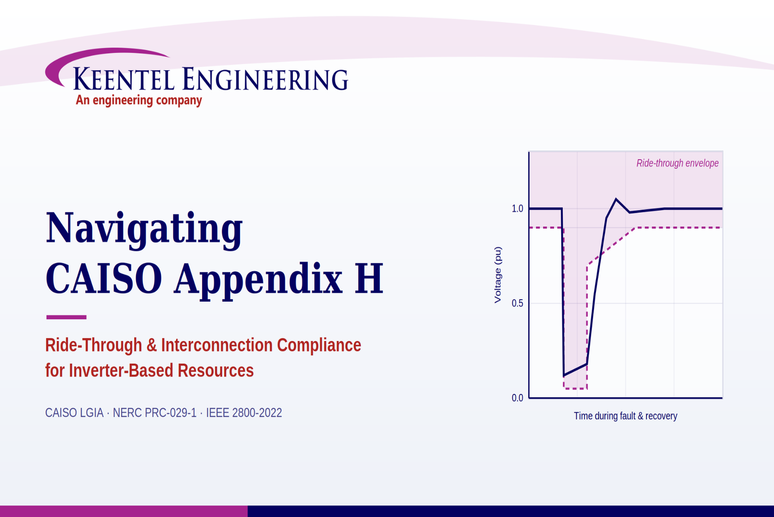
Navigating CAISO Appendix H
Jun 11, 2026 | blog
How Generator Owners can meet the technical requirements of the CAISO Large Generator Interconnection Agreement — and where the right engineering partner makes the difference.
Why Appendix H Matters Now More Than Ever
California's grid is being rebuilt around inverter-based resources (IBRs). Utility-scale solar, battery energy storage systems (BESS), and modern wind now make up a dominant and growing share of new interconnections in the CAISO footprint. With that shift comes a hard engineering reality: inverters don't behave like the synchronous machines the grid was originally designed around. Their fault-current contribution, control behavior, and ride-through performance are governed by software and power electronics, not physics and inertia.
That is precisely the gap Appendix H of the CAISO Large Generator Interconnection Agreement (LGIA) is written to close. Appendix H sets the technical interconnection requirements specific to Asynchronous Generating Facilities — the formal term for IBRs in the CAISO tariff. If you are interconnecting a solar, storage, or wind project to the CAISO Controlled Grid, the obligations in Appendix H are contractual, enforceable, and tested against real plant performance during grid disturbances.
This post walks through what Appendix H actually requires, how it interacts with the newer NERC ride-through standards, where projects commonly run into trouble, and how Keentel Engineering supports Generator Owners through each stage.
What Appendix H Covers
Appendix H applies to all Asynchronous Generating Facilities interconnecting to CAISO, with a grandfathering carve-out: existing units already interconnected at the same location are generally exempt for the remaining life of that unit (subject to a narrow exception under CAISO tariff Section 25.4.2). The requirements break into six technical areas.
1. Voltage Ride-Through Capability
This is the heart of Appendix H. The facility must remain online through voltage disturbances rather than tripping offline and worsening a grid event. Key provisions include:
- Three-phase faults: Remain online for the lesser of the normal three-phase clearing time (4–9 cycles) or 150 milliseconds, plus subsequent recovery to steady-state voltage. Clearing time is referenced to faults that drive the Point of Interconnection (POI) voltage to 0.2 per unit or below.
- Single-phase faults: Remain online through delayed (backup) clearing for single-line faults, accounting for a single point of protection or breaker failure.
- Momentary cessation: Pausing current injection during a fault is prohibited unless transient high voltage reaches 1.20 per unit or more.
- Reactive current injection: During low-voltage events, inverters must inject reactive current proportional to the voltage dip, reaching full reactive capability when terminal voltage falls to 0.50 per unit or below.
- Recovery and ramp: Once voltage returns to the normal band (0.90–1.10 per unit), inverters must transition back to real-power injection, ramping at a minimum of 100% per second, with the full transition completed in one second or less.
- Reconnection: After a trip, the inverter must make at least one resynchronization attempt within 2.5 minutes, unless a manufacturer-defined fatal fault code applies.
- Phase-lock-loop behavior: Inverters may not trip for momentary loss of synchronism; controls must hold the last synchronized phase and continue injecting current until synchronism is regained (with a 150-millisecond limit before a trip is permitted).
- Plant controllers: Plant-level controllers must not impede the inverters' automatic, rapid re-synchronization and ramp-up after a disturbance.
2. Frequency Ride-Through Capability
Appendix H defers off-nominal frequency performance to the applicable NERC Reliability Standard for generator frequency and voltage protective relay settings — "or successor requirements as they may be amended." That forward-looking language is important, because the governing NERC standards have recently changed (more on that below).
3. Power Factor / Reactive Power
Facilities must operate within a power factor range of 0.95 leading to 0.95 lagging, measured at the high side of the substation transformer, to maintain a specified voltage schedule. The precise obligation depends on whether the facility was studied under the Independent Study Process (Appendix DD, Section 4) and what the Phase II Interconnection Study determined was needed for safety and reliability. Dynamic voltage support may also be required in lieu of a power system stabilizer.
4. SCADA Capability
The facility must provide SCADA to transmit data to and receive instructions from the Participating Transmission Owner (TO) and CAISO, with the specific data set scoped to the plant's size, characteristics, location, and reliability importance.
5. Power System Stabilizers (PSS)
Not required for Asynchronous Generating Facilities.
6. Transient Data Recording
Facilities larger than 20 MW must monitor and record detailed plant- and inverter-level data for ride-through events, reactive current injection, momentary cessation, and inverter trips. The data requirements are demanding:
- Time-synchronized to 1-millisecond resolution via GPS clock.
- Sampled at least every 10 milliseconds (except phase-angle data).
- Each record captures at least 150 ms pre-trigger and 1000 ms post-trigger.
- Data stored for a minimum of 30 days and delivered within 10 calendar days of a CAISO/TO request.
- A phase angle measuring unit (≥16 samples per cycle) installed at the facility entrance or main substation transformer.
Appendix H and PRC-029-1: A Converging Landscape
A common question for California asset owners is how Appendix H relates to the NERC PRC-029-1 standard. The short answer: they share the same intent — keeping IBRs online and supportive during disturbances — but they are distinct regimes that must be reconciled, not assumed to be identical.
PRC-029-1, Frequency and Voltage Ride-through Requirements for Inverter-Based Resources, was approved by FERC in 2025 (Order No. 909) alongside PRC-024-4 for synchronous machines. It introduces performance-based, continent-wide ride-through requirements specifically tailored to IBR behavior, closing gaps left by the older PRC-024 framework. It defines ride-through zones, mandates that IBRs not cease current exchange within those zones, and requires rapid return to normal current exchange after voltage recovery.
The practical implications for a CAISO project:
Overlapping but not identical thresholds
Appendix H and PRC-029-1 both govern ride-through, but specific timing, voltage thresholds, and recovery windows differ in their details. A plant tuned only to one may not automatically satisfy the other.
Different origins and enforcement
Appendix H is a contractual interconnection provision in the LGIA; PRC-029-1 is a mandatory NERC reliability standard with its own compliance, evidence, and audit obligations (including legacy-unit exemption pathways under Requirement R4).
A moving target
Appendix H's frequency provision explicitly points to successor NERC standards, so alignment with the current NERC ride-through regime is part of staying compliant over time.
The takeaway: describe the relationship carefully in compliance documentation. Saying the Appendix H ride-through obligation is
addressed under the current NERC ride-through framework is defensible; treating the two as
equivalent is not, given the threshold and origin differences.
Where Projects Commonly Struggle
Across utility-scale solar and BESS interconnections, the same compliance pain points recur:
Inverter current limits vs. reactive injection requirements
Hardware constraints on short-duration and maximum current can make full reactive-current injection during deep voltage dips difficult to achieve.
Controller tuning trade-offs
Faster response settings risk controller instability; slower settings delay voltage recovery. Both create compliance exposure.
Plant controller interference
Plant-level controls that delay or override inverter restoration after a disturbance directly violate Appendix H.
Momentary cessation misconfiguration
Inverters configured to cease current outside the narrow permitted high-voltage band fail the standard.
Model fidelity gaps
Generic or unvalidated inverter models that don't match field behavior undermine both interconnection studies and ride-through demonstration.
Data recording shortfalls
The 20 MW recording threshold, GPS time-sync, sampling rates, and retention/turnaround obligations are frequently underbuilt.
Phase-lock-loop and loss-of-synchronism behavior.
Protection settings that trip on phase-angle shifts can conflict with the requirement to hold synchronism.
How Keentel Engineering Supports CAISO Appendix H Compliance
Keentel Engineering brings over three decades of utility-scale power system experience, with engineers licensed in California and across the U.S., and a practice built specifically around IBR interconnection and NERC/ISO compliance. Here's how that maps to the Appendix H requirements.
Dynamic and EMT Modeling
Compliance demonstration starts with credible models. Keentel develops and validates PSSE, PSCAD, TSAT, and PowerFactory models for power flow, dynamic stability, and electromagnetic transient (EMT) analysis — the foundation for proving ride-through performance to CAISO during model review and interconnection studies.
Ride-Through and Dynamic Stability Studies
Keentel performs the voltage and frequency ride-through studies that show a plant will remain online through the fault and recovery profiles Appendix H specifies — and that its behavior aligns with the current NERC ride-through framework (PRC-029-1 / PRC-024-4) as well as IEEE 2800-2022 where applicable.
Inverter and Plant Controller Tuning
To resolve the tuning trade-offs that derail compliance, Keentel optimizes inverter control parameters and plant-level control logic — including PLL tuning and coordinated low-voltage ride-through behavior — so reactive current injection, recovery ramp rates, and the one-second transition requirement are met without sacrificing stability.
Protection Coordination and Relay Integration
Keentel reviews protection philosophy, single-line diagrams, and relay logic (with deep SEL relay expertise) to ensure protection settings don't conflict with ride-through obligations or trip the plant unnecessarily during recoverable disturbances — a frequent root cause of Appendix H findings.
PRC-029-1 / PRC-024-4 Alignment and Exemptions
For owners reconciling Appendix H with the newer NERC standards, Keentel provides relay tuning and validation to align voltage and frequency trip points with PRC-024-4, prepares PRC-029-1 exemption justification packages for legacy IBRs that cannot meet current criteria, and integrates PRC-028-1 disturbance monitoring for audit readiness.
Disturbance Monitoring and Transient Data Recording
To satisfy Appendix H's transient data recording obligations, Keentel supports the design and validation of GPS-synchronized monitoring, phase angle measuring units, and the recording architecture needed to capture, retain, and deliver event data within CAISO's required windows.
Interconnection Studies and Owner's Engineer Support
From feasibility through commissioning, Keentel acts as an independent Owner's Engineer — validating EPC designs, verifying interconnection compliance, and protecting long-term asset value across CAISO and other ISO/RTO territories.
Audit Support and Documentation
Keentel guides clients through the full NERC Align workflow — pre-submittal reviews, mitigation plans, evidence packages, and Regional Entity correspondence — and delivers audit-ready documentation, validation reports, and coordination checks.
A Compliance Checklist for California Asset Owners
Before energization and before an audit confirm:
- Inverter and plant models validated against field/EMT behavior and accepted by CAISO
- Voltage ride-through performance demonstrated for both three-phase and single-phase fault profiles
- Reactive current injection proportional to voltage dip, full capability at ≤0.50 pu
- [Recovery ramp ≥100%/second, full transition ≤1 second
- [Momentary cessation limited to the permitted high-voltage band (≥1.20 pu)
- [Plant controller programmed to allow rapid, automatic inverter restoration
- Power factor capability of 0.95 leading to 0.95 lagging at the HV side, per Phase II study findings
- SCADA scope agreed with the Participating TO and CAISO
- Transient data recording in place for facilities >20 MW (GPS sync, sampling, retention, turnaround)
- Phase angle measuring unit installed and validated
- Ride-through behavior reconciled with current NERC PRC-029-1 / PRC-024-4 requirements
Technical FAQ
A reference for Generator Owners, developers, and engineers working through CAISO Large Generator Interconnection Agreement (LGIA) Appendix H requirements for inverter-based resources. Prepared with engineering support from Keentel Engineering.
1. What is an "Asynchronous Generating Facility" under Appendix H, and which projects does it apply to?
An Asynchronous Generating Facility is the CAISO tariff term for an inverter-based resource (IBR) — utility-scale solar PV, battery energy storage systems (BESS), and Type-3/Type-4 wind that connect to the grid through power electronics rather than a directly coupled synchronous machine. Appendix H sets the interconnection technical requirements specific to these facilities under the LGIA. It applies to new Asynchronous Generating Facilities interconnecting to the CAISO Controlled Grid. Existing individual generating units already (or previously) interconnected at the same location are generally exempt for the remaining life of that unit, except as provided under CAISO tariff Section 25.4.2.
2. What is the voltage ride-through requirement for a three-phase fault?
The facility must remain online through a voltage disturbance from any fault on the transmission grid — or within the facility between the Point of Interconnection (POI) and the high-voltage terminals of the step-up transformer — for a duration equal to the lesser of the normal three-phase fault clearing time (4–9 cycles) or 150 milliseconds, plus any subsequent post-fault voltage recovery to the final steady-state voltage. The one exception is if clearing the fault effectively disconnects the generator from the system. Clearing time is referenced to the maximum normal clearing time for any three-phase fault location that drives the POI voltage to 0.2 per unit or less, independent of the facility's own fault-current contribution.
3. How is the single-phase fault ride-through requirement different?
Single-phase faults must be ridden through with delayed (backup) clearing — not just normal clearing — plus post-fault recovery. The clearing time reference is the maximum backup clearing time associated with a single point of failure (a protection or breaker failure) for any single-phase fault location that reduces any phase-to-ground or phase-to-phase voltage at the POI to 0.2 per unit or less. Because backup clearing is slower than normal clearing, the single-phase ride-through window is effectively longer and more demanding than the three-phase case, reflecting the higher probability and longer duration of these events.
4. What does "remaining online" actually mean, and when is momentary cessation allowed?
Remaining online" is defined as continuous connection between the POI and the facility's units, with no mechanical isolation. Momentary cessation — ceasing to inject current during a fault without mechanically isolating — is prohibited unless transient high-voltage conditions rise to 1.20 per unit or more. In other words, inverters cannot blank out current during normal low-voltage faults; they must keep injecting. Momentary cessation is only a permitted response to severe transient overvoltage at or above 1.20 pu.
5. How much reactive current must the inverters inject during a low-voltage event?
During transient low-voltage conditions, inverters must inject reactive current that is directionally proportional to the decrease in per-unit voltage at the inverter AC terminals. The inverter must produce full reactive current capability when terminal voltage drops to 0.50 per unit or below. On the high side, the facility must continue to operate and absorb reactive current for transient voltage conditions between 1.10 and 1.20 per unit. This proportional injection/absorption behavior is what provides dynamic voltage support during disturbances.
6. What are the recovery ramp-rate and transition-time requirements after a disturbance?
Once transient conditions cease and the grid returns to the normal operating band (0.90 < V < 1.10 per unit), inverters must automatically transition back to normal active (real-power) current injection. They must ramp up at a minimum rate of 100% per second — from no output to full available output. The total transition from reactive injection/absorption back to normal active current must complete in one second or less. If momentary cessation was used during a high-voltage event above 1.20 pu, the return from that cessation must likewise be one second or less.
7. What happens after an inverter trips — is reconnection mandatory?
An inverter is considered "tripped" when its AC circuit breaker is open or it has otherwise been electrically isolated from the grid. Following a trip, the inverter must make at least one attempt to resynchronize and reconnect within 2.5 minutes of the trip. The single exception is when the trip was caused by a fatal fault code as defined by the original equipment manufacturer — in that case no reconnection attempt is required. This prevents a single recoverable trip from removing a unit from service for an extended period.
8. How does Appendix H treat loss of synchronism and phase-lock-loop (PLL) behavior?
Inverters may not trip or cease injecting current for a momentary loss of synchronism. At minimum, the controls must lock the PLL to the last synchronized point and continue injecting current at that last calculated phase until the PLL regains synchronism. Current injection during this state may be limited to protect the inverter. An inverter is only permitted to trip if the PLL is unable to regain synchronism 150 milliseconds after the loss. This provision is a frequent source of misconfiguration, because some protection schemes trip on phase-angle jumps that this clause is specifically designed to ride through.
9. What is the plant-level controller's obligation during recovery?
Inverter restoration after a disturbance must not be impeded by plant-level controllers. If the facility uses a plant controller, it must be programmed to allow the inverters to automatically re-synchronize rapidly and ramp up to active current injection without delayed ramping following transient voltage recovery — before the plant controller resumes overall coordination of the individual inverters. A plant controller that holds inverters back or imposes a slow ramp after a fault is a direct compliance failure.
10. Are there conditions under which the facility does NOT have to ride through?
Yes. Several carve-outs apply:
The facility is not required to remain online for multi-phase faults exceeding the three-phase duration in Section A.i.1, or single-phase faults exceeding the duration in Section A.i.2.
The Section A.i ride-through requirements do not apply to faults occurring between the facility's terminals and the high side of the step-up transformer.
Facilities may be tripped after the fault period if that trip is part of a special protection system (SPS/RAS).
Critically, the entire Section A.i ride-through obligation applies only if POI voltage remained within 0.90–1.10 per unit for the preceding two seconds, excluding sub-cycle transient deviations. A plant already operating outside the normal band is not held to these ride-through profiles.
11. What is the power factor (reactive power) design requirement?
Facilities must be capable of operating within a power factor range of 0.95 leading to 0.95 lagging, measured at the high-voltage side of the substation transformer, to maintain a specified voltage schedule. For a facility not studied under the Independent Study Process (Appendix DD, Section 4), this requirement applies if the Phase II Interconnection Study shows it is necessary for safety or reliability. For a facility studied under the Independent Study Process, the 0.95–0.95 capability applies as a baseline. The range can be met with power electronics, fixed and switched capacitors, or a combination (with TO and CAISO agreement). Power factor equipment may not be disabled while the facility is operating, and dynamic voltage support may be required in lieu of a power system stabilizer if the Phase II study calls for it.
12. Which frequency ride-through standard applies under Appendix H?
Appendix H does not hard-code numeric frequency thresholds. Instead, the facility must comply with the off-nominal frequency requirements in the applicable NERC Reliability Standard for Generator Frequency and Voltage Protective Relay Settings — "or successor requirements as they may be amended from time to time." This forward reference is significant: the governing NERC standard has since evolved (see Q15), so the frequency obligation is intentionally dynamic and tracks the current NERC framework.
13. What SCADA capability does Appendix H require?
The facility must provide SCADA capability to transmit data to and receive instructions from the Participating Transmission Owner (TO) and CAISO to protect system reliability. The specific data set is not fixed in the appendix; the TO, CAISO, and the Interconnection Customer jointly determine what SCADA information is essential, based on the plant's size, characteristics, location, and importance to resource adequacy and transmission reliability.
14. Are power system stabilizers (PSS) required? And what about transient data recording?
Power system stabilizers are not required for Asynchronous Generating Facilities. However, transient data recording is mandatory for facilities larger than 20 MW. Those facilities must monitor and record data for all frequency ride-through events, transient low-voltage disturbances that initiated reactive current injection, reactive injection or momentary cessation during high-voltage disturbances, and inverter trips. Required plant-level data includes three-phase voltage and current, status of reactive devices, breaker and plant-controller status, control set points, transformer tap positions, and relay trip/target data. Inverter-level data includes frequency/current/voltage during ride-through, voltage and current during cessation and reactive injection, alarm and fault codes, and DC current and voltage.
15. What are the exact data-quality, retention, and turnaround requirements for transient recording?
Time synchronization: GPS clock (or similar) to 1-millisecond resolution.
Sampling rate: at least every 10 milliseconds, except phase angle measuring unit data.
Capture window: a minimum of 150 ms of data before the triggering event and 1000 ms after the trigger.
Triggers: a frequency ride-through event, a low-voltage disturbance initiating reactive injection, momentary cessation or reactive injection for a high-voltage disturbance, or an inverter trip.
Retention: stored for a minimum of 30 days.
Delivery: all data provided within 10 calendar days of a request from CAISO or the Participating TO.
16. What is the phase angle measuring unit requirement?
The facility must install and maintain a phase angle measuring unit (or functional equivalent) at the entrance to the facility or at the main substation transformer. It must have a resolution of at least 16 samples per cycle. Like the transient recordings, this data must be stored for a minimum of 30 days and provided within 10 calendar days of a CAISO or Participating TO request. This unit provides the high-resolution phase data needed to reconstruct disturbance events and assess ride-through performance.
17. How does Appendix H relate to NERC PRC-029-1 and PRC-024-4?
They share intent — keeping IBRs online and supportive during disturbances — but are distinct regimes. PRC-029-1 (Frequency and Voltage Ride-through Requirements for Inverter-Based Resources) is a mandatory NERC reliability standard, approved by FERC in 2025, that establishes performance-based, continent-wide ride-through zones for IBRs and requires rapid return to normal current exchange after recovery. PRC-024-4 covers synchronous machines and certain wind types. Appendix H, by contrast, is a contractual CAISO interconnection provision specific to California. The thresholds, recovery windows, and enforcement mechanisms differ, so a plant tuned only to one framework may not automatically satisfy the other. In compliance documentation, it's accurate to say the Appendix H ride-through obligation is addressed under the current NERC ride-through framework — but treating the two as fully equivalent overstates the relationship.
18. How does IEEE 2800-2022 fit into all of this?
IEEE 2800-2022 is the consensus technical standard for interconnecting IBRs to the bulk power system, covering ride-through, reactive power, modeling, and protection. Major ISOs/RTOs — including CAISO — increasingly require IEEE 2800 alignment during model review and interconnection. PRC-029-1 aligns with several IEEE 2800 ride-through provisions while being structured to follow FERC Order No. 901 directives. In practice, a California IBR project often has to reconcile three overlapping references at once: the CAISO Appendix H contractual requirements, the mandatory NERC standards (PRC-029-1 / PRC-024-4), and the IEEE 2800 technical baseline. Harmonizing inverter and plant control settings across all three is a core engineering task.
19. Can a facility meet Appendix H through additional equipment rather than inverter performance alone?
Yes. Appendix H explicitly allows the facility to meet the Section A.i requirements through the performance of the generating units, by installing additional equipment within the facility, or by a combination of both. This gives owners flexibility — for example, supplemental dynamic reactive devices, STATCOMs, or other supporting equipment can be used alongside inverter capability to achieve the required ride-through and reactive performance, rather than relying solely on the inverters' native behavior.
20. Where do projects most often fail Appendix H, and how can engineering support reduce that risk?
Common failure points include: inverter current limits that prevent full reactive injection at deep voltage dips; control tuning that is either too fast (instability) or too slow (delayed recovery); plant controllers that impede inverter restoration; momentary cessation configured outside the permitted 1.20 pu band; protection settings that trip on phase-angle shifts the standard is meant to ride through; unvalidated inverter models that don't match field behavior; and under-built transient data recording. Keentel Engineering addresses these through validated PSSE/PSCAD/TSAT/PowerFactory modeling, voltage and frequency ride-through and dynamic stability studies, inverter and plant-controller (including PLL) tuning, protection coordination and relay integration review, PRC-029-1/PRC-024-4 alignment and exemption packages, disturbance-monitoring and phase-angle-unit design, and audit-ready documentation through the NERC Align workflow — supporting Generator Owners from interconnection study through commissioning and ongoing compliance.
Conclusion
Appendix H is where California's clean-energy ambitions meet grid-engineering reality. Meeting it requires more than installing compliant inverters — it takes
validated models, carefully tuned controls, coordinated protection, robust data recording, and documentation that holds up under both CAISO and NERC scrutiny. With ride-through standards converging across PRC-029-1, IEEE 2800-2022, and the CAISO tariff, the cost of getting it wrong — interconnection delays, curtailment, or compliance findings — keeps rising.

About the Author:
Sonny Patel P.E. EC
IEEE Senior Member
In 1995, Sandip (Sonny) R. Patel earned his Electrical Engineering degree from the University of Illinois, specializing in Electrical Engineering . But degrees don’t build legacies—action does. For three decades, he’s been shaping the future of engineering, not just as a licensed Professional Engineer across multiple states (Florida, California, New York, West Virginia, and Minnesota), but as a doer. A builder. A leader. Not just an engineer. A Licensed Electrical Contractor in Florida with an Unlimited EC license. Not just an executive. The founder and CEO of KEENTEL LLC—where expertise meets execution. Three decades. Multiple states. Endless impact.
Services

Let's Discuss Your Project
Let's book a call to discuss your electrical engineering project that we can help you with.
About the Author:
Sonny Patel P.E. EC
IEEE Senior Member
In 1995, Sandip (Sonny) R. Patel earned his Electrical Engineering degree from the University of Illinois, specializing in Electrical Engineering . But degrees don’t build legacies—action does. For three decades, he’s been shaping the future of engineering, not just as a licensed Professional Engineer across multiple states (Florida, California, New York, West Virginia, and Minnesota), but as a doer. A builder. A leader. Not just an engineer. A Licensed Electrical Contractor in Florida with an Unlimited EC license. Not just an executive. The founder and CEO of KEENTEL LLC—where expertise meets execution. Three decades. Multiple states. Endless impact.
Leave a Comment
Thank you for contacting us.
We will get back to you as soon as possible.
We will get back to you as soon as possible.
Oops, there was an error sending your message.
Please try again later.
Please try again later.
Related Posts
By SANDIP R PATEL
•
July 27, 2026
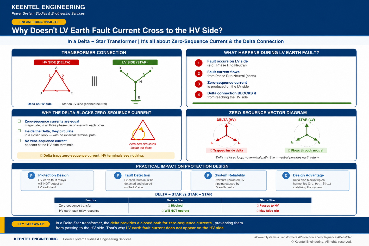
Learn why LV earth-fault current cannot cross a Delta-Star transformer, how zero-sequence current behaves, and what it means for protection design.
By SANDIP R PATEL
•
July 27, 2026
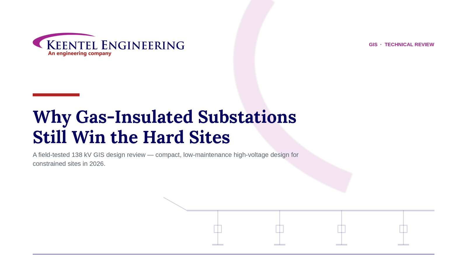
Learn how gas-insulated substations (GIS) improve safety, reliability, and space efficiency with 138 kV design, protection, insulation coordination, and real-world case studies.
By SANDIP R PATEL
•
July 25, 2026
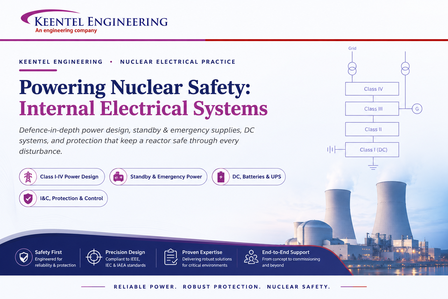
Learn how Class I–IV electrical systems, defence-in-depth, standby and emergency power, DC systems, protection, and load transfer ensure nuclear power plant safety.
By SANDIP R PATEL
•
July 24, 2026
Learn GIS substation safety best practices, SOPs, commissioning, maintenance, interlocking, earthing, and testing to improve grid reliability and uptime.
By SANDIP R PATEL
•
July 23, 2026
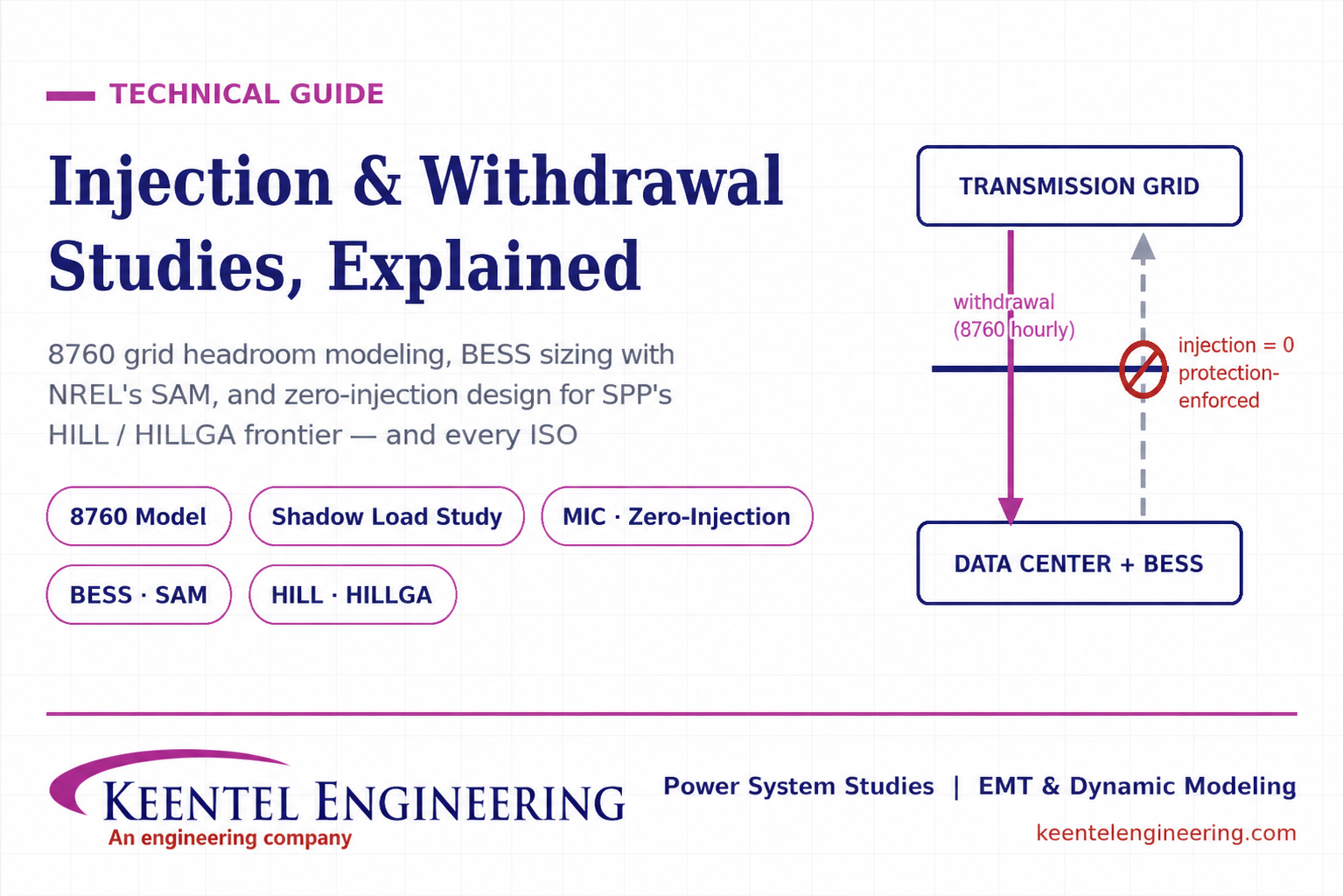
Learn how injection and withdrawal studies, 8760 headroom modeling, zero-injection engineering, and SPP HILLGA improve large load grid interconnections
By SANDIP R PATEL
•
July 21, 2026
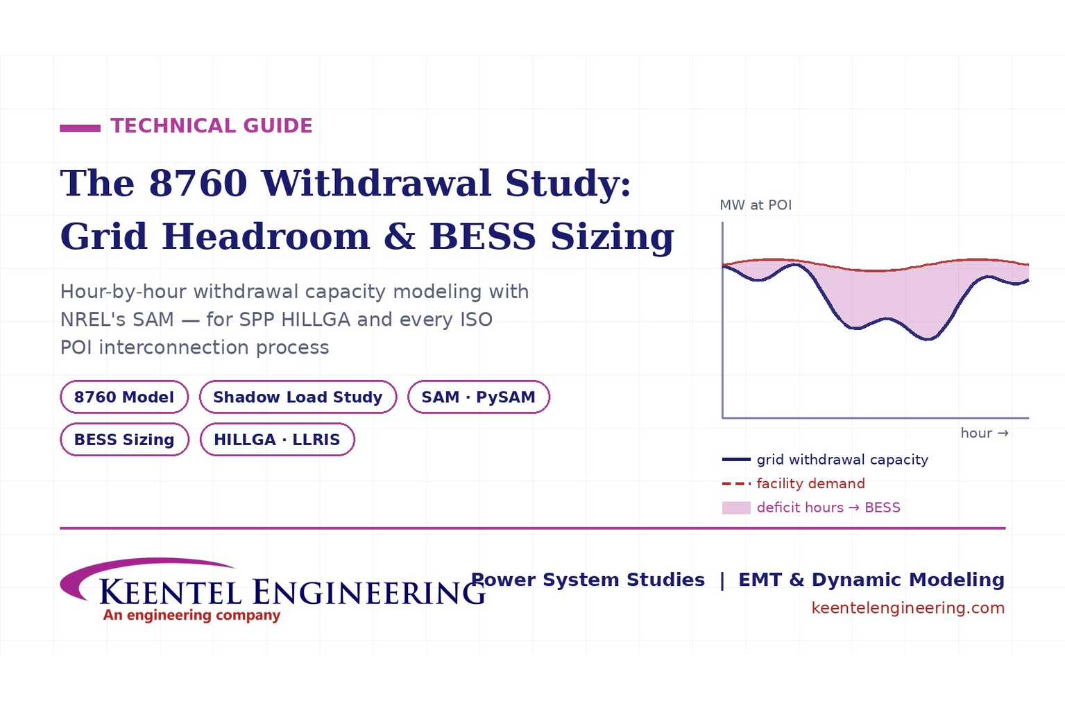
Learn how an 8760 withdrawal study models hourly grid headroom and uses SAM-based BESS sizing for large-load interconnection projects.
By SANDIP R PATEL
•
July 21, 2026
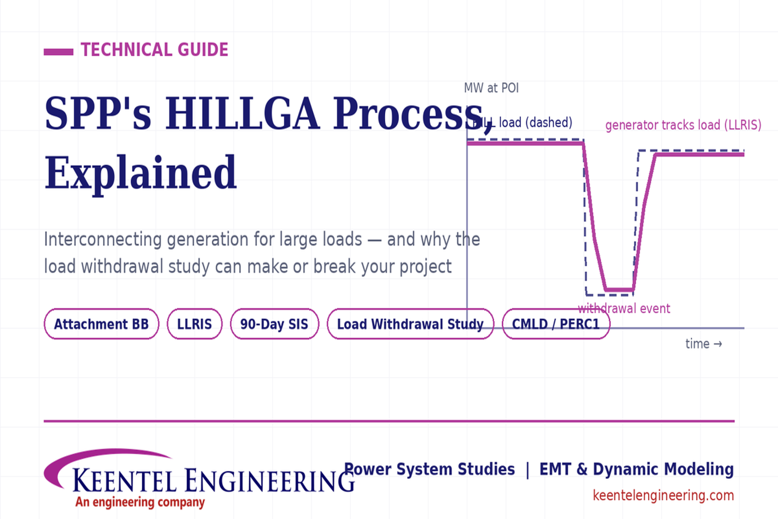
Learn how the SPP HILLGA process supports data center generation interconnection and why an 8760 withdrawal study can determine project success.
By SANDIP R PATEL
•
July 19, 2026
Learn electrical protection and relay coordination for hyperscale data centers with IEEE standards, short-circuit studies, arc-flash analysis, and MV protection.
By SANDIP R PATEL
•
July 18, 2026
Explore Battery Energy Storage System components, including cells, PCS, BMS, EMS, cooling, fire protection, sizing, safety, and grid codes.