Part A — Unbalanced Faults and IBRs at a Glance
Most transmission faults are not three-phase faults. Lightning, insulator flashovers, conductor contact with vegetation and failed equipment usually involve one phase to ground, or two phases. In utility fault statistics, single-line-to-ground (SLG) faults typically account for roughly 70% or more of transmission line faults, while bolted three-phase faults are a small minority.
Yet many interconnection studies, commissioning tests and even some plant controller designs are still built around the balanced three-phase case. For a synchronous generator that is mostly acceptable, because the machine's physics decides how it responds to unbalance. For an inverter-based resource (IBR) — solar PV, wind with a full converter, or battery storage — it is not. The inverter's response to an unbalanced fault is whatever its software was written to do, inside a hard current limit set by its semiconductors.
That raises four practical questions every IBR owner, developer and transmission owner should be able to answer:
This guide answers those questions in US terms: 60 Hz, 34.5 kV collector systems, 138 kV to 345 kV points of interconnection (POIs), IEEE Std 2800-2022, NERC PRC-029-1 and the FERC Order No. 901 program.
The plant used in this guide
Keentel Engineering uses one illustrative plant throughout so that every example connects to the others.
| Item | Value |
|---|---|
| Plant | 200 MW solar PV (the same logic applies to BESS and Type 4 wind) |
| Inverter fleet | 222 MVA total apparent-power rating; about fifty-three 4.2 MVA central inverters |
| Collector system | 34.5 kV, eight feeders, low-resistance grounded through a grounding transformer |
| Main power transformer (GSU) | 345 kV grounded-wye / 34.5 kV delta (YNd1), one 30° phase shift |
| POI | 345 kV, three-phase short-circuit strength 10,000 MVA (Z1 = Z2 = j0.01 pu on 100 MVA), X0/X1 = 1.5 |
| Inverter current limit | 1.2 pu of rated current, applied to the peak of any phase |
| Fault studied | Bolted SLG fault on phase A at the 345 kV POI bus |
What Keentel's model shows
The sequence voltages at the POI during the bolted SLG fault are V1 = 0.714 pu, V2 = 0.286 pu and V0 = 0.429 pu. Phase A collapses to zero, while phases B and C actually swell to 1.08 pu because of the zero-sequence voltage. On the 34.5 kV side of the delta winding, the zero-sequence voltage disappears and the 30° shift redistributes the sag: two phases fall to 0.62 pu and one stays at 1.00 pu. The inverter never sees "a phase A dip" — it sees a two-phase sag.
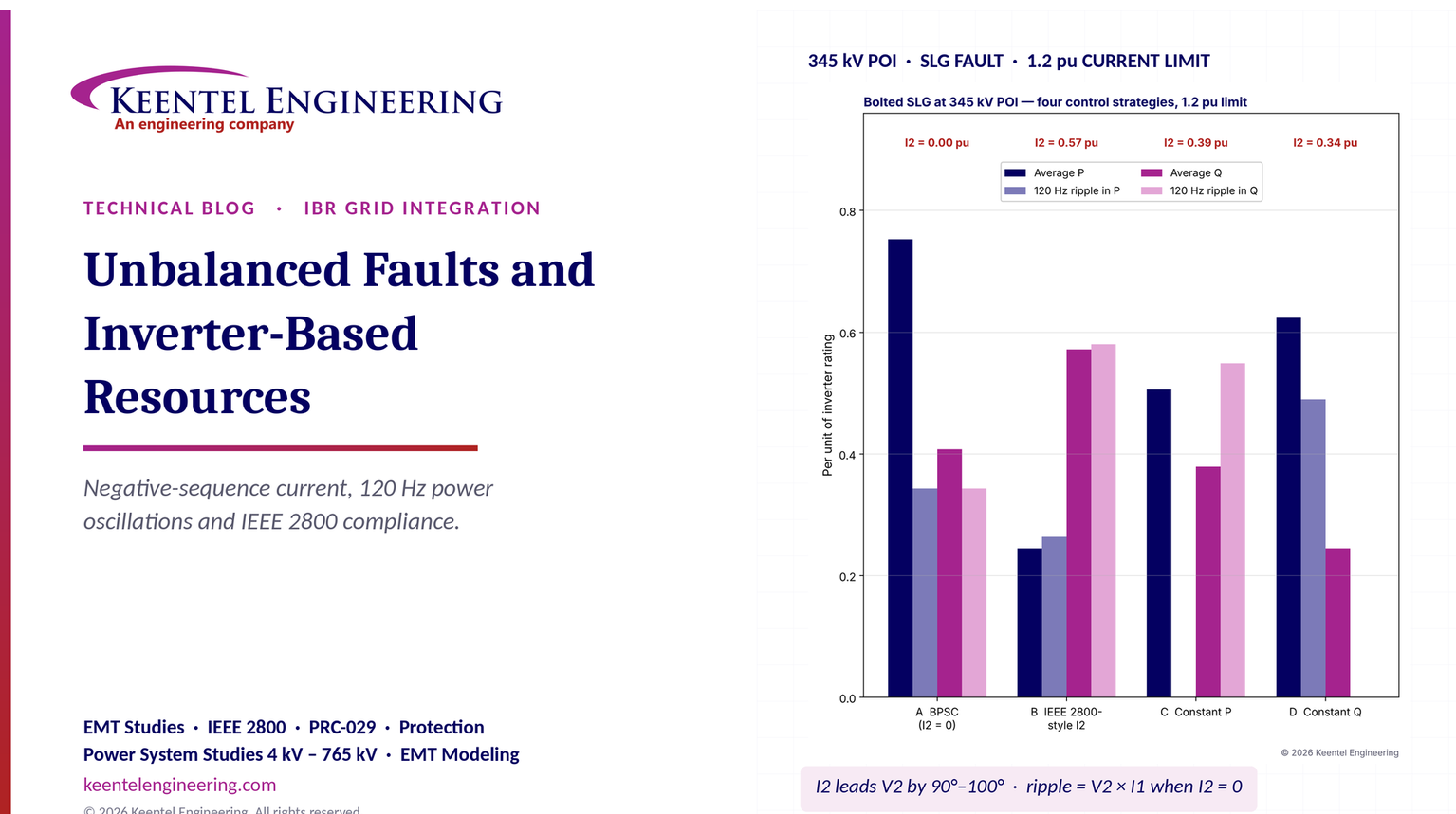
Keentel then compared four inverter current-control strategies, each limited so that the highest phase current is exactly 1.2 pu:
| Strategy | Positive-sequence current, I1 | Negative-sequence current, I2 | Average P | 120 Hz ripple in P | Average Q | 120 Hz ripple in Q |
|---|---|---|---|---|---|---|
| A. Balanced positive-sequence current (BPSC, I2 = 0) | 1.20 pu | 0 | 0.75 pu | 0.34 pu | 0.41 pu | 0.34 pu |
| B. Reactive priority plus IEEE 2800-style I2 (I2 leads V2 by 90°) | 0.67 pu | 0.57 pu | 0.25 pu | 0.26 pu | 0.57 pu | 0.58 pu |
| C. Constant active power (P ripple cancelled) | 0.96 pu | 0.39 pu | 0.51 pu | 0 | 0.38 pu | 0.55 pu |
| D. Constant reactive power (Q ripple cancelled) | 0.86 pu | 0.34 pu | 0.62 pu | 0.49 pu | 0.25 pu | 0 |
All values are on the 222 MVA inverter base. "Ripple" is the amplitude of the 120 Hz oscillation.

Five lessons
Engineering review of common statements about IBRs and unbalanced faults
| Common statement | Keentel's engineering review |
|---|---|
| "Unbalanced faults produce a 100 Hz / 120 Hz oscillation in power." | In US 60 Hz systems the oscillation is at 120 Hz only. The 100 Hz figure applies to 50 Hz systems and does not belong in US studies. |
| "Unbalanced faults introduce a negative-sequence component." | Correct, and an SLG or double-line-to-ground fault also introduces a zero-sequence component. The three-wire inverter behind a delta winding neither sees nor supplies zero sequence; the grounded-wye GSU neutral and any grounding transformer carry it. |
| A single-line diagram showing a "phase A dip at the PCC" feeding straight into the inverter. | At the POI the faulted phase dips. Behind a delta-wye GSU the inverter sees a two-phase sag (two phases near 0.62 pu, one near 1.0 pu in our example). Measurement location matters. |
| "Grid codes may require positive-sequence priority while managing or injecting negative-sequence current." | In the US this is specific. IEEE Std 2800-2022 requires full-converter IBR units to inject negative-sequence current that leads the negative-sequence voltage by 90° to 100° (90° to 150° for Type III wind), and states that the positive-sequence increment shall not be reduced below the negative-sequence increment when the current limit is reached. Magnitudes are left to the transmission owner. |
| "The interaction of positive- and negative-sequence quantities produces twice-frequency oscillation in P and Q." | Correct. The ripple amplitude can be calculated: with I2 = 0 it equals the product of V2 and I1 (0.29 × 1.2 = 0.34 pu in our example). |
| "Inverter current control adapts to the imbalance." | Only if the inverter has dual-sequence control. Many installed inverters use balanced positive-sequence control and inject essentially zero I2, which can confuse transmission protection. |
| Waveforms marked "conceptual illustration, not measured data." | Appropriate. Real responses depend on control firmware, the phase-locked loop, sequence-extraction filters and limiters, and must be confirmed with vendor-specific EMT models and field recordings. |
Part B — Technical Guide: How Inverter-Based Plants Respond to Unbalanced Faults
1. Why unbalanced faults deserve their own study
A balanced three-phase fault is the easiest case to model and the one most often shown in plant capability curves. It is also the least common. For an IBR plant, the unbalanced case is harder in four ways:
Keentel's earlier guides covered the difference between single-line-to-ground and three-phase fault currents, and how zero-sequence quantities appear in the dq0 frame. This guide builds on them and concentrates on the inverter's controlled response.
2. Symmetrical components in two minutes
Any set of three unbalanced phasors can be written as the sum of three balanced sets: positive sequence (A-B-C rotation), negative sequence (A-C-B rotation) and zero sequence (all three in phase). With the operator a = 1∠120°:

The inverse transformation rebuilds the phase quantities:

Three facts matter for IBRs:
3. Sequence networks for faults at a 345 kV POI
For a fault at a bus with Thevenin sequence impedances Z1, Z2 and Z0 and fault impedance Zf, the classic connections are:
| Fault type | Sequence network connection | Positive-sequence fault current |
|---|---|---|
| Three-phase (3φ) | Positive-sequence network only | I1 = E / (Z1 + Zf) |
| Single-line-to-ground (SLG) | Positive, negative and zero networks in series | I1 = I2 = I0 = E / (Z1 + Z2 + Z0 + 3Zf) |
| Line-to-line (LL) | Positive and negative networks in parallel-opposition | I1 = −I2 = E / (Z1 + Z2 + Zf) |
| Double-line-to-ground (LLG) | Negative and zero networks in parallel, in series with positive | I1 = E / [Z1 + Z2(Z0 + 3Zf)/(Z2 + Z0 + 3Zf)] |
The sequence voltages at the fault follow directly:

Worked example 1 — SLG fault at the 345 kV POI
Data. 100 MVA base. The 345 kV system has a three-phase short-circuit strength of 10,000 MVA, so Z1 = Z2 = j0.01 pu. The zero-sequence impedance is Z0 = j0.015 pu (X0/X1 = 1.5). The plant's own fault contribution is neglected for this first step. Bolted fault, Zf = 0.
Sequence currents.

The base current at 345 kV is 100 MVA / (√3 × 345 kV) = 167.3 A, so the fault current is 3 × 28.57 × 167.3 A ≈ 14.3 kA.
Sequence voltages.

Phase voltages. Va = 0 (the faulted phase). Vb = 1.079∠−126.6° pu and Vc = 1.079∠126.6° pu. The unfaulted phases swell by about 8% because of the zero-sequence voltage — the familiar "coefficient of grounding" effect. The line-to-line voltage between the healthy phases stays at 1.732 pu (i.e., 1.0 pu of line-to-line voltage).
With a 10 Ω fault resistance(0.0084 pu), the fault current falls to 11.6 kA, V1 rises to 0.823 pu, V2 to 0.232 pu, and the faulted phase holds 0.58 pu. Real faults are rarely bolted; studies should include a range of fault resistance.
4. Why IBRs behave differently from synchronous machines
A synchronous generator is a voltage source behind its subtransient reactance. Its negative-sequence impedance is roughly equal to X″d, so it supplies negative-sequence current in proportion to the negative-sequence voltage, with an inductive angle, automatically. Its fault current can reach five to seven times rated current for the first few cycles.
An IBR is fundamentally a controlled current source:
| Property | Synchronous generator | Grid-following inverter-based resource |
|---|---|---|
| Fault current magnitude | 5–7 pu of rated, decaying over cycles | Typically 1.0–1.5 pu of rated, held by a hard limit |
| Positive-sequence response | Set by machine reactances and excitation | Set by control: reactive current gain, priority, limits |
| Negative-sequence current | Natural, about V2 / X2, inductive | Whatever the control commands — often near zero in legacy designs |
| Zero-sequence current | Only if the GSU is grounded-wye on the machine side | None from the inverter; zero sequence comes from the GSU neutral or a grounding transformer |
| Response time | Instantaneous (physics) | Typically one to a few cycles, limited by sequence extraction and PLL |
| Frequency content | Clean fundamental with DC offset | Fundamental plus controller-dependent transients |
This is why the "equivalent source" representation that works for synchronous machines in short-circuit programs does not work for IBRs. The inverter's sequence "impedances" are really control laws.
5. What the inverter sees: the GSU and the 30° shift
Most US IBR plants step up from a 34.5 kV collector system to the transmission voltage through a grounded-wye/delta GSU (often with the delta on the 34.5 kV side and a separate grounding transformer to make the collector system effectively grounded). Under the ANSI convention, the low-voltage side lags the high-voltage side by 30° for positive sequence. For negative sequence, the shift is the opposite sign. Zero sequence does not pass through the delta at all:

Worked example 2 — the same fault seen from the 34.5 kV bus
Using V1 = 0.714 pu and V2 = −0.286 pu from Worked example 1:

Rebuilding the phase voltages without any zero-sequence term:
| Phase | 345 kV POI (phase-to-ground) | 34.5 kV bus (behind the delta) |
|---|---|---|
| A | 0.000 pu | 0.623 pu |
| B | 1.079 pu | 0.623 pu |
| C | 1.079 pu | 1.000 pu |
The single-phase collapse on the transmission side becomes a two-phase sag to 0.62 pu at the collector bus. In kilovolts, the two sagged phases are at about 21.5 kV equivalent line-to-line voltage instead of 34.5 kV. The inverter's own medium-voltage transformer (34.5 kV to roughly 0.6 kV, often delta-wye) shifts the phasors again, so the pattern at the inverter terminals may differ once more.
Worked example 2b — all four bolted fault types at the same POI
Repeating the calculation for each fault type (bolted, at the 345 kV POI, same system impedances) shows how differently they reach the collector bus:
| Fault at 345 kV POI | V1 (pu) | V2 (pu) | V0 (pu) | Phase voltages at POI (A, B, C) | Phase voltages at 34.5 kV bus (A, B, C) |
|---|---|---|---|---|---|
| Three-phase | 0.000 | 0.000 | 0.000 | 0, 0, 0 | 0, 0, 0 |
| SLG, phase A | 0.714 | 0.286 | 0.429 | 0, 1.08, 1.08 | 0.62, 0.62, 1.00 |
| LL, phases B–C | 0.500 | 0.500 | 0 | 1.00, 0.50, 0.50 | 0.87, 0.87, 0 |
| LLG, phases B–C to ground | 0.375 | 0.375 | 0.375 | 1.13, 0, 0 | 0.65, 0.65, 0 |
Two observations matter for controls. First, LL and LLG faults produce much more negative-sequence voltage (0.375–0.5 pu) than an SLG fault, so they stress negative-sequence control and the current limit hardest. Second, because the delta removes zero sequence, the collector-side pattern of an LLG fault looks like an LL fault with a deeper positive-sequence sag. Ride-through and protection studies should therefore include LL and LLG cases, not just SLG.
Practical consequence. Ride-through evaluation, inverter protection settings and event analysis must use the voltage at the correct location. A plant can ride through a POI voltage that appears to violate a curve, or trip on terminal voltages that look acceptable at the POI. PRC-029-1 measures ride-through at the high side of the main power transformer, while each inverter protects itself based on its terminal voltage — the two are not the same during unbalance.
6. Who supplies the zero-sequence current?
Because the inverter is three-wire and sits behind a delta winding, it supplies no zero-sequence current to a transmission ground fault. The zero-sequence source seen from the 345 kV system is the grounded-wye winding of the GSU (and any HV-side grounding bank). Its zero-sequence impedance is essentially the transformer's leakage reactance, and it can supply substantial ground current even when every inverter is at its current limit.
This has two effects:
The 34.5 kV collector system, by contrast, needs its own ground source (usually a zig-zag or wye-delta grounding transformer) so that collector feeder ground faults can be detected and so that healthy-phase voltages stay within arrester ratings. That subject is covered in Keentel's guide to zero-sequence quantities.
7. Dual-sequence current control
7.1 The problem with a single synchronous frame
A conventional grid-following inverter controls current in a dq reference frame synchronized to the positive-sequence voltage by a PLL. In this frame, positive-sequence quantities are DC values, which a PI controller regulates perfectly. Negative-sequence quantities rotate at −ω, so they appear in the positive frame as 120 Hz oscillations. A PI controller cannot track a 120 Hz signal, and the PLL itself oscillates.
7.2 Two frames, two controllers
Dual-sequence current control uses two reference frames: dq+ rotating at +ω and dq− rotating at −ω. Each sequence becomes a DC quantity in its own frame and is regulated by its own PI controller (or, equivalently, by a proportional-resonant controller in the stationary frame tuned to 60 Hz).
The difficulty is separating the sequences quickly. Common methods include:
| Sequence-extraction method | Principle | Typical delay | Notes |
|---|---|---|---|
| Delayed signal cancellation (DSC) | Combine the signal with a copy delayed by a quarter cycle | About 4.2 ms (one-quarter of a 16.7 ms cycle) | Simple and exact for a pure 60 Hz signal; sensitive to frequency deviation unless adaptive |
| Notch filter at 120 Hz in the dq frames | Remove the 2ω oscillation from each frame | Roughly one-half to one cycle | Slower, simple to tune |
| Dual second-order generalized integrator (DSOGI) | Generate quadrature signals adaptively, then compute sequences | About one-half to one cycle | Frequency-adaptive; widely used with an FLL |
| Decoupled double synchronous reference frame (DDSRF) | Cross-decouple the two frames mathematically | About one-half cycle | Good transient behavior |
Why this matters. The extraction delay sets a floor on how fast the inverter can respond to a fault with the correct sequence currents. Response requirements of a few cycles are achievable, but the first half-cycle to cycle of an unbalanced fault is often governed by the inverter's inner current limiter and pre-fault controls, not by the intended sequence injection. EMT models must include the vendor's actual extraction method; a generic model with ideal sequence separation will look faster and cleaner than the real plant.
7.3 The PLL during unbalance
The PLL estimates the angle of the positive-sequence voltage. During an unbalanced fault, the measured voltage contains negative sequence, which causes a 120 Hz error in the PLL's angle estimate unless the PLL uses a sequence-separated input. Weak systems make this worse, because the inverter's own current changes the voltage it is trying to track. Keentel's guide on weak-grid inverter stability treats PLL behavior in depth.
8. Instantaneous power during unbalance: where the 120 Hz comes from
When both voltage and current contain positive- and negative-sequence components, the instantaneous active and reactive power contain an average term and a term oscillating at twice the grid frequency:


The average terms come from like-sequence products (V1 with I1 and V2 with I2). The oscillating terms come from cross-sequence products (V1 with I2, and V2 with I1). Writing the dq components of each sequence in its own frame, with amplitude-invariant scaling, the six power terms depend on only four current variables:


The reactive oscillation terms Qc2 and Qs2 follow the same pattern with the signs exchanged. Exact signs depend on the transformation convention used by each vendor and tool; the structure is what matters.
The key consequence. There are six power terms (P0, Q0, Pc2, Ps2, Qc2, Qs2) but only four controllable currents (id+, iq+, id−, iq−). Once the controller fixes the average active and reactive power, only two degrees of freedom remain. It can cancel the active-power oscillation (Pc2 = Ps2 = 0) or the reactive-power oscillation (Qc2 = Qs2 = 0), but not both. This is a property of three-wire converters, not a shortcoming of any one design.
Ripple magnitude with balanced current. If the inverter injects no negative-sequence current (I2 = 0), the cross term reduces to V2 × I1, and in per unit on the inverter's own base:

In Keentel's example, 0.286 × 1.20 = 0.343 pu, which matches the time-domain result for Strategy A.
9. Control objectives during unbalanced faults
The research literature and vendor practice converge on a handful of objectives:
| Objective | What it does | Negative-sequence current | Strengths | Weaknesses |
|---|---|---|---|---|
| Balanced positive-sequence current (BPSC) | Injects balanced, sinusoidal currents | Zero | Lowest peak current for a given I1; simple; clean waveforms | P and Q both oscillate; weak support for the faulted phases; little I2 for protection |
| Positive- and negative-sequence compensation (PNSC) / constant active power | Cancels the 120 Hz active-power ripple | Set to oppose V2 × I1 interaction | Constant DC-link power; smaller DC capacitor stress | Q oscillates strongly; unbalanced currents raise peak phase current; I2 angle may not suit protection |
| Constant reactive power | Cancels the 120 Hz reactive-power ripple | Set to the other solution | Smooth reactive support | P oscillates; I2 angle can look capacitive to relays |
| Average active-reactive control (AARC) | Makes currents proportional to the voltages | Proportional to V2 | Behaves like a balanced resistive/reactive load | Neither ripple cancelled |
| IEEE 2800-style negative-sequence injection | Injects I2 leading V2 by about 90° (inductive, like a machine) | Proportional to V2, angle within a specified window | Supports protection, reduces V2 at the POI, resembles synchronous behavior | Consumes current headroom; reduces active power during the fault |
The last row is the one that matters most for US transmission-connected plants, because IEEE Std 2800-2022 adopted it.
10. IEEE Std 2800-2022 requirements for unbalanced faults
IEEE Std 2800-2022 sets minimum performance requirements for IBRs connected to US transmission and sub-transmission systems. It is not automatically mandatory; it applies when a transmission owner, independent system operator or interconnection agreement adopts it, and many have. For example, ERCOT adopted Sections 5, 7 and 9 of IEEE 2800-2022 for new transmission-connected IBRs with interconnection agreements executed on or after August 1, 2024, including negative-sequence current injection. Other transmission owners have referenced the standard in their facility interconnection requirements.
The core provisions for unbalanced faults, found in Clause 7.2.2 on current injection during ride-through, are:
A lead of 90° means the inverter behaves like an inductive negative-sequence source, which is what a synchronous machine does naturally. This angle is chosen so that transmission negative-sequence directional elements behave as they were designed to.
11. Current limiting with two sequences
The semiconductor limit applies to the instantaneous current in each phase, not to sequence magnitudes. With both sequences present, phase currents become unequal. A conservative bound is:

The exact peak depends on the angle between the sequences in each phase:

Controllers use one of three limiting schemes:
| Limiting scheme | Approach | Effect |
|---|---|---|
| Conservative sequence-sum | Limit the sum of the I1 and I2 magnitudes to the rating | Simple; leaves some phase headroom unused |
| Exact phase-peak | Compute each phase peak and scale references so the largest equals the rating | Uses the full rating; more computation |
| Priority-based | Fill reactive I1 first, then I2, then active current with the remainder (or the reverse, per requirements) | Matches IEEE 2800's priority language; active power falls first |
Worked example 3 — allocating current in the 200 MW plant
Data. The terminal-referred sequence voltages are |V1| = 0.714 pu and |V2| = 0.286 pu (Worked example 2). The plant uses a reactive-current gain of 2 for both sequences — a common starting point that the transmission owner may change:


Conservative limit. With |I1| + |I2| ≤ 1.2 pu, |I1| can be at most 1.2 − 0.572 = 0.628 pu. The remaining active current is the square root of (0.628² − 0.572²) = 0.26 pu.
Exact phase-peak limit. Scaling the active current until the most heavily loaded phase reaches exactly 1.2 pu gives |I1| = 0.667 pu and an active-current component of about 0.34 pu. The exact method recovers roughly 30% more active current than the conservative rule, because the two sequences do not add fully in any phase for these angles.
Result. Average active power falls from 0.75 pu (balanced control, no I2) to 0.25 pu (with IEEE 2800-style I2). For a 200 MW plant this is a temporary reduction of about 110 MW of injected power during the fault — acceptable for a few cycles, but it must be modeled correctly in transient-stability and frequency studies, and the energy has to go somewhere (see Section 12).
IEEE 2800 priority check. ΔIR-1 = 0.572 pu and ΔIR-2 = 0.572 pu, so ΔIR-1 is not below ΔIR-2. If the limit forced a reduction, both would be reduced equally.
Worked example 4 — 120 Hz power oscillation for four strategies
Using the same voltages and the 1.2 pu exact phase-peak limit, Keentel computed the time-domain power for each strategy over one 60 Hz cycle (table in Part A):
The exercise shows that a vendor's choice of unbalance strategy is not just an internal design detail. It changes power quality, DC-link stress and transmission protection behavior.
12. The DC link: where the 120 Hz ripple ends up
In a two-stage PV inverter or a BESS inverter, the power that enters from the DC side is nearly constant over a few milliseconds, while the power leaving on the AC side oscillates at 120 Hz. The difference charges and discharges the DC-link capacitor. Equating the energy swing:

where P̃ is the amplitude of the active-power ripple and ω = 377 rad/s.
Worked example 5 — DC-link ripple in a 4.2 MVA central inverter
Data. 4.2 MVA inverter, DC link at 1,300 V (within a 1,500 V system), DC-link capacitance 40 mF.
| Strategy | P̃ (pu) | P̃ (MW) | ΔVdc amplitude | Percent of Vdc |
|---|---|---|---|---|
| BPSC | 0.343 | 1.44 | about 37 V | 2.8% |
| IEEE 2800-style I2 | 0.264 | 1.11 | about 28 V | 2.2% |
| Constant active power | 0 | 0 | about 0 V | 0% |
These ripples are modest for a short fault, but they add to the DC voltage rise that occurs when active current is curtailed while PV or battery power continues to flow in. That rise is controlled by reducing the DC-side power (moving the PV operating point, or reducing battery discharge) or by a chopper. Plants that trip on DC overvoltage during unbalanced faults are usually suffering from the curtailment imbalance, with the 120 Hz ripple adding the final margin.
13. Transmission protection: why I2 matters
13.1 Elements that depend on negative sequence
Modern transmission line relays use negative-sequence quantities extensively:
All of these assume that the source behind the relay supplies negative-sequence current with an inductive characteristic, as a synchronous machine does. A plant that supplies no I2, or supplies it at an unusual angle, can make these elements slow, insensitive or wrong. NERC disturbance reports and IEEE Power System Relaying and Control Committee working-group reports have documented such problems at IBR-dominated line terminals.
13.2 What the relay "sees" from the plant
At the line terminal at the plant's POI, the plant is the source behind the relay. For a fault out on the line, the relay measures:

For a synchronous source, Z2,source is inductive, so the relay sees Z2 near −90° and declares a forward fault. For an inverter, Z2,source is defined by the control: if I2 leads V2 by angle θ (measured as current out of the plant), then the equivalent source impedance has angle 180° − θ.
Worked example 6 — negative-sequence directional sensitivity at the plant terminal
Data. Plant base current at 345 kV: 222 MVA / (√3 × 345 kV) = 371.5 A. CT ratio 2000:5 (400:1). PT ratio 3000:1. Typical forward negative-sequence current supervision setting: 0.5 A secondary. Negative-sequence voltage at the relay: 0.286 pu, or 57.0 kV primary phase-to-neutral.
| Strategy | Plant I2 (pu) | Primary I2 | Secondary I2 | Angle of I2 relative to V2 | Equivalent Z2 behind relay | 32Q outcome |
|---|---|---|---|---|---|---|
| BPSC | ≈ 0 | ≈ 0 A | ≈ 0 A | Undefined | Very large | Below supervision; element does not operate, or decides on stray current |
| IEEE 2800-style | 0.572 | 212 A | 0.53 A | Leads 90° | Inductive, about 268 Ω primary (35.7 Ω secondary) | Forward, but only 6% above a 0.5 A supervision setting |
| Constant active power | 0.385 | 143 A | 0.36 A | Leads about 152° | About 28° (mostly resistive) | Below a 0.5 A supervision setting; reduced angle margin if lowered |
| Constant reactive power | 0.343 | 127 A | 0.32 A | Lags about 28° | About −152° (capacitive/negative resistance) | Below supervision; if enabled, the angle reads as a reverse fault |
The lesson: even an IEEE 2800-compliant plant may produce secondary negative-sequence currents near typical relay supervision thresholds on a large CT ratio. Protection engineers should set negative-sequence supervision using the plant's actual I2 range from EMT studies, consider lower CT ratios or more sensitive settings at IBR terminals, and rely on communications-assisted schemes (permissive or blocking, with echo and weak-infeed logic) or line current differential where the IBR terminal is weak.
13.3 Distance protection
Distance elements at the IBR terminal see a source that is both weak and controlled. Ground distance elements depend on the zero-sequence current from the GSU neutral, which is usually strong, so ground distance may still work. Phase distance elements see limited and angle-shifted current, and memory-polarized mho elements can behave unpredictably because the IBR's voltage and frequency during the fault are themselves controlled. The remote terminal, with a strong system behind it, generally operates normally. A practical scheme at IBR terminals is therefore communications-assisted tripping with weak-infeed echo, or line differential, rather than step-distance alone.
14. NERC and FERC context
Several US requirements bear on unbalanced-fault performance:
15. Modeling unbalanced performance
15.1 Why positive-sequence RMS models are not enough
The generic renewable models used in planning (the REGC, REEC and REPC families) and most vendor RMS models are positive-sequence, fundamental-frequency representations. They cannot represent negative-sequence current injection, phase-current limiting under unbalance, 120 Hz power oscillations, PLL behavior with unbalanced voltage, or the exact response of protection. They remain appropriate for system-wide stability screening, but unbalanced-fault performance must be studied with electromagnetic transient (EMT) models.
15.2 What a usable EMT model must include
| Model element | Why it matters for unbalanced faults |
|---|---|
| Vendor-specific firmware representation (real-code or validated equivalent) | Generic controls do not reproduce sequence extraction, limiters or ride-through logic |
| Sequence-extraction and PLL implementation | Sets response time and behavior during the first cycles |
| Current limiter (phase-peak, sequence priority) | Determines the I1/I2 split and active power |
| Inverter protection (AC overvoltage per phase, DC overvoltage, PLL loss) | Determines whether the plant trips |
| Plant controller and its communication delays | Governs recovery after clearing |
| GSU, collector system, grounding transformer, filters and cable capacitance | Set the voltages the inverters actually see |
| Correct transformer phase shifts and winding connections | A wrong connection gives wrong terminal voltages |
15.3 Model quality tests for unbalanced performance
Keentel recommends adding these tests to the usual EMT model acceptance checklist:
15.4 Short-circuit programs
Steady-state short-circuit programs used for relay settings increasingly offer IBR representations as voltage-dependent current sources with separate positive- and negative-sequence characteristics. Keentel recommends populating these from the vendor's EMT results — for example, a table of I1 and I2 magnitude and angle versus positive- and negative-sequence voltage — rather than treating the IBR as a voltage source behind an impedance, which overstates its fault contribution.
16. Commissioning and field verification
Even a well-modeled plant needs proof that settings were applied correctly:
Part C — Three Anonymous Case Studies
These composite case studies are based on the kinds of problems Keentel Engineering sees in US IBR projects. Names, locations and identifying details have been changed or omitted.
Case study 1 — A 250 MW solar plant that tripped on healthy-phase overvoltage
Situation. A 250 MW solar plant in the Southwest, connected at 230 kV through a grounded-wye/delta GSU, lost about 60% of its output during a single-line-to-ground fault on a nearby 230 kV line. The fault cleared normally in about four cycles. The plant's output did not recover for several minutes because tripped inverters had to wait out their restart timers. The event qualified for analysis under the owner's PRC-030-1 process.
Analysis. Keentel combined the transmission owner's relay records, the plant's disturbance recorder data and inverter fault logs. Three findings stood out:
Engineered solution. Working with the inverter manufacturer, Keentel's team:
Outcome. EMT simulations showed the highest healthy-phase terminal voltage fell to about 1.07 pu, with full ride-through for all studied unbalanced faults. Two later field events confirmed it: the plant rode through with less than 5% output loss, and the PRC-028-1 recordings matched the updated model closely. The owner's PRC-030-1 corrective action plan was closed with the field evidence.
Case study 2 — A negative-sequence directional element that could not decide
Situation. A 345 kV line connected a 300 MW battery storage facility to a utility substation 18 miles away in the Midwest. During an LL fault on the line, the relay at the battery terminal did not assert its negative-sequence directional element. The permissive overreaching transfer trip scheme waited for the remote terminal's echo, and the fault cleared in about eight cycles instead of the expected three to four. No equipment was damaged, but the transmission owner flagged the slow clearing as a protection system performance issue.
Analysis. The relay event report showed a large negative-sequence voltage but only about 0.2 A secondary of negative-sequence current at the battery terminal, below the 0.5 A forward supervision setting. Keentel reviewed the battery inverters' settings and found that negative-sequence injection was available but disabled at commissioning. With balanced current control, the only negative-sequence current came from filter and cable capacitance, at an angle unrelated to the fault direction.
Engineered solution. The solution had two parts:
Outcome. Replaying the recorded fault through the updated EMT model gave about 0.9 A secondary of negative-sequence current at a 92° lead, well above the new supervision threshold and inside the forward characteristic. Relay test-set playback of the simulated currents confirmed correct directional decisions for internal and external faults. The transmission owner accepted the changes and updated its facility interconnection requirements to require negative-sequence injection settings to be submitted with relay setting data for all new IBRs.
Case study 3 — DC overvoltage trips in a wind plant during LLG faults
Situation. A 200 MW Type 4 (full-converter) wind plant in the Plains tripped about a third of its turbines during double-line-to-ground faults on the 345 kV system, while riding through SLG faults without trouble. The turbine logs showed DC-link overvoltage.
Analysis. Keentel's EMT review found that during LLG faults the positive-sequence voltage at the turbines fell further than during SLG faults, so the converters hit their current limit while the generators kept delivering power from the rotor. The DC chopper was sized for balanced faults. The converter used constant reactive power control during unbalance, which cancelled the reactive-power ripple but left a 120 Hz active-power ripple of about 0.45 pu. Combined with the steady curtailment imbalance, the peak DC voltage exceeded the trip level by about 3%.
Engineered solution. The turbine manufacturer offered a firmware update that switched to a mixed strategy: negative-sequence current led V2 by about 95° during the fault, with partial active-power ripple compensation inside the current limit. The chopper's threshold and duty were re-coordinated, and the plant controller's post-fault active-power ramp was tuned to avoid a second DC transient on recovery.
Outcome. EMT simulations of the worst LLG faults showed the DC-link peak reduced by about 8%, with margin to the trip level. The I2 angle moved into the IEEE 2800 window for full-converter units. Since the update, the plant has ridden through every recorded unbalanced fault, and the transmission owner's negative-sequence directional elements at the plant terminal have operated correctly.