A Coordinated Electric System Interconnection Review—the utility’s deep-dive on technical and cost impacts of your project.
Challenge: Frequent false tripping using conventional electromechanical relays
Solution: SEL-487E integration with multi-terminal differential protection and dynamic inrush restraint
Result: 90% reduction in false trips, saving over $250,000 in downtime
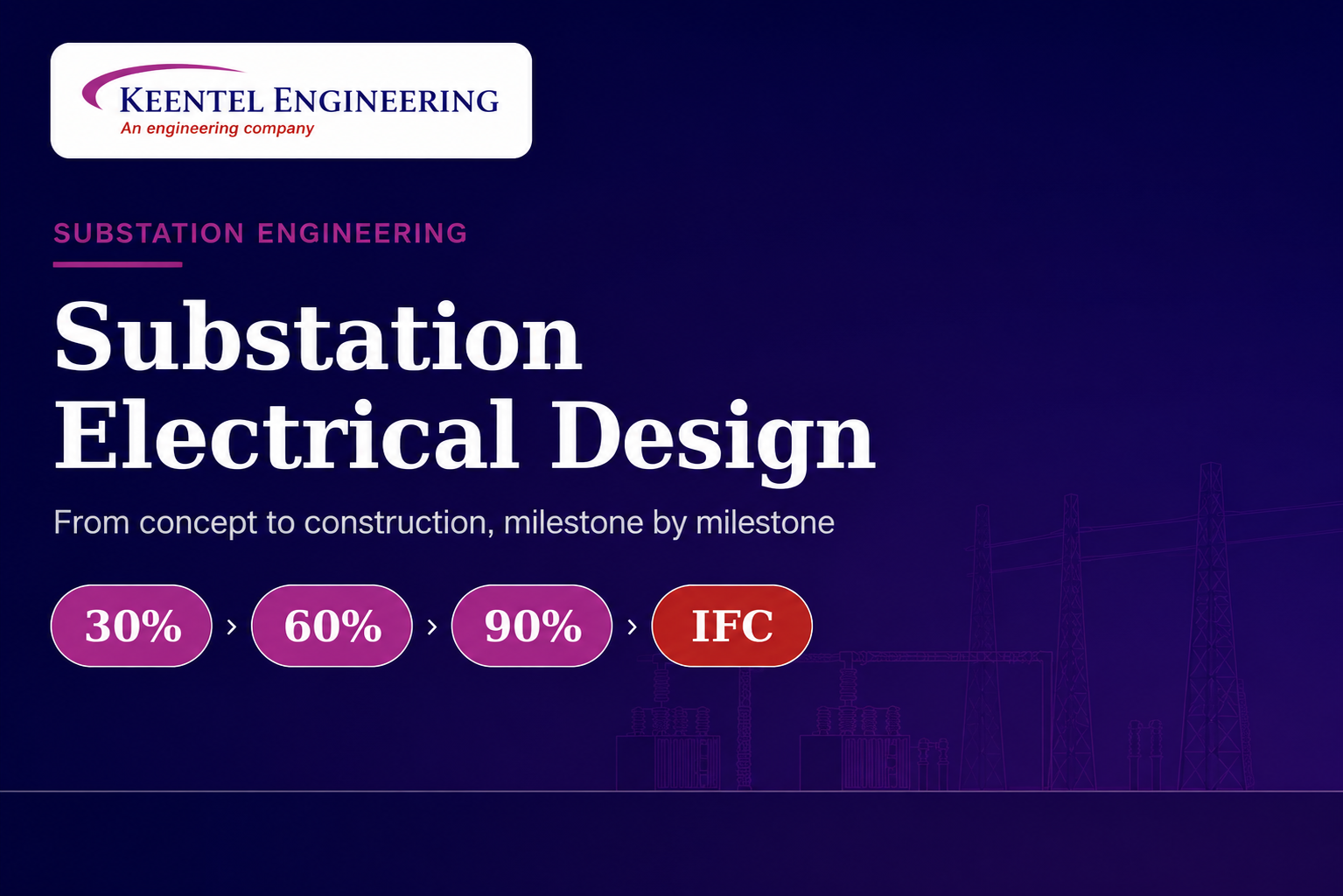
From 30% to IFC: How a Transmission Line Gets Designed
Jun 29, 2026 | Blog
Why a transmission line is designed in stages
A transmission line is not drawn once and built. It is converged on deliberately, in design gates that each retire a defined band of risk before the next dollar is committed.
Every overhead transmission line is a negotiated settlement between physics, terrain, code, cost, and schedule. The conductor wants to sag; the code wants clearance; the landowner wants the structure somewhere else; the utility wants the lowest installed cost that still survives an ice storm in fifty years. No single calculation resolves all of that at once. So the industry designs in milestones — commonly 30%, 60%, 90%, and Issued for Construction (IFC) with each gate freezing a layer of decisions so the next layer has firm ground to stand on.
The milestone framework is not bureaucracy. It is risk sequencing. Route and electrical basis are settled first because everything downstream depends on them; foundation rebar is detailed last because it depends on everything upstream. Reordering those steps is how projects generate expensive rework. This guide walks the full progression: what each gate defines, what deliverables it produces, and where the costly mistakes hide.
The one-sentence version
30% proves the line can exist on this route; 60% proves it stands up to load and clearance; 90% proves it can actually be built; IFC is the buildable, stamped, coordinated package the contractor strings steel from.
The basis of design: what's true at every gate
Before the milestones make sense, a handful of inputs govern the entire design and are established up front in the Basis of Design (BOD). These do not change milestone to milestone unless the project scope itself changes — they are the constants the gates refine against.
Electrical basis
Nominal and maximum operating voltage, continuous and emergency (e.g., summer/winter, normal/contingency) ampacity ratings, and the resulting maximum conductor operating temperature. Ampacity drives conductor selection and the thermal case that governs clearance — a line rated for 100°C operation sags far more than one rated for 75°C, and that sag is what eats clearance.
Code and loading basis
The governing edition of the National Electrical Safety Code (NESC) sets minimum vertical and horizontal clearances and the NESC district loading (heavy/medium/light) plus extreme-wind and extreme-ice cases. ASCE Manual 74 informs structural loading methodology wind pressures, ice accretion, and the load factors applied to wire tensions and structure self-weight. State and utility amendments frequently add to these minimums.
Mechanical basis
Conductor and shield-wire/OPGW type, the tension limits (initial and final, everyday and maximum), and the ruling span assumptions feed sag-tension analysis. These set how tightly the wire is strung, which trades directly against structure height, span length, and fatigue life.
| Governing input | What it controls | Typical reference |
|---|---|---|
| Operating voltage & BIL | Air clearances, insulation, phase spacing | NESC, IEEE 1313 (insulation coordination) |
| Ampacity / max temperature | Conductor size, thermal sag, clearance case | IEEE 738 (thermal rating) |
| NESC district + extreme loads | Structure & foundation loading | NESC Rule 250, ASCE 74 |
| Conductor tension limits | Sag, span length, fatigue (aeolian vibration) | Mfr. data, IEEE 1283, CIGRE |
| Clearance requirements | Structure height, span, ground profile fit | NESC Rule 232, 233, 234 |
The 30% milestone preliminary design
At 30%, the goal is to prove feasibility and fix the route and the major design choices. The deliverable set is preliminary, but the decisions it captures are the most consequential of the whole project — a wrong call here propagates through every later gate.
What gets defined
- Route selection and centerline. The corridor is chosen against constraints — wetlands, existing infrastructure, parcels, environmental and cultural resources — and a preliminary right-of-way (ROW) width is set from phase spacing and blowout.
- Survey and terrain model. LiDAR or photogrammetric survey, or at minimum existing-data terrain, is loaded into the line-design model so the ground profile is real, not assumed.
- Structure family. Steel pole vs. lattice, single vs. double circuit, tangent/angle/dead-end types, and a first cut at typical heights and a structure-type library.
- Conductor and shield/OPGW selection. Size and type chosen to meet ampacity with margin; OPGW fiber count coordinated with the communications scope.
- Preliminary sag-tension and structure spotting. A first automated spotting run places structures against the profile to test that spans, heights, and clearances are achievable.
- Major clearance check. Ground clearance, crossings (roads, rail, other lines), and edge-of-ROW clearance to the worst-case (hot, blowout) condition.
- Geotechnical and environmental kickoff. Preliminary subsurface assumptions and the permitting/environmental strategy are initiated — long-lead items that must start early.
Where 30% goes wrong
Spotting structures on an assumed flat profile instead of real survey every clearance is then fictional.
Choosing a conductor for ampacity alone and discovering at 60% that its sag forces taller, costlier structures.
Setting ROW width before blowout (wind swing) is checked, then renegotiating easements later.
30% deliverables
- Preliminary plan-and-profile (P&P) sheets with spotted structures
- Basis of Design document and design criteria
- Preliminary structure list and material quantities (for early estimating)
- Route map / alignment exhibit and ROW width basis
- Class 4/5 cost estimate input and risk register
The 60% milestone intermediate design
60% is where the line becomes structurally and electrically real. Loading is applied rigorously, structures are designed (or selected from the family) to those loads, and clearances are re-verified against the now-final wire conditions. The route is held; the engineering inside it is hardened.
What gets defined
- Finalized structure spotting. Structures are optimized against the survey — balancing span length, structure count, height, and uplift — with angle and dead-end structures placed at PIs and line ends.
- Structural loading and structure design. NESC district loads plus extreme wind and ice are applied per ASCE 74; each structure type is checked for strength against the controlling load combination, including longitudinal (broken-wire / unbalanced) cases on dead-ends.
- Final sag-tension. Initial/final, everyday and maximum-condition tensions are locked, with the governing thermal case set from ampacity and the loading cases set from NESC.
- Foundation preliminary design. Foundation type (drilled shaft, direct-embed, spread footing, pile) is selected per structure loading and the geotechnical data now in hand.
- Insulation and hardware. Insulator strings, suspension/dead-end assemblies, dampers, and spacers are specified; phase spacing and swing are confirmed for switching and lightning overvoltage.
- Grounding and shielding. Shield-wire/OPGW positioning is set for the target shielding angle; structure grounding is sized to footing-resistance targets.
- Clearance re-verification. All ground, crossing, and edge-of-ROW clearances are re-checked against the final wire positions across the full load matrix.
| Load case | Represents | Primarily sizes |
|---|---|---|
| NESC district (heavy/med/light) | Combined wind + ice + temperature with overload factors | Everyday structure & wire strength |
| Extreme wind | High-wind, no-ice event | Structure transverse strength |
| Extreme ice with wind | Radial ice + concurrent wind | Structure & foundation, conductor sag |
| Broken-wire / unbalanced | Longitudinal load from a failed span | Dead-end & angle structures, foundations |
| Maximum operating temp | Hottest conductor condition | Clearance (governing sag case) |
Where 60% goes wrong
Designing structures to district load but skipping the longitudinal broken-wire case — then dead-ends are undersized.
Locking sag-tension before the final ampacity / max-temperature case is confirmed, so clearance is checked to the wrong wire position.
Foundations sized before geotech returns, forcing redesign when actual soil parameters arrive.
60% deliverables
- Updated P&P with final spotting and clearance annotations
- Structure loading trees / loading summary per structure type
- Preliminary foundation design and reactions
- Sag-tension report and stringing condition tables
- Insulation, hardware, and grounding specifications
- Updated structure list and refined material take-off
The 90% milestone pre-final / review design
90% is the constructability and completeness gate. The design is essentially done; the work is closing gaps, finalizing details that depend on procurement and field input, and circulating the package for formal review. Few new decisions are made the focus is rigor, coordination, and catching the things that only show up when the whole set is assembled.
What gets defined
- Final foundation design. Drilled-shaft reinforcement, anchor bolts, embedment, and rebar detailing completed against final reactions and final geotechnical recommendations.
- Complete structural detailing. Final structure drawings, framing, attachment hardware, climbing/working provisions, and any guying.
- Stringing and construction sequencing. Stringing charts, sag/tension setting tables, and sagging-condition references for the field; pulling/tensioning plan inputs.
- Material take-off finalization. Full bill of materials reconciled against the structure list for procurement — conductor, OPGW, insulators, hardware, steel, foundations.
- Constructability review. Access, lay-down, crane/equipment reach, outage/clearance coordination with adjacent energized facilities, and crossing methods.
- Interdisciplinary and crossing coordination. Coordination with substation terminations, telecom (OPGW splicing/regen), road and utility crossings, and ROW/permitting closeout.
- Formal review cycle. Internal QA/QC and client/utility review comments incorporated; open items tracked to closure.
Where 90% goes wrong
Treating 90% as ‘almost IFC’ and skipping a true constructability review — access and outage problems then surface in the field.
Bill of materials drifting out of sync with the structure list, causing procurement shortfalls or surplus.
Leaving crossing permits or substation interface details ‘to be resolved,’ which become IFC-blocking items.
90% deliverables
- Near-complete drawing set: P&P, structure, foundation, grounding, hardware details
- Final foundation design package and reactions
- Stringing charts and sagging tables
- Reconciled bill of materials / final take-off
- Constructability review report and comment-resolution log
Issued for Construction (IFC)
IFC is not a further design milestone so much as the formal release of a complete, internally consistent, professionally sealed package the contractor builds from. Every comment is resolved, every drawing cross-checks against every other, and a licensed professional engineer takes responsibility by stamp and signature. Changes after IFC flow through formal revision control they are tracked, costed, and re-issued, never quietly redlined.
What an IFC package contains
- Complete, sealed drawing set plan-and-profile, structure drawings, foundation drawings, grounding, hardware and assembly details, and general notes.
- Final bill of materials and procurement-ready specifications.
- Stringing charts, sag-tension setting tables, and installation tolerances.
- Construction notes, special conditions, crossing details, and access/outage requirements.
- As-designed clearance documentation demonstrating NESC compliance across the load matrix.
- Revision block and document control established for field changes (RFIs, IFC revisions).
The IFC discipline
After IFC, design intent is fixed and field changes are managed through revision control and RFIs. The value of the milestone gates is that, by IFC, almost nothing is left to discover the line on paper and the line in the field are the same line.
Threads that run the full length of the design
Several engineering threads are not owned by any single milestone they tighten progressively at every gate. Understanding them as continuous, rather than one-time tasks, is what separates a coordinated design from a set of disconnected calculations.
Clearance
Checked preliminarily at 30%, rigorously at 60% against final wire positions, and documented at IFC. Clearance is governed by the worst-case sag — usually maximum operating temperature — not the everyday condition, which is why ampacity and sag-tension must be settled before clearance can be trusted.
Structural loading
From an NESC district assumption at 30% to a full load matrix (district, extreme wind, extreme ice, broken-wire) at 60%, to detailed foundation reactions at 90%. Loading is the spine that connects wire choices to structure choices to foundation choices.
Sag-tension
Preliminary at 30%, final at 60%, and expressed as stringing charts at 90%/IFC. Tension limits balance clearance (lower sag wants higher tension) against fatigue from aeolian vibration (high tension shortens conductor life), so they are an engineering compromise, not a maximum.
Right-of-way, environmental, and permitting
Initiated at 30% because it is long-lead, advanced through 60%/90%, and closed before IFC. Unresolved crossings or easements are among the most common causes of IFC slippage — the engineering can be finished while the line still cannot legally be built.
| Discipline | 30% | 60% | 90% / IFC |
|---|---|---|---|
| Route / ROW | Selected, width set | Held, easements advancing | Closed, permits in hand |
| Conductor / OPGW | Selected | Sag-tension final | Stringing charts issued |
| Structures | Family + prelim spotting | Designed to load matrix | Fully detailed & sealed |
| Foundations | Subsurface assumptions | Preliminary per geotech | Final reinforcement detail |
| Clearance | Major check | Full re-verification | Documented compliance |
| Estimate | Class 4/5 | Refined | Procurement-ready BOM |
The expensive mistakes and how the gates prevent them
- Designing against assumed terrain. Without survey-grade ground at 30%, every clearance and every span is a guess. The 30% gate exists to make terrain real before structures are committed.
- Selecting conductor on ampacity alone. The cheapest conductor that carries the current may sag enough to force taller structures and longer foundations. Sag economics belong in the 30%/60% conductor decision.
- Skipping load cases. District loading alone undersizes dead-ends and angle structures; the broken-wire and extreme-event cases at 60% are where those structures are actually sized.
- Detailing foundations before geotech. Foundation rebar is the last thing to fix because it depends on the most upstream uncertainty — soil. The gate order protects against costly re-design.
- Treating 90% as a formality. The constructability review is the cheapest place to find an access, outage, or crossing problem. Found in the field, the same problem is a change order.
How Keentel approaches the progression
Keentel Engineering designs transmission lines as a controlled convergence, not a single deliverable. Each gate is treated as a genuine decision point with a defined exit standard, so that risk is retired in the right order and downstream rework is minimized. Route and electrical basis are settled before structures; structures are designed to a full load matrix before foundations are detailed; and constructability is reviewed before the package is sealed.
Across milestones, Keentel maintains a single coordinated model survey, sag-tension, structure loading, and clearance live together rather than in disconnected spreadsheets so that a change in any one input propagates to every dependent check. The result at IFC is a package where the line on paper and the line in the field are the same line, and where the contractor builds from a set that has already answered the questions the field would otherwise raise.
Keentel transmission line design services
Route studies, structure spotting, and plan-and-profile development
Conductor and OPGW selection, sag-tension, and stringing charts
Structure and foundation design to NESC and ASCE 74
Clearance compliance, grounding, and insulation coordination
30% / 60% / 90% / IFC milestone packages and owner’s engineer review
contact@keentelengineering.com • 813-389-7871 • keentel.com
This article reflects general industry practice grounded in the following publicly available standards and references. Editions in force on a given project govern; the list is provided for orientation, not as project-specific design criteria.
- National Electrical Safety Code (NESC), IEEE clearances and structure/wire loading (Rules 232–235, 250)
- ASCE Manual of Practice 74 — Guidelines for Electrical Transmission Line Structural Loading
- IEEE Std 738 — Calculating the Current-Temperature Relationship of Bare Overhead Conductors
- IEEE Std 1313 — Insulation Coordination
- IEEE Std 1283 / CIGRE — conductor thermal and aeolian vibration / fatigue guidance
- Conductor and hardware manufacturer data; applicable ASTM material standards
- Applicable state and utility-specific amendments to the above
Case Studies
Three anonymized milestone narratives — 30%, 60%, and the 90%→IFC boundary.
About these case studies
The following three case studies are illustrative and fully anonymized. They contain no client names, project names, utility names, or geographic locations. Voltages, configurations, and engineering specifics are representative of standard practice and are presented to show how milestone-based design resolves real problems. Any resemblance to a specific project is coincidental.
Case Study 1 — A 30% clearance finding that changed ructuramily
A single-circuit rebuild where the most important decision of the project was made at the first gate.
Engagement at a glance
| Parameter | Detail |
|---|---|
| Scope | Rebuild and reconductor of an existing single-circuit overhead line |
| Voltage class | 138 kV |
| Driver | Increased ampacity requirement and aging structures |
| Keentel role | Line design engineer, 30% through IFC |
| Defining gate | 30% — preliminary clearance check |
Situation
An investor-owned utility client needed to increase the thermal capacity of an existing single-circuit line whose structures were near end of life. The initial direction was a like-for-like rebuild on the existing alignment, reusing the existing structure type with a larger conductor to meet the higher ampacity target. On paper, reusing the structure family promised the lowest cost and the simplest permitting, since the alignment and ROW were unchanged.
What the 30% gate revealed
When Keentel loaded survey-grade terrain into the line model and ran a preliminary sag-tension and spotting pass, the larger conductor — selected to meet the new ampacity — sagged enough at its maximum operating temperature to violate ground clearance across several spans where the original conductor had been compliant. The original structures had been sized for a smaller, lighter conductor strung at a different tension; the new thermal duty changed the governing sag case entirely.
Critically, this surfaced at 30% precisely because the check was run against real surveyed ground rather than the original design assumptions. Had the project advanced on the assumption that ‘same alignment, same structures’ was safe, the clearance shortfall would not have appeared until 60% — after structure procurement assumptions, estimates, and schedule had already been built around the wrong structure family.
The pivotal trade-off
Option A: keep the existing structure type and raise tension to reduce sag — rejected, because higher tension worsened aeolian vibration fatigue and still did not clear every span.
Option B: keep the structure type and shorten spans by adding structures — rejected on cost and ROW disturbance.
Option C: move to a taller structure family on the existing alignment — selected, because it recovered clearance across the full thermal matrix without adding structures or over-tensioning the conductor.
How it resolved through the gates
- 30%: Adopted a taller single-circuit structure family on the existing alignment; re-spotted to confirm clearance across the maximum-temperature case; updated the Basis of Design and preliminary estimate to reflect the structure change.
- 60%: Designed the new structure type to the full NESC district and extreme load matrix; finalized sag-tension at a tension that balanced clearance against fatigue; confirmed foundations were compatible with the existing ROW.
- 90%: Completed foundation detailing, stringing charts, and a constructability review covering outage coordination with the energized system during rebuild.
- IFC: Issued a sealed package with documented clearance compliance across all load cases.
Outcome
The line met its new thermal target with full clearance compliance and no ROW expansion. Because the structure-family decision was made at 30% rather than discovered at 60%, the project avoided a mid-design re-estimate and the schedule slip that a late structure change would have forced. The episode is a clean illustration of why the 30% gate exists: the cheapest place to change a structure family is before anything has been built around it.
Lesson
Reusing an existing structure family is only safe if the new conductor’s governing sag case is checked against surveyed terrain. Ampacity changes the thermal sag, and thermal sag — not the everyday condition — governs clearance.
Case Study 2 — A 60% geotechnical and loading interaction that reshaped foundations
A greenfield double-circuit line where the load matrix and the soil report had to be reconciled before foundations could be trusted.
Engagement at a glance
| Parameter | Detail |
|---|---|
| Scope | New-build greenfield double-circuit overhead line |
| Voltage class | 230 kV |
| Driver | New generation interconnection requiring firm delivery capacity |
| Keentel role | Line design engineer, with foundation coordination |
| Defining gate | 60% — loading matrix meets geotechnical reality |
Situation
A regional transmission provider was building a new double-circuit line to interconnect new generation. As a greenfield route, it carried the usual front-loaded ROW and environmental work, and the early estimate assumed a single common foundation type — a drilled shaft sized from generic soil parameters — across the line. This is a reasonable 30% assumption, but it is only an assumption until the subsurface investigation returns.
What the 60% gate revealed
Two things converged at 60%. First, the structural load matrix was applied rigorously: in addition to NESC district loading, the extreme-ice-with-wind case and the longitudinal broken-wire case on the angle and dead-end structures produced substantially higher foundation reactions than the everyday case had implied — particularly overturning moment at the larger line angles. Second, the geotechnical investigation returned variable subsurface conditions along the route, with weaker strata in part of the alignment than the generic 30% assumption.
The intersection of those two facts — higher-than-assumed reactions at angle structures, meeting weaker-than-assumed soil in some reaches — meant a single uniform foundation type would have been over-designed in good soil and under-designed in poor soil. Designing foundations before either input was firm would have produced exactly the kind of redesign the gate order is meant to prevent.
| Structure type | Governing load case | Foundation response |
|---|---|---|
| Tangent (straight runs) | Extreme wind | Standard drilled shaft, good soil reaches |
| Light angle | Extreme ice + wind | Deepened shaft where strata weaker |
| Heavy angle / dead-end | Broken-wire (longitudinal) | Enlarged shaft + reinforcement for overturning |
How it resolved through the gates
- 60%: Reconciled the full load matrix with the geotechnical report; segmented the line into foundation design reaches by soil condition; sized foundations per structure type and per reach rather than to a single uniform type.
- 90%: Completed final reinforcement detailing for each foundation reach; reconciled the bill of materials to the now-varied foundation quantities; constructability review confirmed access and drilling methods for the weaker-soil reaches.
- IFC: Sealed package with foundation schedules keyed to structure and reach, and clear field documentation of which design applied where.
Outcome
Foundations were right-sized to both load and soil — neither uniformly over-built nor locally under-built. Because the loading matrix and the geotechnical data were deliberately reconciled at 60%, before any foundation reinforcement was detailed, the project avoided detailing and then re-detailing foundations when the soil report landed. The case shows why foundation design sits late in the gate order: it depends on the two inputs (final reactions and real soil) that are themselves only firm at 60%.
Lesson
Foundations are governed by the intersection of the load matrix and the subsurface investigation. A uniform foundation assumption is fine at 30% for estimating, but foundations should not be detailed until both the broken-wire/extreme cases and the geotechnical report are in hand.
Case Study 3 — An IFC constructability resolution under live-line and crossing constraints
An uprate where the engineering was essentially settled by 90%, but the package could not be issued until construction sequencing and a major crossing were resolved.
Engagement at a glance
| Parameter | Detail |
|---|---|
| Scope | Uprate and partial relocation of an existing transmission line |
| Voltage class | 345 kV |
| Driver | Capacity uprate with a constrained construction window |
| Keentel role | Line design engineer + constructability coordination |
| Defining gate | 90% → IFC — constructability and crossing closeout |
Situation
A public power utility was uprating an existing 345 kV line, with a short relocation segment, to increase capacity. By 90% the line engineering was sound: structures were designed to the full load matrix, sag-tension and clearances were verified, and foundations were detailed. The remaining risk was not analytical — it was whether the line could actually be built within the available outage window while adjacent circuits stayed energized, and how to execute a crossing of a major existing facility along the route.
What the 90% constructability review revealed
The constructability review — the formal purpose of the 90% gate — surfaced three issues that, while not changing the design intent, would have blocked or endangered construction if they had reached the field unresolved:
- Outage sequencing. The available outage window was too short to rebuild the full segment in one pass while keeping the parallel circuit energized; the stringing sequence had to be staged so that clearances to the energized circuit were maintained at every step, not just in the final condition.
- Crossing execution. The line crossed a major existing facility, requiring a specific guard-structure and stringing method to protect the facility during conductor pulling — a means-and-methods detail that had to be reflected in the construction notes.
- Access and lay-down. Part of the relocation segment had constrained equipment access, limiting crane reach and dictating which structures could be set by which method — affecting the construction sequence and schedule.
Why this belonged at the 90% → IFC boundary
None of these issues changed a calculated quantity. All three changed how and in what order the line gets built. The constructability review is the cheapest place to find them; the same issues found in the field during a live outage are safety events and change orders.
How it resolved into IFC
- Staged the stringing and structure-setting sequence so that clearance to the energized parallel circuit was maintained at every intermediate construction state, and documented that sequence in the construction notes.
- Specified the crossing guard structure and stringing method and added it to the IFC drawings and notes, with the temporary clearances called out explicitly.
- Annotated access and equipment-method constraints by structure so the contractor’s plan aligned with the as-designed assumptions.
- Closed the open items through the formal review-comment log before sealing, so the IFC set carried no ‘to be resolved’ notes.
Outcome
The IFC package was issued as a genuinely buildable set: the contractor received not only the line design but the sequence, crossing method, and access constraints that made it constructible within the outage window and safe alongside energized circuits. Because the constructability review was treated as a real gate rather than a formality, the issues were resolved on paper at the lowest possible cost — rather than discovered during a live-line outage, where they would have been the most expensive and the most dangerous.
Lesson
By 90%, analytical design can be complete while the project is still not buildable. The constructability review exists to convert a correct design into a build sequence — outage staging, crossings, access — so that IFC is not just ‘done’ but executable.
What the three cases share
Each case turned on a different gate 30%, 60%, and the 90%→IFC boundary — but all three illustrate the same underlying principle: the milestone framework retires risk in the order the design actually depends on it. The decisive issue in each project was caught at the gate designed to catch it, and therefore resolved on paper rather than in the field.
| Case | Decisive gate | What it caught | Why the gate mattered |
|---|---|---|---|
| 1 — 138 kV rebuild | 30% | New conductor sag violated clearance | Structure family changed before anything was built around it |
| 2 — 230 kV greenfield | 60% | Load matrix met variable soil | Foundations right-sized before detailing began |
| 3 — 345 kV uprate | 90% → IFC | Outage staging, crossing, access | Design made buildable before a live outage |
How Keentel applies this
Keentel treats every gate as a real decision point with a defined exit standard, working from a single coordinated model so survey, sag-tension, loading, and clearance stay consistent. The aim is simple: by IFC, the line on paper and the line in the field are the same line.
Transmission line design 30% through IFC, plus owner’s engineer review.
contact@keentelengineering.com • 813-389-7871 • keentel.com
Notice
This document is published by Keentel Engineering for general professional information. It reflects standard industry engineering practice and Keentel's own methodology; it is not project-specific design guidance and does not establish an engineer-client relationship.
All case studies are illustrative and fully anonymized: no client names, project names, or locations are disclosed. Any resemblance to a specific project is coincidental.
Standards, codes, and organizations referenced (e.g., NESC, ASCE, IEEE, IEC, ASTM, OSHA) are the property of their respective owners. Keentel Engineering is independent and not affiliated with, endorsed by, or sponsored by any such organization.
Design FAQ
Plain answers to the questions clients ask
about
milestone-based line design.
The milestone framework
Why is transmission line design split into 30%, 60%, 90%, and IFC?
Because the design depends on itself in a fixed order. Route and electrical basis govern everything downstream; foundation rebar depends on everything upstream. Designing in gates lets each stage freeze a layer of decisions so the next layer has firm ground. It is risk sequencing, not paperwork — each gate retires a defined band of uncertainty before more money is committed.
What does each percentage actually mean?
The percentages are a convention for design completeness, not a precise measure. In practice: 30% proves the line can exist on the chosen route and fixes the major choices; 60% proves it survives its loads and holds every clearance; 90% proves it can be built, procured, and constructed; and IFC (Issued for Construction) is the complete, coordinated, professionally sealed package the contractor builds from.
Are these the only milestones?
No. Utilities and projects use variations — some add a 10% or conceptual gate, a 100% pre-IFC review, or a separate ‘Issued for Review’ stage. Some merge 90% and IFC. The principle is constant regardless of the labels: settle the most consequential, hardest-to-reverse decisions first, and leave the most detail-dependent work for last.
Inputs and standards
What has to be known before design even starts?
The Basis of Design: operating voltage and insulation level, continuous and emergency ampacity (which sets the maximum conductor temperature), the governing NESC edition and loading district, extreme wind and ice cases, conductor and shield-wire/OPGW type, and tension limits. These are the constants the milestones refine against.
Which codes and standards govern the design?
The National Electrical Safety Code (NESC) governs clearances and the basic loading framework. ASCE Manual 74 informs structural loading methodology. IEEE 738 governs the conductor thermal rating that sets sag; IEEE 1313 covers insulation coordination; manufacturer and CIGRE/IEEE guidance covers conductor fatigue. State and utility amendments frequently add to these minimums, and the edition in force on the project always governs.
What is the difference between NESC district loading and extreme loading?
NESC district loading (heavy, medium, or light, by geographic district) is a combined wind-plus-ice-plus-temperature case with overload factors that sizes everyday strength. Extreme wind (high wind, no ice) and extreme ice with concurrent wind are separate, more severe events that often control the structure and foundation design. A complete design checks all of them, plus longitudinal broken-wire cases.
Conductors, sag, and clearance
How is the conductor selected?
It must carry the required current within its temperature limit (ampacity), but that is only the start. The conductor that meets ampacity most cheaply may sag enough to force taller structures and larger foundations, so the real selection balances electrical capacity against sag economics, strength, and fatigue performance. This is why conductor choice is made early, at 30%/60%, when it can still shape the structures.
Why does clearance depend on temperature?
A conductor expands and sags more as it heats. The lowest point of the line, and therefore the clearance to the ground or a crossing, is worst at the maximum operating temperature — not at the everyday condition. That is why ampacity and sag-tension must be settled before clearance can be trusted, and why clearance is verified against the full load and temperature matrix at 60%.
What is sag-tension analysis and why does it matter so much?
It is the calculation of how much the conductor sags and how much tension it carries across every relevant condition — initial and final, everyday and extreme, cold and hot. Sag drives clearance and structure height; tension drives structure loading and conductor fatigue life. Higher tension reduces sag but shortens conductor life through aeolian vibration, so the tension limits are an engineering compromise, not a maximum.
What is OPGW and when is it decided?
Optical Ground Wire is a shield wire with optical fibers inside, providing both lightning shielding and a communications path. Its position is set by the target shielding angle, and its fiber count is coordinated with the telecom scope. It is selected at 30%, positioned at 60%, and its splicing and regeneration details are coordinated by 90%/IFC.
Structures and foundations
What does each milestone deliver?
Broadly: 30% delivers preliminary plan-and-profile, the Basis of Design, a preliminary structure list, and an early estimate. 60% delivers final spotting, structure loading and design, final sag-tension, and preliminary foundations. 90% delivers a near-complete sealed-ready drawing set, final foundations, stringing charts, a reconciled bill of materials, and a constructability review. IFC delivers the complete, sealed, coordinated construction package.
Why are foundations designed last?
Foundation design depends on the most upstream uncertainty: the soil. It needs both the final structure reactions (from 60% structural design) and the geotechnical recommendations from the subsurface investigation. Detailing foundation reinforcement before geotech returns is a common cause of expensive redesign, so the gate order deliberately puts it near the end.
What is structure spotting?
Placing each structure along the surveyed ground profile so that spans, structure heights, and clearances all work together while minimizing total cost. It balances longer spans (fewer, taller structures) against shorter spans (more, shorter structures), and places angle and dead-end structures where the line turns or terminates. Preliminary at 30%, optimized and finalized at 60%.
What does each milestone deliver?
Broadly: 30% delivers preliminary plan-and-profile, the Basis of Design, a preliminary structure list, and an early estimate. 60% delivers final spotting, structure loading and design, final sag-tension, and preliminary foundations. 90% delivers a near-complete sealed-ready drawing set, final foundations, stringing charts, a reconciled bill of materials, and a constructability review. IFC delivers the complete, sealed, coordinated construction package.
Gate
Core question
Headline deliverable
30%
Can the line exist here?
Preliminary P&P + Basis of Design
60%
Does it survive loads & clearance?
Structure design + final sag-tension
90%
Can it be built?
Constructability review + final foundations
IFC
All questions closed
Sealed construction package
Schedule, deliverables, and risk
When are structures actually designed?
A structure family (type, material, typical heights) is chosen at 30% and preliminarily spotted against the terrain. Full structural design — checking each type against the controlling load combination, including longitudinal broken-wire cases on dead-ends and angles — happens at 60%. Final detailing is completed at 90% and sealed at IFC.
What are the most common causes of rework?
Designing against assumed rather than surveyed terrain; selecting a conductor on ampacity alone and discovering its sag problem later; skipping load cases so dead-ends are undersized; detailing foundations before geotech; and treating 90% as a formality and skipping a real constructability review. The milestone gates exist specifically to catch each of these before it becomes a field change.
Can the design change after IFC?
Yes, but through formal revision control — RFIs and re-issued IFC revisions — never quiet redlines. Changes after IFC are tracked, costed, and re-coordinated across the whole set. The point of the milestone discipline is that, by IFC, very little is left to discover, so post-IFC changes are the exception rather than the rule.
What is an owner’s engineer, and how does it relate to these milestones?
An owner’s engineer (OE) represents the project owner’s interests — reviewing each milestone deliverable for completeness, code compliance, and constructability, and confirming that each gate truly meets its exit standard before the project advances. The milestone structure gives the OE natural, defined review points rather than a single end-of-project check.
Working with Keentel
How does Keentel run the milestone progression?
Keentel treats each gate as a real decision point with a defined exit standard, maintaining a single coordinated model — survey, sag-tension, structure loading, and clearance together — so a change in any input propagates to every dependent check. Route and electrical basis are settled before structures; structures are designed to a full load matrix before foundations are detailed; and constructability is reviewed before the package is sealed.
What transmission line services does Keentel provide?
Route studies and structure spotting; plan-and-profile development; conductor and OPGW selection, sag-tension, and stringing charts; structure and foundation design to NESC and ASCE 74; clearance compliance, grounding, and insulation coordination; 30%/60%/90%/IFC milestone packages; and owner’s engineer review. Keentel can be reached at contact@keentelengineering.com or 813-389-7871.

About the Author:
Sonny Patel P.E. EC
IEEE Senior Member
In 1995, Sandip (Sonny) R. Patel earned his Electrical Engineering degree from the University of Illinois, specializing in Electrical Engineering . But degrees don’t build legacies—action does. For three decades, he’s been shaping the future of engineering, not just as a licensed Professional Engineer across multiple states (Florida, California, New York, West Virginia, and Minnesota), but as a doer. A builder. A leader. Not just an engineer. A Licensed Electrical Contractor in Florida with an Unlimited EC license. Not just an executive. The founder and CEO of KEENTEL LLC—where expertise meets execution. Three decades. Multiple states. Endless impact.
Services

Let's Discuss Your Project
Let's book a call to discuss your electrical engineering project that we can help you with.
About the Author:
Sonny Patel P.E. EC
IEEE Senior Member
In 1995, Sandip (Sonny) R. Patel earned his Electrical Engineering degree from the University of Illinois, specializing in Electrical Engineering . But degrees don’t build legacies—action does. For three decades, he’s been shaping the future of engineering, not just as a licensed Professional Engineer across multiple states (Florida, California, New York, West Virginia, and Minnesota), but as a doer. A builder. A leader. Not just an engineer. A Licensed Electrical Contractor in Florida with an Unlimited EC license. Not just an executive. The founder and CEO of KEENTEL LLC—where expertise meets execution. Three decades. Multiple states. Endless impact.
Leave a Comment
We will get back to you as soon as possible.
Please try again later.
Related Posts