
A Coordinated Electric System Interconnection Review—the utility’s deep-dive on technical and cost impacts of your project.
Challenge: Frequent false tripping using conventional electromechanical relays
Solution: SEL-487E integration with multi-terminal differential protection and dynamic inrush restraint
Result: 90% reduction in false trips, saving over $250,000 in downtime
ERCOT enforces all of the above through simulation, which means your model is your compliance case. The bar is now high:
- Whole-facility scope. The model must represent everything the IT load, the UPS and power conversion, the cooling plant, the protection and control systems in formats compatible with ERCOT's study platforms (PSS/E, PSCAD, TSAT).
- Real control loops, not approximations. Generic textbook representations are unacceptable. The model must capture the actual inner control behavior of your power electronics.
- Hardware-validated converter models. For electronic loads, the PSCAD model must be benchmarked against actual hardware testing including voltage ride-through and subsynchronous response. A model assembled from standard PSCAD library blocks fails by definition, because a generic block has never been tested against your vendor's hardware. The good news: validation is a hardware-type test, so results for a given converter product are reusable across every facility that uses it.
- Format migration. Facilities that previously submitted the older composite load model (CMLD) format must transition to EPRI's PERC1 format.
- Three checkpoints. Models are reviewed before the stability study begins (no model, no study), before each quarterly stability assessment, and for electronic loads one final time before energization, when you must submit as-built models with a documented comparison against the previously studied data and a sworn attestation that the model matches actual field settings. ERCOT's review takes 10 business days, extendable by 20 put it on your critical path.
- A living obligation. Change your technology, controls, or relay settings in a way that affects ride-through including converting a crypto mining site to an AI data center — and you've triggered a new interconnection study, even if your megawatts don't change.
| Parameter | Detail |
|---|---|
| System | 230 kV / 138 kV transmission corridors, wind and wet-snow icing exposure |
| Data basis | 15 years of minute-resolution forced-outage records + regional weather observations |
| Core methods | Event grouping, MVA performance curves, time-to-95%-restore, area outage rate curves, fragility modeling, rerun-history benefits, exceedance and log-domain risk metrics |
| Headline result | ≈85% of maximum resilience benefit at 60% of original capital; worst-event restoration window cut from 11 days to 5 in rerun-history terms |
| Decision supported | Capital portfolio selection; resilience plan filing; post-investment verification framework |
| System / Topic | Governing Standard(s) | What It Controls |
|---|---|---|
| Overall plant electrical distribution | IEEE 141 (Red Book); IEEE 666 | Distribution architecture, voltage selection, design of generating station auxiliary service systems |
| Power system studies | IEEE 399 (Brown Book); IEEE 551 | Load flow, symmetrical/asymmetrical short circuit, motor starting methodologies down to the lowest LV panelboard |
| Protection & coordination | IEEE 242 (Buff Book); IEEE 3004.5; IEEE C37 series | Generator relaying (21, 59N, 87G), time-current coordination, selective clearing between LV and MV tiers |
| GSU / UAT / SST transformers | IEEE C57.12.00 and C57 family | Transformer ratings, impedance, testing, loading |
| HV switchyard breakers | IEEE C37.06 | AC high-voltage circuit breaker preferred ratings |
| MV switchgear (13.8 kV) | IEEE C37.20.2; IEEE C37.20.7 | Metal-clad construction, compartmentalization, vacuum breakers; arc-resistant design with plenum venting |
| MV cable | UL 1072; ICEA S-93-639 (NEMA WC 74) | Type MV-105 shielded cable, 133% insulation level for HRG systems |
| LV switchgear (480 V) | IEEE C37.13; UL 1558 | Metal-enclosed LV power circuit breaker switchgear to 635 V, draw-out ACBs with electronic trip units |
| Motor control centers | UL 845; NEMA ICS 18 | LV-MCC construction, MCCB/MCP protection for motors under ~200 HP |
| Motors | NEMA MG-1 | Motor performance, starting characteristics, service factors |
| DC & battery systems | IEEE 485; IEEE 946 | Lead-acid battery sizing (125/250 VDC), DC auxiliary system design |
| Grounding | IEEE 80; IEEE 142 (Green Book) | Ground grid step/touch potential limits; system grounding including high-resistance grounding |
| Lightning protection | IEEE 998 | Direct-stroke shielding of switchyard and outdoor generator structures |
| Arc flash & electrical safety | IEEE 1584; NFPA 70E | Incident energy calculation; worker safety boundaries and PPE |
| Fire protection | NFPA 850 | Fire protection and risk management for combustion turbine generating plants |
| Installation code | NEC (NFPA 70); NESC | Wiring methods inside the plant fence; overhead/outdoor clearances at the switchyard |
| Interconnection & compliance | FERC LGIP; NERC MOD-025/026/027, PRC-019/024/029, FAC-008 | Interconnection process, model validation, protection/ride-through coordination, facility ratings |
| IFC / Construction Deliverable | Purpose |
|---|---|
| Stamped IFC packages | Legal basis for construction; P.E. responsible charge |
| Final relay settings & TCCs | Protection as-installed matches the coordination study |
| Calculation archive | Owner records; NERC audit evidence trail |
| Commissioning procedures | Safe, sequenced energization; MOD field testing |
| Construction support | RFIs, field changes, FAT/SAT witness |
| As-builts & model handoff | Operating baseline; future study currency |
| Metric | Outcome |
|---|---|
| Defects found pre-occupancy | Three topology defects and one settings-mismatch family corrected before load migration; the shared-switchboard defect alone would have invalidated the concurrently-maintainable claim on day one |
| IST findings | Fourteen additional discrepancies surfaced under scenario testing (control logic, alarm mapping, one generator sequencing fault) — all closed before handover instead of during operations |
| Black-building test | Passed on second execution; the first attempt exposed the generator sequencing fault under true block load, exactly the failure the compressed plan would never have found |
| Handover quality | Operations team certified on the actual failure scenarios; corrected EOPs and settings documentation delivered as controlled documents |
| Business outcome | Occupancy proceeded three weeks behind the original date — against an independent estimate that the uncorrected sequencing fault carried a high probability of a full facility outage within the first year |
Part 2 — Frequently Asked Questions: Large Load Interconnection
| Contact | Details |
|---|---|
| Headquarters | 400 N Ashley Dr STE 2600, Tampa, FL 33602 |
| Phone | (813) 389-7871 |
| contact@keentelengineering.com | |
| Florida Firm Registration | No. 36853 |
| Additional Offices | Austin, TX • Sacramento, CA • Baltimore, MD |
| Who | Acronym | Plain-English Role |
|---|---|---|
| ERCOT | — | The grid's air traffic controller. It doesn't own power lines or plants; it directs the flow of electricity across most of Texas and referees the admission process for new generators. |
| Interconnecting Entity | IE | You — the developer or owner trying to connect a new plant (or significantly modify an existing one). You file the application and drive the process. |
| Resource Entity | RE | The registered owner/operator of the generator once it becomes an official market participant. Often the same company as the IE, wearing a different hat. |
| Qualified Scheduling Entity | QSE | Your plant's voice on the grid. The QSE handles round-the-clock communications with ERCOT — telemetry, schedules, dispatch instructions. Every generator must have one. |
| Transmission Service Provider | TSP | The utility that owns the wires and substation you'll connect to. The TSP runs your detailed study, builds the connection facilities, and signs your interconnection contract. |
| RIOO-IS | — | ERCOT's online portal where the whole process lives — applications, documents, status tracking, and checklists all flow through it. |
| Who | Acronym | Plain-English Role |
|---|---|---|
| ERCOT | — | The grid's air traffic controller. It doesn't own power lines or plants; it directs the flow of electricity across most of Texas and referees the admission process for new generators. |
| Interconnecting Entity | IE | You — the developer or owner trying to connect a new plant (or significantly modify an existing one). You file the application and drive the process. |
| Resource Entity | RE | The registered owner/operator of the generator once it becomes an official market participant. Often the same company as the IE, wearing a different hat. |
| Qualified Scheduling Entity | QSE | Your plant's voice on the grid. The QSE handles round-the-clock communications with ERCOT — telemetry, schedules, dispatch instructions. Every generator must have one. |
| Transmission Service Provider | TSP | The utility that owns the wires and substation you'll connect to. The TSP runs your detailed study, builds the connection facilities, and signs your interconnection contract. |
| RIOO-IS | — | ERCOT's online portal where the whole process lives — applications, documents, status tracking, and checklists all flow through it. |
| Who | Acronym | Plain-English Role |
|---|---|---|
| ERCOT | — | The grid's air traffic controller. It doesn't own power lines or plants; it directs the flow of electricity across most of Texas and referees the admission process for new generators. |
| Interconnecting Entity | IE | You — the developer or owner trying to connect a new plant (or significantly modify an existing one). You file the application and drive the process. |
| Resource Entity | RE | The registered owner/operator of the generator once it becomes an official market participant. Often the same company as the IE, wearing a different hat. |
| Qualified Scheduling Entity | QSE | Your plant's voice on the grid. The QSE handles round-the-clock communications with ERCOT — telemetry, schedules, dispatch instructions. Every generator must have one. |
| Transmission Service Provider | TSP | The utility that owns the wires and substation you'll connect to. The TSP runs your detailed study, builds the connection facilities, and signs your interconnection contract. |
| RIOO-IS | — | ERCOT's online portal where the whole process lives — applications, documents, status tracking, and checklists all flow through it. |
| Who | Acronym | Plain-English Role |
|---|---|---|
| ERCOT | — | The grid's air traffic controller. It doesn't own power lines or plants; it directs the flow of electricity across most of Texas and referees the admission process for new generators. |
| Interconnecting Entity | IE | You — the developer or owner trying to connect a new plant (or significantly modify an existing one). You file the application and drive the process. |
| Resource Entity | RE | The registered owner/operator of the generator once it becomes an official market participant. Often the same company as the IE, wearing a different hat. |
| Qualified Scheduling Entity | QSE | Your plant's voice on the grid. The QSE handles round-the-clock communications with ERCOT — telemetry, schedules, dispatch instructions. Every generator must have one. |
| Transmission Service Provider | TSP | The utility that owns the wires and substation you'll connect to. The TSP runs your detailed study, builds the connection facilities, and signs your interconnection contract. |
| RIOO-IS | — | ERCOT's online portal where the whole process lives — applications, documents, status tracking, and checklists all flow through it. |
| Who | Acronym | Plain-English Role |
|---|---|---|
| ERCOT | — | The grid's air traffic controller. It doesn't own power lines or plants; it directs the flow of electricity across most of Texas and referees the admission process for new generators. |
| Interconnecting Entity | IE | You — the developer or owner trying to connect a new plant (or significantly modify an existing one). You file the application and drive the process. |
| Resource Entity | RE | The registered owner/operator of the generator once it becomes an official market participant. Often the same company as the IE, wearing a different hat. |
| Qualified Scheduling Entity | QSE | Your plant's voice on the grid. The QSE handles round-the-clock communications with ERCOT — telemetry, schedules, dispatch instructions. Every generator must have one. |
| Transmission Service Provider | TSP | The utility that owns the wires and substation you'll connect to. The TSP runs your detailed study, builds the connection facilities, and signs your interconnection contract. |
| RIOO-IS | — | ERCOT's online portal where the whole process lives — applications, documents, status tracking, and checklists all flow through it. |
| Who | Acronym | Plain-English Role |
|---|---|---|
| ERCOT | — | The grid's air traffic controller. It doesn't own power lines or plants; it directs the flow of electricity across most of Texas and referees the admission process for new generators. |
| Interconnecting Entity | IE | You — the developer or owner trying to connect a new plant (or significantly modify an existing one). You file the application and drive the process. |
| Resource Entity | RE | The registered owner/operator of the generator once it becomes an official market participant. Often the same company as the IE, wearing a different hat. |
| Qualified Scheduling Entity | QSE | Your plant's voice on the grid. The QSE handles round-the-clock communications with ERCOT — telemetry, schedules, dispatch instructions. Every generator must have one. |
| Transmission Service Provider | TSP | The utility that owns the wires and substation you'll connect to. The TSP runs your detailed study, builds the connection facilities, and signs your interconnection contract. |
| RIOO-IS | — | ERCOT's online portal where the whole process lives — applications, documents, status tracking, and checklists all flow through it. |
| Who | Acronym | Plain-English Role |
|---|---|---|
| ERCOT | — | The grid's air traffic controller. It doesn't own power lines or plants; it directs the flow of electricity across most of Texas and referees the admission process for new generators. |
| Interconnecting Entity | IE | You — the developer or owner trying to connect a new plant (or significantly modify an existing one). You file the application and drive the process. |
| Resource Entity | RE | The registered owner/operator of the generator once it becomes an official market participant. Often the same company as the IE, wearing a different hat. |
| Qualified Scheduling Entity | QSE | Your plant's voice on the grid. The QSE handles round-the-clock communications with ERCOT — telemetry, schedules, dispatch instructions. Every generator must have one. |
| Transmission Service Provider | TSP | The utility that owns the wires and substation you'll connect to. The TSP runs your detailed study, builds the connection facilities, and signs your interconnection contract. |
| RIOO-IS | — | ERCOT's online portal where the whole process lives — applications, documents, status tracking, and checklists all flow through it. |
Protection Design
Safeguarding the Heart of the Grid: Designing and Installing a Complete Transformer Protection System
Aug 8, 2026 | Blog
A practitioner’s look at how protection elements, instrument transformers, and relays come together — and where sound engineering makes the difference.
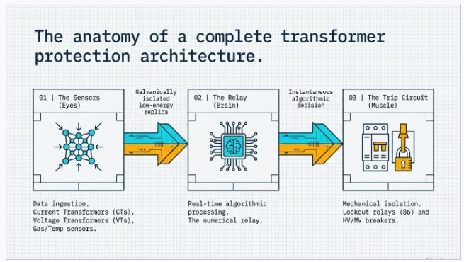
Power transformers are the most valuable single assets in most substations, and among the slowest to replace. A large unit can take a year or more to procure, and its loss can strand an entire load pocket or generation tie. That is why a transformer protection system is never an afterthought bolted onto the primary equipment — it is a designed system in its own right, one that continuously monitors the transformer and trips the associated circuit breakers to isolate the unit the instant a fault or abnormal condition appears. Done well, it protects the asset, the people around it, and the reliability of everything downstream.
This article walks through the anatomy of a complete transformer protection scheme from an engineering standpoint — the sensing chain, the protective functions, and the trip path — and then looks at what it actually takes to design, coordinate, and commission one in the field.
The Sensing Chain: CTs, VTs, and the Relay
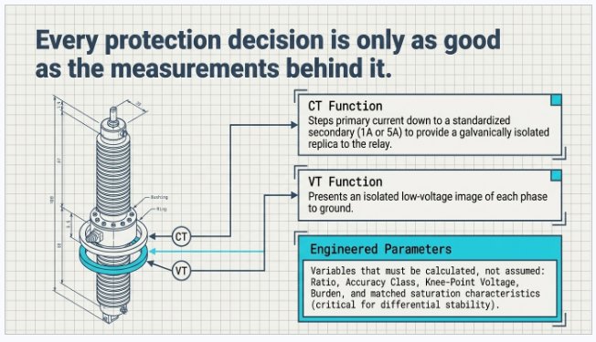
Every protection decision is only as good as the measurements behind it. Current transformers (CTs) on each phase step the primary current down to a standardized secondary (typically 1 A or 5 A) and provide a galvanically isolated, low-energy replica of the line current to the relay. Voltage transformers (VTs), likewise, present an isolated low-voltage image of each phase to ground. Getting this layer right is foundational: CT ratio and accuracy class, knee-point voltage, burden, and — critically for differential schemes — matched saturation characteristics all have to be engineered, not assumed.
The protection relay is the brain of the system. A modern numerical relay continuously samples the CT and VT inputs alongside temperature and gas sensors, runs the protective algorithms in real time, and issues a trip command when any element picks up and times out. A healthy relay does nothing visible for years; its value is entirely in the microseconds when it acts correctly — and in never acting when it shouldn’t.
The Protective Functions
A well-designed scheme layers several protection elements so that every credible fault has a fast primary response and a graded backup. The core functions for an oil-filled power transformer are:
- Differential protection (87T) — the primary internal-fault element. It compares the current entering and leaving the transformer; in a healthy unit these balance (after accounting for ratio, vector group, and tap), so any significant differential current signals a winding fault between phases or to earth. Percentage-restraint and harmonic blocking keep it stable through inrush and external faults.
- Restricted earth fault (REF / 64) — high-sensitivity detection of ground faults near the neutral, where differential sensitivity fades.
- Overcurrent and earth fault (50/51, 50N/51N) — protection against overload and short circuits, and time-graded backup to the differential and to downstream devices.
- Buchholz relay — a mechanical device in the pipe to the conservator that detects gas accumulation or oil surge from an incipient internal fault, providing a staged alarm (slow gas build-up) and trip (violent surge).
- Temperature monitoring — winding and top-oil temperature devices raise an alarm and, if the condition persists, trip — protecting insulation life from sustained overheating.
- Oil level indication — monitors the conservator level so that a low-oil condition raises an alarm before it can compromise cooling or dielectric strength.
The art is in coordination: each element must be sensitive enough to catch its target fault yet secure enough to ride through inrush, external faults, and CT saturation without a false trip. That balance is set by protection studies, not by default relay settings.
From Detection to Isolation: The Trip Circuit
Detection is only half the job. When any protective element operates, the relay energizes the trip circuit, which opens the transformer’s circuit breakers and disconnects the unit from the system. The integrity of this path deserves as much attention as the relay logic itself: trip-coil supervision, redundant DC supplies, lockout relays (86) where a manual reset is warranted, and clearly engineered breaker-failure backup all ensure that a valid trip command actually clears the fault. A protection scheme that detects perfectly but fails to trip has protected nothing.
Design and Installation: Where Engineering Earns Its Keep
Specifying the right relay is the easy part. A protection system that performs on the worst day of its life is the product of a disciplined engineering process:
1. System studies and modeling
Short-circuit, load-flow and protection-coordination studies define the fault duties and the settings envelope. At Keentel we model these in industry-standard tools — ETAP, SKM, PSCAD, and DIgSILENT — so that CT ratios, relay pickups, and time grading are derived from the actual network, not from templates.
2. Scheme and CT/VT design
Selecting CT class and knee-point voltage for the differential zone, defining the protection zones and their overlap, sizing VT burdens, and drawing the AC/DC schematics and wiring so the as-built matches the design intent.
3. Settings, coordination, and NERC compliance
Translating study results into relay settings files, verifying selectivity across every element, and — for bulk-power-system assets — documenting the basis to satisfy NERC PRC and O&P standards.
4. Commissioning and testing
Secondary injection to prove every element, primary injection and stability checks on the differential zone, trip-path verification through to the breaker, and functional testing of Buchholz, temperature, and oil-level trips before the unit is energized. Commissioning is where design assumptions meet reality — and where an experienced engineering partner prevents the costly surprises.
What a Complete Scheme Detects
Taken together, a properly engineered transformer protection system stands guard against the full range of failure modes: internal winding faults, overcurrent and short circuits, overheating, low oil level, internal gas or oil surge, and earth faults. Each has a dedicated element, and each element is coordinated with the others so that the fastest appropriate device clears the fault while backup remains ready.
Case Studies from the Field
The following engagements are drawn from Keentel Engineering’s protection and substation work. Client names and identifying details have been withheld; figures are representative of the outcomes achieved.
CASE STUDY 01 Curing Nuisance Trips on a Utility-Scale Solar Step-Up Transformer
Challenge: A 34.5/230 kV step-up transformer at a large PV plant tripped on differential protection during routine energization and after nearby external faults. Each event pulled the plant offline, and repeated inrush-driven misoperations were eroding the owner’s confidence in the scheme and their availability numbers.
Solution: Our engineers re-examined the differential zone end to end. CT ratios and knee-point voltages were checked against a fresh short-circuit model in ETAP, secondary wiring and polarity were verified, and the numerical relay’s percentage-restraint slope and second-harmonic blocking were retuned to distinguish magnetizing inrush from a true internal fault. Stability was then proven by primary injection across the zone.
Result: Nuisance trips on energization and through-faults were eliminated while full internal-fault sensitivity was preserved. The plant returned to its contractual availability target, and the owner adopted the retuned settings basis as a template across sister sites.
CASE STUDY 02 Modernizing Protection on an Aging 138 kV Substation
Challenge: A utility operated a substation whose transformer protection still relied on decades-old electromechanical relays. Spare parts were scarce, coordination had drifted as load grew, and the assets could no longer be shown to meet current NERC PRC requirements without a documented settings basis.
Solution: Keentel delivered a phased retrofit: a full protection-coordination study in SKM, replacement of the legacy relays with modern numerical devices providing 87T, REF, and 50/51 functions, redrawn AC/DC schematics, and a settings package with the calculations and margins documented for compliance. The cutover was sequenced to keep the substation in service throughout.
Result: Selectivity was restored across every element, obsolescence risk was removed, and the utility received an audit-ready compliance package. Protection operating times for close-in faults were reduced, lowering through-fault stress on the transformer.
CASE STUDY 03 Protection Design and Commissioning for a New BESS Interconnection
Challenge: A developer bringing a battery energy storage system online at a new point of interconnection needed a complete transformer protection scheme designed, coordinated, and commissioned to a tight energization deadline — with the interconnecting utility’s protection requirements to satisfy before approval.
Solution: Acting as owner’s engineer, our team designed the full scheme from the ground up: protection zones and CT/VT specification, differential and restricted earth fault elements, time-graded overcurrent backup, and a redundant trip path with trip-coil supervision and a lockout relay. We modeled fault duties, produced the settings, coordinated the relay philosophy with the utility, and led secondary- and primary-injection commissioning through to breaker trip.
Result: The scheme passed the utility’s witnessed testing on the first attempt and the asset energized on schedule. The documented design and test records shortened the interconnection approval and gave the developer a clean baseline for operations and maintenance.
Frequently asked questions
Q. What is the difference between differential (87T) and overcurrent (50/51) protection on a transformer?
Differential protection is a unit scheme: it responds only to faults inside the zone bounded by its CTs — that is, internal winding faults — and does so almost instantaneously with no need for time grading. Overcurrent protection responds to the magnitude of current regardless of where the fault is, so it serves as overload protection and as time-graded backup to the differential and to downstream devices. A complete scheme uses both: differential as the fast primary element, overcurrent as coordinated backup.
Q. Why does a differential relay need harmonic restraint?
When a transformer is energized, magnetizing inrush can draw a large current on the primary with no corresponding secondary current — which looks exactly like an internal fault to a simple differential comparison. Inrush is rich in second-harmonic content, so the relay uses second-harmonic blocking (and often fifth-harmonic restraint for overexcitation) to recognize inrush and hold off tripping, while still operating quickly for a genuine fault.
Q. Is a Buchholz relay still necessary if I have modern numerical protection?
Yes. The Buchholz relay detects incipient faults — slowly developing insulation breakdown or partial discharge — by sensing the gas they generate, often before the fault produces enough electrical signature for the differential element to act. It also detects loss of oil and violent oil surge. It is a mechanical, independent line of defense that complements, rather than duplicates, the numerical relay, which is why oil-filled power transformers are typically fitted with both.
Q. How often should transformer protection settings be reviewed?
Settings should be revisited whenever the surrounding network changes materially — new generation or load, altered fault levels, reconfiguration, or a transformer replacement — and periodically as part of a maintenance and compliance program. For bulk-power-system assets, NERC PRC standards drive a documented review and testing cadence; even where they don’t apply, a coordination review every few years is sound practice because fault duties and coordination margins drift over time.
Q. What is restricted earth fault (REF) protection and when do I need it?
REF is a high-sensitivity element that protects against ground faults near the transformer neutral, where the current available to the phase differential element is small and its sensitivity falls off. By comparing neutral current with the residual of the phase CTs, REF detects winding-to-earth faults close to the star point that a standard differential might miss. It is commonly applied on solidly or impedance-earthed windings where earth-fault sensitivity matters.
Q. What does commissioning a transformer protection system actually involve?
Commissioning proves that the design works as installed. It typically includes secondary injection to verify each protective element and its settings, primary injection and a stability check to confirm the differential zone is correctly wired and polarized, verification of the complete trip path through to the breaker (including trip-coil supervision and lockout), and functional testing of the mechanical trips — Buchholz, winding and oil temperature, and oil level — before the transformer is energized.
Q. Can Keentel work as an owner’s engineer rather than replacing our in-house team?
Yes. Much of our protection work is delivered in an owner’s-engineer capacity — providing independent design review, studies, settings, and commissioning oversight that sit alongside a client’s own staff or EPC. The goal is to bring specialist protection expertise and an independent check to the project without displacing the people who know the asset best.
Why Keentel Engineering
Keentel Engineering delivers end-to-end electrical power engineering across high-, extra-high-, and medium-voltage systems, with more than three decades of experience in substation design, protection and control, and interconnection. Our teams in Tampa, Austin, Sacramento, and Baltimore support utilities, independent power producers, EPCs, and developers — from the initial system studies through detailed protection design settings, and field commissioning.
Whether you are protecting a new step-up transformer for a utility-scale solar or BESS project, modernizing protection on an aging substation, or adding an owner’s engineer to keep a project honest, we design protection systems that are sensitive, secure, and compliant — built to protect not just equipment, but reliability, uptime, and the people who depend on it.

About the Author:
Sandip "Sonny" R. Patel, P.E.
IEEE Senior Member · Founder & CEO, Keentel Engineering
In 1995, Sonny Patel earned his Electrical Engineering degree from the University of Illinois. But degrees don't build legacies — action does.
For three decades, he has worked the power industry from every side of the table: 16 years as a utility engineer at Exelon/Commonwealth Edison; generation leadership across hydroelectric, industrial steam turbine, and a 9 GW renewable fleet; NERC Regional Entity Senior Compliance Engineer and Audit Team Lead, auditing some of the nation's largest utilities; and testing and commissioning lead on equipment up to 765 kV — the very top of the North American grid.Utility. Generator. Regulator. Consultant. Few engineers have seen all four seats. Fewer still have sat in them.
His experience spans nuclear, hydro, conventional generation, renewables, oil and gas, mining — and today's data centers, where he is authoring a three-book series on data center design. He is a Licensed Professional Engineer in six states and a Licensed Electrical Contractor in Florida (Unlimited EC) — he doesn't just design the work; he's qualified to stand behind its execution.Today, as Founder and CEO of Keentel Engineering, Sonny leads a nationwide team of engineers delivering substation design, power system studies, NERC compliance, and commissioning — done right, coast to coast.Three decades. Every side of the table. One standard: accountable engineering.
Services

Let's Discuss Your Project
Let's book a call to discuss your electrical engineering project that we can help you with.
About the Author:
Sandip "Sonny" R. Patel, P.E.
IEEE Senior Member · Founder & CEO, Keentel Engineering
In 1995, Sonny Patel earned his Electrical Engineering degree from the University of Illinois. But degrees don't build legacies — action does.
For three decades, he has worked the power industry from every side of the table: 16 years as a utility engineer at Exelon/Commonwealth Edison; generation leadership across hydroelectric, industrial steam turbine, and a 9 GW renewable fleet; NERC Regional Entity Senior Compliance Engineer and Audit Team Lead, auditing some of the nation's largest utilities; and testing and commissioning lead on equipment up to 765 kV — the very top of the North American grid.
Utility. Generator. Regulator. Consultant. Few engineers have seen all four seats. Fewer still have sat in them.
His experience spans nuclear, hydro, conventional generation, renewables, oil and gas, mining — and today's data centers, where he is authoring a three-book series on data center design. He is a Licensed Professional Engineer in six states and a Licensed Electrical Contractor in Florida (Unlimited EC) — he doesn't just design the work; he's qualified to stand behind its execution.
Today, as Founder and CEO of Keentel Engineering, Sonny leads a nationwide team of engineers delivering substation design, power system studies, NERC compliance, and commissioning — done right, coast to coast.Three decades. Every side of the table. One standard: accountable engineering.
Leave a Comment
Thank you for contacting us.
We will get back to you as soon as possible.
We will get back to you as soon as possible.
Oops, there was an error sending your message.
Please try again later.
Please try again later.
Related Posts
By SANDIP R PATEL
•
September 20, 2026
Learn CHP load following and island detection engineering for campus plants, including protection, controls, power studies, and grid transition design.
By SANDIP R PATEL
•
September 20, 2026
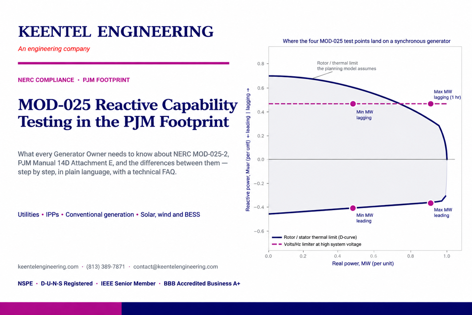
Understand NERC PRC-029-1 requirements for inverter-based resources, ride-through performance, grid reliability, compliance testing, and modeling.
By SANDIP R PATEL
•
September 19, 2026
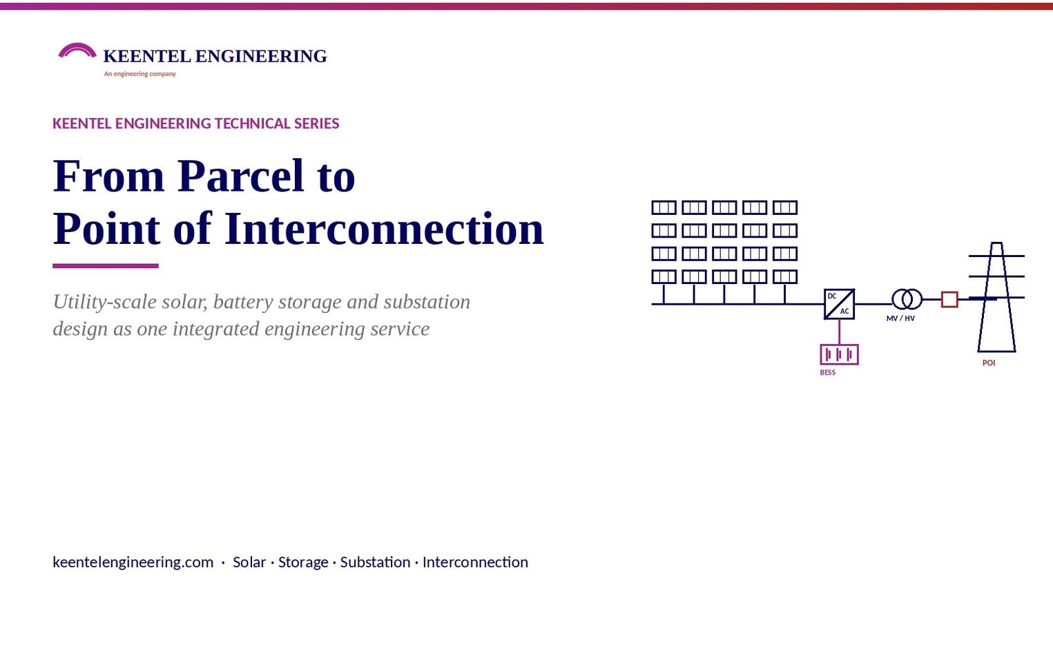
Explore utility scale solar engineering from site assessment to POI interconnection, including PV design, BESS, substation and grid studies.
By SANDIP R PATEL
•
September 18, 2026
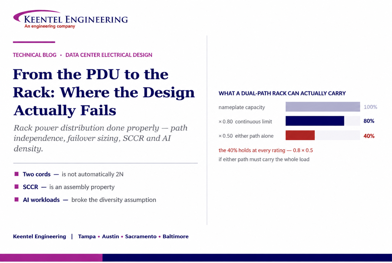
Learn how to size rack power distribution, PDU and RPP systems for continuous loads, A/B redundancy, failover capacity, SCCR and high-density AI data centers.
By SANDIP R PATEL
•
September 18, 2026
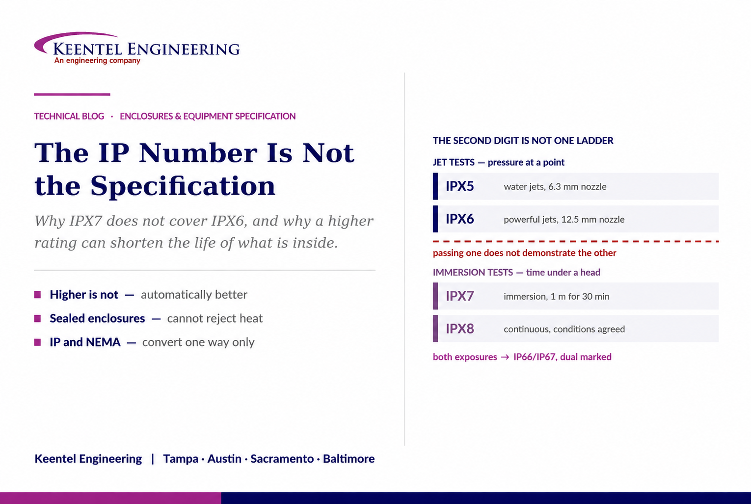
Learn why IP ratings like IP66, IP67, and IP68 do not tell the full story. Understand enclosure selection, NEMA differences, heat, corrosion, and protection.
By SANDIP R PATEL
•
September 9, 2026
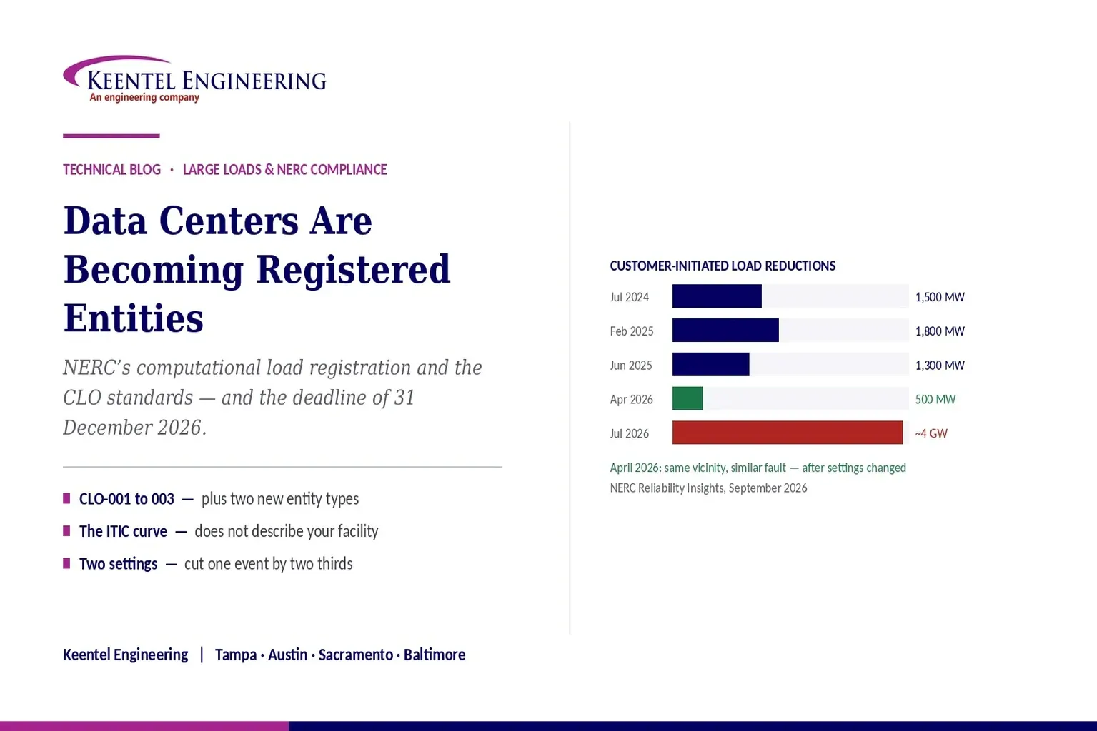
Learn how NERC computational load registration impacts data centers, CLO standards, ride-through requirements, modeling, and grid reliability compliance.
By SANDIP R PATEL
•
September 7, 2026
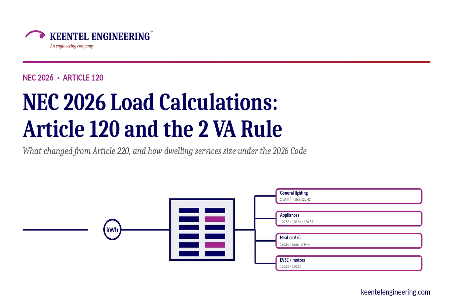
Learn NEC 2026 load calculations, Article 120 changes, the 2 VA rule, EV charging requirements, service sizing, and dwelling calculation methods.
By SANDIP R PATEL
•
September 7, 2026
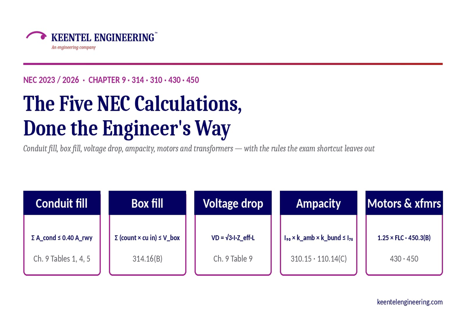
Learn five essential NEC calculations covering conduit fill, voltage drop, ampacity, motor circuits, and transformer protection with engineering examples.
By SANDIP R PATEL
•
September 7, 2026
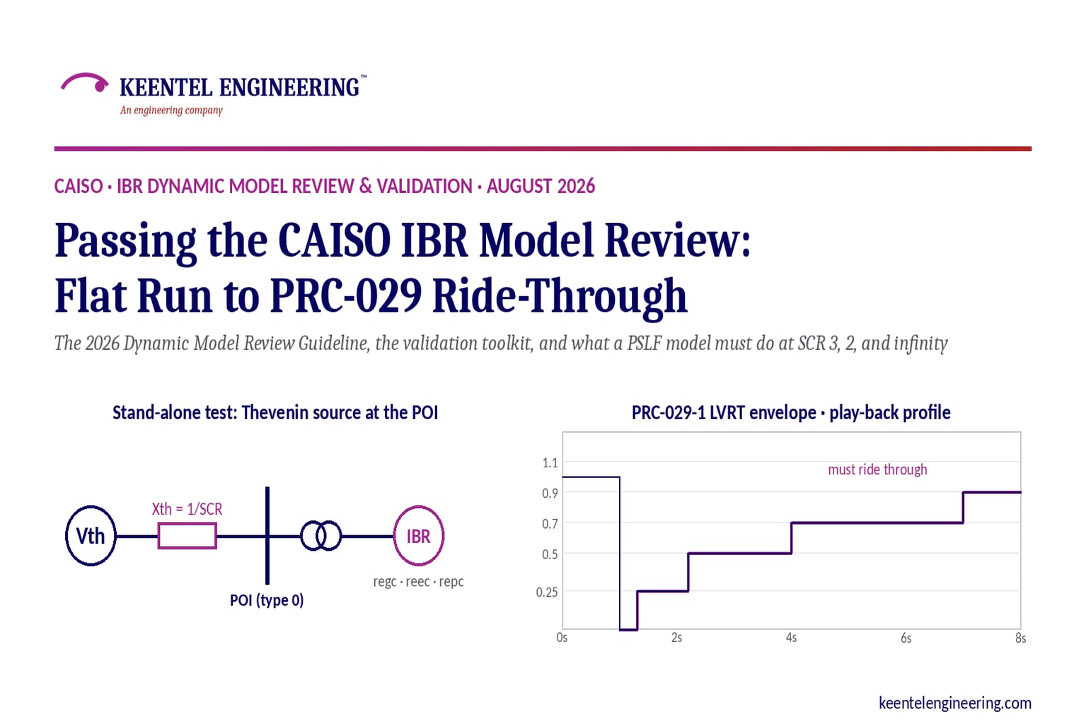
Learn how CAISO reviews IBR models using PSLF validation, PRC-029-1 ride-through requirements, WECC models, and inverter resource compliance testing.





