
A Coordinated Electric System Interconnection Review—the utility’s deep-dive on technical and cost impacts of your project.
Challenge: Frequent false tripping using conventional electromechanical relays
Solution: SEL-487E integration with multi-terminal differential protection and dynamic inrush restraint
Result: 90% reduction in false trips, saving over $250,000 in downtime
ERCOT enforces all of the above through simulation, which means your model is your compliance case. The bar is now high:
- Whole-facility scope. The model must represent everything the IT load, the UPS and power conversion, the cooling plant, the protection and control systems in formats compatible with ERCOT's study platforms (PSS/E, PSCAD, TSAT).
- Real control loops, not approximations. Generic textbook representations are unacceptable. The model must capture the actual inner control behavior of your power electronics.
- Hardware-validated converter models. For electronic loads, the PSCAD model must be benchmarked against actual hardware testing including voltage ride-through and subsynchronous response. A model assembled from standard PSCAD library blocks fails by definition, because a generic block has never been tested against your vendor's hardware. The good news: validation is a hardware-type test, so results for a given converter product are reusable across every facility that uses it.
- Format migration. Facilities that previously submitted the older composite load model (CMLD) format must transition to EPRI's PERC1 format.
- Three checkpoints. Models are reviewed before the stability study begins (no model, no study), before each quarterly stability assessment, and for electronic loads one final time before energization, when you must submit as-built models with a documented comparison against the previously studied data and a sworn attestation that the model matches actual field settings. ERCOT's review takes 10 business days, extendable by 20 put it on your critical path.
- A living obligation. Change your technology, controls, or relay settings in a way that affects ride-through including converting a crypto mining site to an AI data center — and you've triggered a new interconnection study, even if your megawatts don't change.
| Parameter | Detail |
|---|---|
| System | 230 kV / 138 kV transmission corridors, wind and wet-snow icing exposure |
| Data basis | 15 years of minute-resolution forced-outage records + regional weather observations |
| Core methods | Event grouping, MVA performance curves, time-to-95%-restore, area outage rate curves, fragility modeling, rerun-history benefits, exceedance and log-domain risk metrics |
| Headline result | ≈85% of maximum resilience benefit at 60% of original capital; worst-event restoration window cut from 11 days to 5 in rerun-history terms |
| Decision supported | Capital portfolio selection; resilience plan filing; post-investment verification framework |
| System / Topic | Governing Standard(s) | What It Controls |
|---|---|---|
| Overall plant electrical distribution | IEEE 141 (Red Book); IEEE 666 | Distribution architecture, voltage selection, design of generating station auxiliary service systems |
| Power system studies | IEEE 399 (Brown Book); IEEE 551 | Load flow, symmetrical/asymmetrical short circuit, motor starting methodologies down to the lowest LV panelboard |
| Protection & coordination | IEEE 242 (Buff Book); IEEE 3004.5; IEEE C37 series | Generator relaying (21, 59N, 87G), time-current coordination, selective clearing between LV and MV tiers |
| GSU / UAT / SST transformers | IEEE C57.12.00 and C57 family | Transformer ratings, impedance, testing, loading |
| HV switchyard breakers | IEEE C37.06 | AC high-voltage circuit breaker preferred ratings |
| MV switchgear (13.8 kV) | IEEE C37.20.2; IEEE C37.20.7 | Metal-clad construction, compartmentalization, vacuum breakers; arc-resistant design with plenum venting |
| MV cable | UL 1072; ICEA S-93-639 (NEMA WC 74) | Type MV-105 shielded cable, 133% insulation level for HRG systems |
| LV switchgear (480 V) | IEEE C37.13; UL 1558 | Metal-enclosed LV power circuit breaker switchgear to 635 V, draw-out ACBs with electronic trip units |
| Motor control centers | UL 845; NEMA ICS 18 | LV-MCC construction, MCCB/MCP protection for motors under ~200 HP |
| Motors | NEMA MG-1 | Motor performance, starting characteristics, service factors |
| DC & battery systems | IEEE 485; IEEE 946 | Lead-acid battery sizing (125/250 VDC), DC auxiliary system design |
| Grounding | IEEE 80; IEEE 142 (Green Book) | Ground grid step/touch potential limits; system grounding including high-resistance grounding |
| Lightning protection | IEEE 998 | Direct-stroke shielding of switchyard and outdoor generator structures |
| Arc flash & electrical safety | IEEE 1584; NFPA 70E | Incident energy calculation; worker safety boundaries and PPE |
| Fire protection | NFPA 850 | Fire protection and risk management for combustion turbine generating plants |
| Installation code | NEC (NFPA 70); NESC | Wiring methods inside the plant fence; overhead/outdoor clearances at the switchyard |
| Interconnection & compliance | FERC LGIP; NERC MOD-025/026/027, PRC-019/024/029, FAC-008 | Interconnection process, model validation, protection/ride-through coordination, facility ratings |
| IFC / Construction Deliverable | Purpose |
|---|---|
| Stamped IFC packages | Legal basis for construction; P.E. responsible charge |
| Final relay settings & TCCs | Protection as-installed matches the coordination study |
| Calculation archive | Owner records; NERC audit evidence trail |
| Commissioning procedures | Safe, sequenced energization; MOD field testing |
| Construction support | RFIs, field changes, FAT/SAT witness |
| As-builts & model handoff | Operating baseline; future study currency |
| Metric | Outcome |
|---|---|
| Defects found pre-occupancy | Three topology defects and one settings-mismatch family corrected before load migration; the shared-switchboard defect alone would have invalidated the concurrently-maintainable claim on day one |
| IST findings | Fourteen additional discrepancies surfaced under scenario testing (control logic, alarm mapping, one generator sequencing fault) — all closed before handover instead of during operations |
| Black-building test | Passed on second execution; the first attempt exposed the generator sequencing fault under true block load, exactly the failure the compressed plan would never have found |
| Handover quality | Operations team certified on the actual failure scenarios; corrected EOPs and settings documentation delivered as controlled documents |
| Business outcome | Occupancy proceeded three weeks behind the original date — against an independent estimate that the uncorrected sequencing fault carried a high probability of a full facility outage within the first year |
Part 2 — Frequently Asked Questions: Large Load Interconnection
| Contact | Details |
|---|---|
| Headquarters | 400 N Ashley Dr STE 2600, Tampa, FL 33602 |
| Phone | (813) 389-7871 |
| contact@keentelengineering.com | |
| Florida Firm Registration | No. 36853 |
| Additional Offices | Austin, TX • Sacramento, CA • Baltimore, MD |
| Who | Acronym | Plain-English Role |
|---|---|---|
| ERCOT | — | The grid's air traffic controller. It doesn't own power lines or plants; it directs the flow of electricity across most of Texas and referees the admission process for new generators. |
| Interconnecting Entity | IE | You — the developer or owner trying to connect a new plant (or significantly modify an existing one). You file the application and drive the process. |
| Resource Entity | RE | The registered owner/operator of the generator once it becomes an official market participant. Often the same company as the IE, wearing a different hat. |
| Qualified Scheduling Entity | QSE | Your plant's voice on the grid. The QSE handles round-the-clock communications with ERCOT — telemetry, schedules, dispatch instructions. Every generator must have one. |
| Transmission Service Provider | TSP | The utility that owns the wires and substation you'll connect to. The TSP runs your detailed study, builds the connection facilities, and signs your interconnection contract. |
| RIOO-IS | — | ERCOT's online portal where the whole process lives — applications, documents, status tracking, and checklists all flow through it. |
| Who | Acronym | Plain-English Role |
|---|---|---|
| ERCOT | — | The grid's air traffic controller. It doesn't own power lines or plants; it directs the flow of electricity across most of Texas and referees the admission process for new generators. |
| Interconnecting Entity | IE | You — the developer or owner trying to connect a new plant (or significantly modify an existing one). You file the application and drive the process. |
| Resource Entity | RE | The registered owner/operator of the generator once it becomes an official market participant. Often the same company as the IE, wearing a different hat. |
| Qualified Scheduling Entity | QSE | Your plant's voice on the grid. The QSE handles round-the-clock communications with ERCOT — telemetry, schedules, dispatch instructions. Every generator must have one. |
| Transmission Service Provider | TSP | The utility that owns the wires and substation you'll connect to. The TSP runs your detailed study, builds the connection facilities, and signs your interconnection contract. |
| RIOO-IS | — | ERCOT's online portal where the whole process lives — applications, documents, status tracking, and checklists all flow through it. |
| Who | Acronym | Plain-English Role |
|---|---|---|
| ERCOT | — | The grid's air traffic controller. It doesn't own power lines or plants; it directs the flow of electricity across most of Texas and referees the admission process for new generators. |
| Interconnecting Entity | IE | You — the developer or owner trying to connect a new plant (or significantly modify an existing one). You file the application and drive the process. |
| Resource Entity | RE | The registered owner/operator of the generator once it becomes an official market participant. Often the same company as the IE, wearing a different hat. |
| Qualified Scheduling Entity | QSE | Your plant's voice on the grid. The QSE handles round-the-clock communications with ERCOT — telemetry, schedules, dispatch instructions. Every generator must have one. |
| Transmission Service Provider | TSP | The utility that owns the wires and substation you'll connect to. The TSP runs your detailed study, builds the connection facilities, and signs your interconnection contract. |
| RIOO-IS | — | ERCOT's online portal where the whole process lives — applications, documents, status tracking, and checklists all flow through it. |
| Who | Acronym | Plain-English Role |
|---|---|---|
| ERCOT | — | The grid's air traffic controller. It doesn't own power lines or plants; it directs the flow of electricity across most of Texas and referees the admission process for new generators. |
| Interconnecting Entity | IE | You — the developer or owner trying to connect a new plant (or significantly modify an existing one). You file the application and drive the process. |
| Resource Entity | RE | The registered owner/operator of the generator once it becomes an official market participant. Often the same company as the IE, wearing a different hat. |
| Qualified Scheduling Entity | QSE | Your plant's voice on the grid. The QSE handles round-the-clock communications with ERCOT — telemetry, schedules, dispatch instructions. Every generator must have one. |
| Transmission Service Provider | TSP | The utility that owns the wires and substation you'll connect to. The TSP runs your detailed study, builds the connection facilities, and signs your interconnection contract. |
| RIOO-IS | — | ERCOT's online portal where the whole process lives — applications, documents, status tracking, and checklists all flow through it. |
| Who | Acronym | Plain-English Role |
|---|---|---|
| ERCOT | — | The grid's air traffic controller. It doesn't own power lines or plants; it directs the flow of electricity across most of Texas and referees the admission process for new generators. |
| Interconnecting Entity | IE | You — the developer or owner trying to connect a new plant (or significantly modify an existing one). You file the application and drive the process. |
| Resource Entity | RE | The registered owner/operator of the generator once it becomes an official market participant. Often the same company as the IE, wearing a different hat. |
| Qualified Scheduling Entity | QSE | Your plant's voice on the grid. The QSE handles round-the-clock communications with ERCOT — telemetry, schedules, dispatch instructions. Every generator must have one. |
| Transmission Service Provider | TSP | The utility that owns the wires and substation you'll connect to. The TSP runs your detailed study, builds the connection facilities, and signs your interconnection contract. |
| RIOO-IS | — | ERCOT's online portal where the whole process lives — applications, documents, status tracking, and checklists all flow through it. |
| Who | Acronym | Plain-English Role |
|---|---|---|
| ERCOT | — | The grid's air traffic controller. It doesn't own power lines or plants; it directs the flow of electricity across most of Texas and referees the admission process for new generators. |
| Interconnecting Entity | IE | You — the developer or owner trying to connect a new plant (or significantly modify an existing one). You file the application and drive the process. |
| Resource Entity | RE | The registered owner/operator of the generator once it becomes an official market participant. Often the same company as the IE, wearing a different hat. |
| Qualified Scheduling Entity | QSE | Your plant's voice on the grid. The QSE handles round-the-clock communications with ERCOT — telemetry, schedules, dispatch instructions. Every generator must have one. |
| Transmission Service Provider | TSP | The utility that owns the wires and substation you'll connect to. The TSP runs your detailed study, builds the connection facilities, and signs your interconnection contract. |
| RIOO-IS | — | ERCOT's online portal where the whole process lives — applications, documents, status tracking, and checklists all flow through it. |
| Who | Acronym | Plain-English Role |
|---|---|---|
| ERCOT | — | The grid's air traffic controller. It doesn't own power lines or plants; it directs the flow of electricity across most of Texas and referees the admission process for new generators. |
| Interconnecting Entity | IE | You — the developer or owner trying to connect a new plant (or significantly modify an existing one). You file the application and drive the process. |
| Resource Entity | RE | The registered owner/operator of the generator once it becomes an official market participant. Often the same company as the IE, wearing a different hat. |
| Qualified Scheduling Entity | QSE | Your plant's voice on the grid. The QSE handles round-the-clock communications with ERCOT — telemetry, schedules, dispatch instructions. Every generator must have one. |
| Transmission Service Provider | TSP | The utility that owns the wires and substation you'll connect to. The TSP runs your detailed study, builds the connection facilities, and signs your interconnection contract. |
| RIOO-IS | — | ERCOT's online portal where the whole process lives — applications, documents, status tracking, and checklists all flow through it. |
Protection Design
Reactors in Substations
Aug 8, 2026 | Blog
Part 1 — Reactors in Substations: An In-Depth Technical Guide
1. Introduction
Ask a room of graduate engineers what a substation does and most will describe transformers stepping voltage up and down, breakers clearing faults, and busbars tying everything together. Far fewer will mention the tall, ribbed stacks of coils quietly doing some of the most important work on the site: the reactors. Yet on high-voltage (HV) and extra-high-voltage (EHV) networks, reactors are the difference between a grid that holds a stable voltage profile and one that drifts dangerously high at light load, and between a fault current the switchgear can interrupt and one that exceeds its rating.
A reactor is, at heart, a deliberately engineered inductor: a coil that stores energy in its magnetic field and opposes changes in the current flowing through it. That simple property — impedance that rises with frequency and current — is put to work in several distinct ways across a substation. Reactors absorb surplus reactive power to pull voltage back down, they add series impedance to throttle short-circuit current, and they sit in transformer and generator neutrals to keep earth-fault currents within safe limits.
This article, prepared by the engineering team at Keentel Engineering, walks through the theory, the hardware, the standards and the selection logic behind substation design . It is written for practising power, transmission and protection engineers, but is structured so that newer team members can follow the reasoning from first principles. A detailed FAQ and three anonymized field case studies follow the main text.
2. First Principles: What a Reactor Actually Is
A reactor is an inductive device — an inductor with inductance L — connected into a power circuit to introduce a controlled inductive reactance. At the system frequency f, that reactance is XL = 2πfL, measured in ohms. Because the impedance is almost purely inductive, the current through a reactor lags the voltage across it by close to 90 degrees, and the device absorbs reactive power (measured in VAr) rather than dissipating real power.
The reactive power a shunt reactor absorbs is Q = V2/XL, where V is the applied voltage. Two consequences follow immediately and matter enormously in practice. First, absorption scales with the square of voltage, so a reactor draws disproportionately more reactive power exactly when the system voltage rises — which is precisely the condition it is installed to correct. Second, because energy is stored in the magnetic field (E = ½LI2), a reactor resists sudden changes in current, which is why series and neutral reactors are so effective at limiting the rate-of-rise and magnitude of fault current.
Unlike a transformer, an ideal reactor has no secondary winding and no intended power transfer; its job is to present impedance. Real reactors do dissipate a small amount of real power as copper (I²R) losses in the winding and, where an iron core is used, as core losses — but these are parasitic, not the purpose. A well-designed EHV shunt reactor typically operates at very low loss relative to its reactive rating, and quality factor (Q = X/R) is high.
3. The Reactive-Power Problem Reactors Solve
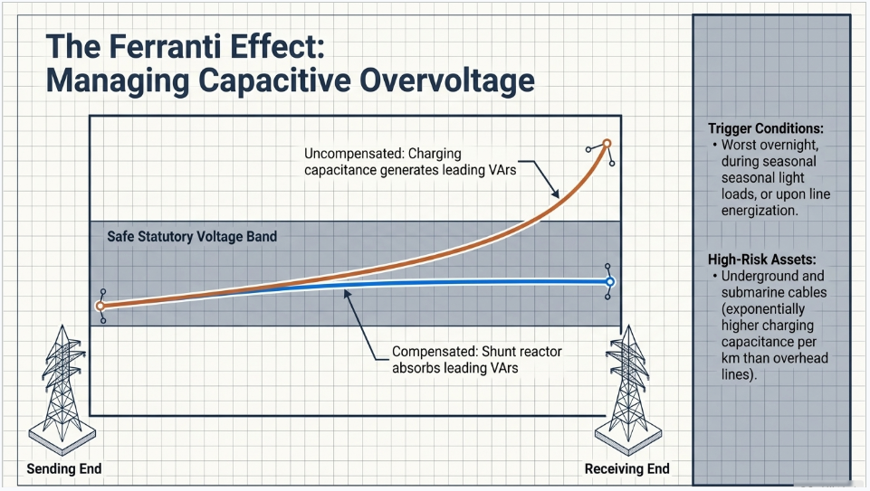
To understand why utilities spend heavily on reactors, you have to understand where surplus reactive power comes from. Every transmission line and cable has distributed shunt capacitance to earth. When a line is lightly loaded or energized but nearly open, this capacitance generates leading reactive power (line charging). With little load current to consume it, that reactive power flows back into the system and pushes the receiving-end voltage above the sending-end voltage — the classic Ferranti effect. On long EHV overhead lines and on any significant length of HV cable, the rise can be severe enough to threaten insulation and shorten equipment life.
The effect is worst at exactly the times operators least want it: overnight and during light-load seasons, and immediately after a line is switched in before it is loaded. Underground and submarine cables are especially prone because their charging capacitance per kilometre is far higher than an overhead line’s, which is why cable circuits almost always require dedicated compensation.
A shunt reactor is the direct antidote. Connected in parallel with the line or busbar, it absorbs the surplus leading reactive power, flattening the voltage profile and keeping the network within its statutory voltage band. Where the reactive demand varies through the day, variable shunt reactors (VSRs) with on-load tap changers, or switched banks, let operators dial the compensation up and down rather than being stuck with a fixed value.
4. Why Reactors Are Used — The Four Core Functions
The infographic that prompted this article distils the role of reactors into four functions. Each deserves expansion.
4.1 Controlling overvoltage
Under light-load or no-load conditions, and following load rejection or line energization, system voltage can climb above safe limits. Shunt reactors absorb the excess reactive power and hold voltage within the permitted band — protecting insulation, surge arresters and connected plant, and avoiding the accelerated ageing that sustained overvoltage causes. On EHV lines a portion of the reactor may be permanently connected, with additional steps switched in as conditions demand.
4.2 Limiting fault current
As networks grow and more generation and interconnection are added, the available short-circuit current at a busbar rises. If it exceeds the breaking capacity of the installed switchgear, the switchgear can no longer safely interrupt a fault. Rather than replacing every breaker — hugely expensive and disruptive — engineers insert a series (current-limiting) reactor to add impedance in the fault path. The reactor reduces the peak and RMS fault current to a level the existing switchgear can handle, buying capacity and protecting the whole downstream chain.
4.3 Improving system stability
By regulating reactive power and current flows, reactors help hold voltage steady across a range of operating conditions. Stable voltage supports both steady-state and transient stability, keeps power-transfer margins healthy on heavily used corridors, and reduces the risk of voltage collapse. In FACTS devices such as Static VAr Compensators (SVCs), thyristor-controlled reactors provide the continuously variable inductive element that makes fast, closed-loop voltage regulation possible.
4.4 Protecting equipment
Every function above ultimately protects hardware. By keeping voltage within limits and fault current below ratings, reactors reduce electrical and thermal stress on transformers, cables, breakers and instrument transformers. Lower stress means longer service life, fewer forced outages and better overall reliability — a direct return on the capital spent on the reactor.
5. Types of Reactor and Where Each Is Used
Reactors are classified primarily by how they are connected and what they are asked to do. The three shown in the source infographic are the workhorses; several specialized types round out the family.
| Reactor type | Connection & function |
|---|---|
| Shunt reactor | Connected in parallel with the line or busbar. Absorbs surplus (leading) reactive power to control overvoltage and flatten the voltage profile, especially at light load and on long lines and cables. |
| Series / current-limiting reactor | Connected in series with the line, feeder or bus-tie. Adds impedance to limit short-circuit (fault) current so existing switchgear stays within its interrupting rating. |
| Neutral grounding reactor | Connected between a transformer or generator neutral and earth. Limits line-to-earth (single-phase) fault current and controls the earthing regime, protecting the neutral and reducing step/touch potentials. |
| Smoothing reactor | Used on HVDC links in series with the DC line. Smooths ripple in the direct current, limits DC fault current rate-of-rise and helps prevent commutation failure. |
| Filter / damping reactor | Paired with capacitors in harmonic filters and capacitor banks to tune resonance and limit capacitor inrush and switching transients. |
| Thyristor-controlled reactor (TCR) | The controllable inductive branch of an SVC. Thyristor firing angle varies the effective reactance continuously for fast, dynamic reactive-power and voltage control. |
6. Construction: Air-Core vs Iron-Core (Oil-Immersed) Reactors
Reactors are built in two broad construction families, and the choice drives footprint, losses, linearity and cost.
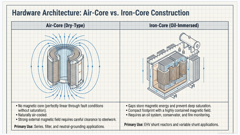
Air-core (dry-type) reactors: use no magnetic core; the inductance is set purely by the coil geometry. With no iron to saturate, their inductance is essentially linear right through fault conditions — a decisive advantage for current-limiting duty, where you need the reactance to hold up during a heavy short circuit. They are typically wound as encapsulated, self-supporting cylinders, are naturally air-cooled, and are common for series, filter, damping and many neutral-grounding applications. Their trade-off is a strong external magnetic field, so clearances to steelwork and adjacent phases must be managed to avoid stray heating.
Oil-immersed, gapped-iron-core reactors: use a magnetic core with precisely engineered air gaps, immersed in a tank of insulating oil much like a transformer. The gaps store most of the magnetic energy and keep the core out of deep saturation, giving a compact, low-loss, well-shielded device with contained magnetic field. This construction dominates large EHV shunt-reactor applications (for example 400 kV and 765 kV line reactors) and is the basis of variable shunt reactors, where an on-load tap changer varies the MVAr rating. The trade-off is the oil system, conservator and associated fire, cooling and monitoring provisions.
7. Capacitor vs Reactor — Two Sides of Reactive Power
Because both appear in the same reactive-compensation conversation, it is worth being precise about how a reactor and a capacitor differ. They are complementary opposites: one supplies reactive power, the other absorbs it.
| Attribute | Shunt capacitor | Shunt reactor |
|---|---|---|
| Reactive power | Supplies (generates) reactive power — like a pump adding flow. | Absorbs (consumes) reactive power — like a controlled restriction slowing the flow. |
| Effect on voltage | Raises voltage; corrects lagging power factor under heavy load. | Lowers voltage; corrects overvoltage at light load and on long lines/cables. |
| Typical need | Peak/heavy-load periods, industrial power-factor correction. | Light-load/no-load periods, line energization, cable circuits. |
| Nature | Capacitive — current leads voltage. | Inductive — current lags voltage. |
In practice many substations carry both, sometimes switched dynamically, so operators can add or remove VAr in either direction as load swings through the day. The art of reactive planning is matching the right device — and the right switching strategy — to the network’s daily and seasonal profile.
8. Standards, Ratings and Selection
Reactor specification is governed by international and national standards, and getting the specification right is where an experienced engineering partner earns their keep.
- IEC 60076-6: “Power transformers – Part 6: Reactors” — the principal international standard covering shunt, series, neutral-earthing, damping, filter, smoothing and arc-suppression reactors, including rating, tolerances, losses, temperature rise and testing.
- IEEE C57.16: requirements, terminology and test code for dry-type (air-core) series-connected reactors — the reference for current-limiting reactor duty in North American practice.
- IEEE C57.21: requirements, terminology and test code for shunt reactors rated over 500 kVA.
- IEEE C57.32: requirements, terminology and test procedures for neutral grounding devices, including neutral grounding reactors.
Beyond picking a standard, a sound specification pins down the parameters that determine whether the reactor does its job and survives its environment:
- Rated voltage and system parameters — nominal and maximum system voltage, frequency, insulation level (BIL) and connection (single- or three-phase).
- Reactive rating (MVAr) or reactance (ohms/mH) — for shunt reactors the MVAr to be absorbed; for series/neutral reactors the ohmic value needed to bring fault current within target.
- Thermal and short-time current ratings — continuous current plus the short-circuit current the reactor must withstand mechanically and thermally for the specified duration.
- Linearity and saturation behaviour — critical for current-limiting reactors, which must keep their reactance during the fault they are limiting.
- Losses and Q factor, noise, and magnetic-field clearances — driving efficiency, environmental compliance and physical layout.
- Construction and cooling — air-core vs oil-immersed, indoor vs outdoor, and the seismic, altitude and pollution conditions of the site.
9. Applications Across the Network
Reactors appear wherever reactive power or fault current must be managed. Their headline applications include voltage control on transmission corridors, power-factor and reactive management, fault-current limitation at growing substations, and system stability support. They are integral to HVDC schemes — as DC smoothing reactors — and to FACTS devices such as SVCs and STATCOM-adjacent filter branches, where they provide the inductive element for dynamic compensation. On distribution and industrial systems, neutral grounding reactors control earth-fault current, and filter reactors tame harmonics and capacitor switching transients.
10. Key Takeaway
A reactor is an inductive device used to absorb reactive power, control voltage, limit fault current and improve the reliability and safety of the power system. It is the quiet counterpart to the capacitor: where the capacitor pushes voltage up and supplies reactive power under load, the reactor pulls voltage down and absorbs reactive power at light load, and — in series or neutral form — throttles fault current to protect the switchgear around it. Specified correctly against the right standard and matched to the network’s real operating profile, reactors deliver outsized value for a comparatively modest capital outlay. That specification, testing and integration work is exactly where Keentel Engineering supports utilities and industrial operators.
Part 2 — Field Case Studies
The following three case studies are anonymized and composited from typical substation engineering assignments. Site names, exact ratings and locations have been changed or generalized to protect client confidentiality; they are presented to illustrate how reactor selection plays out in practice.
Case Study 1 — Taming Light-Load Overvoltage on a 400 kV Corridor
| Sector | Transmission utility (EHV) |
|---|---|
| Challenge | Sustained overvoltage at light load on a long 400 kV line |
| Solution | Oil-immersed variable shunt reactor with neutral reactor |
Background
A regional transmission operator commissioned a roughly 220 km, 400 kV double-circuit line to move bulk power from a new generation hub to a load centre. Within weeks of energization, the control centre logged receiving-end voltages climbing above 420 kV during overnight and weekend light-load periods. Operators were manually opening one circuit at night to relieve the rise — an unsustainable workaround that reduced redundancy and risked the very supply security the line was built to improve.
Investigation
Keentel Engineering’s study confirmed a textbook Ferranti effect: the line’s distributed charging capacitance was generating a large surplus of leading reactive power that, at light load, pushed the far-end voltage up. Load-flow analysis across the daily and seasonal load curve quantified the surplus VAr and showed that a fixed reactor sized for the worst night would over-compensate during shoulder periods, dragging voltage too low and complicating power-factor management.
Solution
The recommendation was a three-phase, oil-immersed variable shunt reactor connected to the line, rated to absorb the peak surplus reactive power, with an on-load tap changer to trim the MVAr continuously as conditions changed. A small neutral grounding reactor was added to support single-pole auto-reclosing by helping extinguish the secondary arc during transient single-phase faults. Specification followed IEC 60076-6 and the utility’s insulation-coordination practice, with surge arresters and a defined magnetic-clearance layout.
Outcome
- Receiving-end voltage held within the statutory band across all load conditions, eliminating the nightly manual circuit-opening.
- Both circuits remained in service continuously, restoring full n-1 redundancy on the corridor.
- The variable rating let operators fine-tune compensation seasonally without switching whole banks, improving reactive-power efficiency.
- Reduced sustained overvoltage lowered insulation stress on line and substation plant, supporting longer asset life.
Case Study 2 — Buying Switchgear Headroom with a Series Current-Limiting Reactor
| Sector | Industrial / distribution (132 kV → 33 kV) |
|---|---|
| Challenge | Fault level exceeded existing switchgear rating after expansion |
| Solution | Dry-type air-core series (bus-section) reactor |
Background
An industrial park served by a 132/33 kV substation grew rapidly as new tenants added motor load and their own embedded generation. A protection review found that the prospective three-phase short-circuit current on the 33 kV busbar had risen close to — and in one contingency exceeded — the interrupting rating of the installed switchgear. Operating with fault levels above breaker rating is unsafe: a breaker that cannot interrupt its duty can fail catastrophically.
Options considered
Replacing the entire 33 kV switchboard with higher-rated gear was priced first and proved extremely costly and disruptive, requiring extended outages the tenants could not accept. A fault-current limiter and a series reactor were evaluated as alternatives. The series reactor offered a proven, low-maintenance, standards-based solution at a fraction of the switchgear-replacement cost.
Solution
Keentel Engineering specified a dry-type, air-core series reactor installed as a bus-section (bus-tie) reactor, splitting the 33 kV bus into sections coupled through the reactor. The reactance was calculated to bring the prospective fault current comfortably below the switchgear rating with margin for further growth, while keeping the steady-state voltage drop across the reactor within acceptable limits at full load. Air-core construction was chosen so the limiting reactance would not collapse through saturation during a fault, per IEEE C57.16. Layout honoured the reactor’s magnetic-clearance requirements to nearby steel and cabling.
Outcome
- Prospective fault current on the 33 kV bus was reduced below the switchgear interrupting rating, restoring a safe, standards-compliant fault level.
- The existing switchboard was retained, avoiding a multi-million-cost replacement and the associated extended outage.
- Bus sectionalizing through the reactor also improved fault containment, limiting the disturbance a single fault imposes on the whole site.
- Built-in headroom accommodated planned further load growth without a further protection upgrade.
Case Study 3 — Controlling Earth-Fault Current with a Neutral Grounding Reactor
| Sector | Generation / grid interconnection (generator step-up) |
|---|---|
| Challenge | Excessive single-line-to-ground fault current at a new GSU |
| Solution | Air-core neutral grounding reactor sized to a target earth-fault level |
Background
A new combined-cycle plant connected to the grid through a 220 kV generator step-up (GSU) transformer with a solidly earthed neutral. Fault studies showed the single-line-to-ground (SLG) fault current at the transformer terminals actually exceeded the three-phase fault current — a common situation on effectively earthed EHV systems with strong zero-sequence sources. The high earth-fault current threatened to overstress the transformer neutral and nearby equipment and pushed earth-grid potential rise toward its design limit.
Investigation
Symmetrical-component analysis identified a low zero-sequence impedance as the driver of the elevated SLG current. Keentel Engineering evaluated the earthing options — solid earthing (unacceptably high fault current), resistance earthing, and reactance earthing — against fault-current targets, protection coordination, transient-overvoltage behaviour and the site’s earth-grid design.\
Solution
A neutral grounding reactor was specified in the GSU neutral, sized to add just enough zero-sequence reactance to bring the SLG fault current down to a target below the three-phase level, while staying within the bounds that keep transient overvoltages acceptable (i.e., maintaining effective earthing). An air-core design was selected for linearity and simplicity, specified per IEEE C57.32 with an appropriate short-time thermal current rating for the fault duration and coordinated with the earth-fault protection settings.
Outcome
- Single-line-to-ground fault current was reduced to the target value, relieving stress on the transformer neutral and adjacent plant.
- Earth-grid potential rise was brought within its design limit, improving step- and touch-voltage safety.
- The system remained effectively earthed, so transient overvoltages stayed within surge-arrester coordination and no insulation upgrade was needed.
- Earth-fault protection was re-coordinated to the new fault level, preserving fast, selective clearing.
Part 3 — Frequently Asked Questions
Detailed answers to the questions engineers most often ask about substation reactors.
Q1. What exactly is a reactor, and how is it different from a transformer?
A reactor is essentially a single coil (an inductor) engineered to present a controlled inductive reactance to a circuit. It stores energy in its magnetic field and opposes changes in current. A transformer, by contrast, has two or more magnetically coupled windings and is designed to transfer power and change voltage between them. A reactor has no intended power transfer and, in its shunt form, no secondary winding at all — its purpose is impedance, not transformation. Both may share oil-immersed, iron-core construction, which is why large reactors physically resemble transformers, but their electrical roles are quite different.
Q2. Why does a shunt reactor lower system voltage?
A lightly loaded or open transmission line or cable generates surplus leading (capacitive) reactive power because of its distributed shunt capacitance. With no load to consume it, that reactive power raises the receiving-end voltage — the Ferranti effect. A shunt reactor connected in parallel absorbs the surplus reactive power. Because the reactive power it absorbs rises with the square of the applied voltage, it acts hardest exactly when voltage is highest, pulling the profile back within limits.
Q3. When do I need a shunt reactor versus a shunt capacitor?
Use a shunt reactor when the problem is overvoltage and surplus reactive power — typically at light load, at night, on long EHV overhead lines, and on cable circuits, especially right after energization. Use a shunt capacitor when the problem is undervoltage and a lagging power factor under heavy load. Many substations carry both and switch them as load changes through the day. In short: capacitors supply VAr and raise voltage; reactors absorb VAr and lower voltage.
Q4. How does a series (current-limiting) reactor reduce fault current?
A series reactor adds inductive reactance directly in the current path. Fault current is limited by the total impedance from the source to the fault, so inserting extra series reactance increases that impedance and reduces both the peak (asymmetrical) and RMS fault current. This lets a substation keep switchgear whose interrupting rating would otherwise be exceeded as the network grows, avoiding wholesale breaker replacement. Critically, the reactor must remain linear (not saturate) during the fault so its limiting reactance is maintained — which is why air-core construction is common for this duty.
Q5. Why are current-limiting reactors usually air-core rather than iron-core?
Because linearity under fault is essential. An iron core can saturate at high current, which collapses the inductance just when the reactor is supposed to be limiting a heavy short circuit. An air-core reactor has no iron to saturate, so its reactance stays essentially constant from normal load right through the fault. The trade-off is a strong external magnetic field that requires careful clearance to steelwork and adjacent equipment to avoid stray heating and losses.
Q6. What is a neutral grounding reactor and where is it installed?
A neutral grounding reactor (NGR) is connected between the neutral point of a transformer or generator and earth. It limits the line-to-earth (single-phase) fault current to a chosen value, which protects the neutral and winding, reduces earth-potential rise and step/touch voltages, and helps coordinate protection. On EHV shunt-compensated lines, a neutral reactor is also used with four-legged (three-phase plus neutral) shunt reactor schemes to aid single-pole auto-reclosing by extinguishing the secondary arc. Relevant guidance is found in IEEE C57.32 and IEC 60076-6.
Q7. What standards govern reactor design and testing?
Internationally, IEC 60076-6 (“Power transformers – Part 6: Reactors”) is the principal standard and covers shunt, series, neutral-earthing, filter, damping, smoothing and arc-suppression reactors. In IEEE practice, C57.16 covers dry-type air-core series-connected reactors, C57.21 covers shunt reactors rated over 500 kVA, and C57.32 covers neutral grounding devices. A good specification references the applicable standard and then pins down voltage, insulation level, reactive/ohmic rating, thermal and short-time current ratings, linearity, losses, noise and clearances.
Q8. How is a reactor rated — in MVAr or in ohms?
It depends on the function. Shunt reactors are usually specified by the reactive power they absorb (MVAr) at rated voltage, because voltage control is the objective. Series and neutral reactors are usually specified by their reactance (ohms, or inductance in mH) because the goal is a target fault-current level, which is set by impedance. In both cases you also specify rated and short-time current, insulation level, and construction. Reactance and MVAr are directly related through Q = V²/X, so a specification can be cross-checked either way.
Q9. Can shunt reactors be variable rather than fixed?
Yes. Variable shunt reactors (VSRs) use an on-load tap changer to vary the effective MVAr, letting operators trim compensation continuously as the network’s reactive demand changes through the day and season. Where continuous variation is not needed, utilities instead switch fixed reactor banks in and out. For fast, dynamic control, thyristor-controlled reactors within an SVC vary their effective reactance electronically by firing-angle control.
Q10. Do reactors consume real power or cause losses?
A reactor’s purpose is to absorb reactive power, not real power, but real reactors do have small losses: I²R copper losses in the winding and, for iron-core designs, core losses. These are parasitic and kept low by design — a high quality factor (Q = X/R) indicates low relative loss. Reactive power absorbed by a reactor is not “wasted” energy in the way real-power loss is; it is exchanged with the system each cycle to manage voltage.
Q11. What are the main safety and layout considerations for reactors?
Air-core reactors produce a significant external magnetic field, so minimum magnetic clearances to steel structures, fences, adjacent phases and other reactors must be maintained to avoid stray heating and additional losses; magnetic clearance often governs the layout. Oil-immersed reactors bring the usual oil-handling, fire-separation, bunding and cooling requirements. Both need appropriate insulation coordination (surge arresters), earthing, audible-noise management, and access for maintenance and monitoring.
Q12. How do reactors support HVDC and FACTS schemes?
On HVDC links, DC smoothing reactors are connected in series with the DC line to reduce current ripple, limit the rate-of-rise of DC fault current and help avoid commutation failure. In FACTS, thyristor-controlled reactors form the variable inductive branch of Static VAr Compensators, providing fast, continuously variable reactive power for dynamic voltage regulation, and filter reactors tune the associated harmonic filter branches. Reactors are therefore fundamental building blocks of modern power-electronic grid control, not just conventional AC substations.
Work With Keentel Engineering
Whether the challenge is light-load overvoltage on a transmission corridor, rising fault levels at a growing substation, or earth-fault control on a new interconnection, the right reactor — correctly specified, tested and integrated — is often the most cost-effective answer. Keentel Engineering supports utilities and industrial operators across reactive-power studies, fault-level assessments, reactor specification and procurement support, and substation integration. Talk to our power-systems team about your network’s reactive-power and fault-current challenges.

About the Author:
Sandip "Sonny" R. Patel, P.E.
IEEE Senior Member · Founder & CEO, Keentel Engineering
In 1995, Sonny Patel earned his Electrical Engineering degree from the University of Illinois. But degrees don't build legacies — action does.
For three decades, he has worked the power industry from every side of the table: 16 years as a utility engineer at Exelon/Commonwealth Edison; generation leadership across hydroelectric, industrial steam turbine, and a 9 GW renewable fleet; NERC Regional Entity Senior Compliance Engineer and Audit Team Lead, auditing some of the nation's largest utilities; and testing and commissioning lead on equipment up to 765 kV — the very top of the North American grid.Utility. Generator. Regulator. Consultant. Few engineers have seen all four seats. Fewer still have sat in them.
His experience spans nuclear, hydro, conventional generation, renewables, oil and gas, mining — and today's data centers, where he is authoring a three-book series on data center design. He is a Licensed Professional Engineer in six states and a Licensed Electrical Contractor in Florida (Unlimited EC) — he doesn't just design the work; he's qualified to stand behind its execution.Today, as Founder and CEO of Keentel Engineering, Sonny leads a nationwide team of engineers delivering substation design, power system studies, NERC compliance, and commissioning — done right, coast to coast.Three decades. Every side of the table. One standard: accountable engineering.
Services

Let's Discuss Your Project
Let's book a call to discuss your electrical engineering project that we can help you with.
About the Author:
Sandip "Sonny" R. Patel, P.E.
IEEE Senior Member · Founder & CEO, Keentel Engineering
In 1995, Sonny Patel earned his Electrical Engineering degree from the University of Illinois. But degrees don't build legacies — action does.
For three decades, he has worked the power industry from every side of the table: 16 years as a utility engineer at Exelon/Commonwealth Edison; generation leadership across hydroelectric, industrial steam turbine, and a 9 GW renewable fleet; NERC Regional Entity Senior Compliance Engineer and Audit Team Lead, auditing some of the nation's largest utilities; and testing and commissioning lead on equipment up to 765 kV — the very top of the North American grid.
Utility. Generator. Regulator. Consultant. Few engineers have seen all four seats. Fewer still have sat in them.
His experience spans nuclear, hydro, conventional generation, renewables, oil and gas, mining — and today's data centers, where he is authoring a three-book series on data center design. He is a Licensed Professional Engineer in six states and a Licensed Electrical Contractor in Florida (Unlimited EC) — he doesn't just design the work; he's qualified to stand behind its execution.
Today, as Founder and CEO of Keentel Engineering, Sonny leads a nationwide team of engineers delivering substation design, power system studies, NERC compliance, and commissioning — done right, coast to coast.Three decades. Every side of the table. One standard: accountable engineering.
Leave a Comment
Thank you for contacting us.
We will get back to you as soon as possible.
We will get back to you as soon as possible.
Oops, there was an error sending your message.
Please try again later.
Please try again later.
Related Posts

By SANDIP R PATEL
•
September 24, 2026
Learn why continuing technical training matters in power engineering, including standards, software skills, PDH requirements, and career growth.
By SANDIP R PATEL
•
September 22, 2026
2026 ERCOT commissioning guide covering the Commissioning Plan, Checklist Parts 1–3, BESS requirements, TSP/QSE coordination, field testing and COD.

By SANDIP R PATEL
•
September 22, 2026
Learn PRC-030-1 R1 event detection requirements for inverter-based resources, SEL platforms, disturbance monitoring, and audit-ready compliance.
By SANDIP R PATEL
•
September 22, 2026
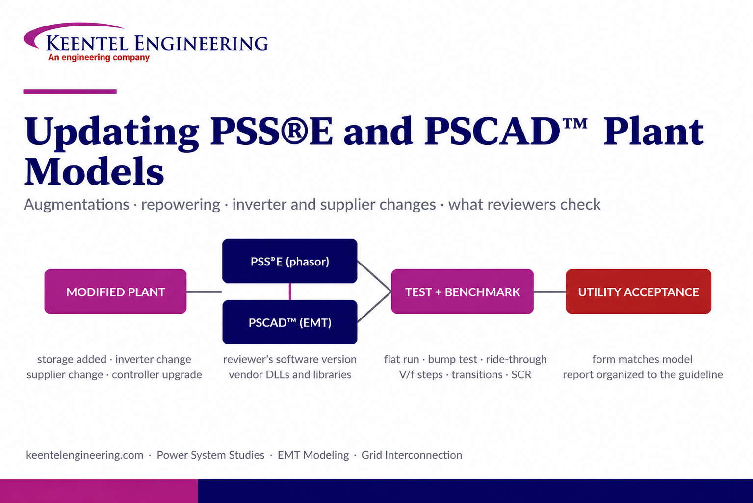
Learn how PSS®E and PSCAD™ model updates support plant augmentations, repowering, equipment changes, testing, benchmarking, and grid compliance.
By SANDIP R PATEL
•
September 20, 2026
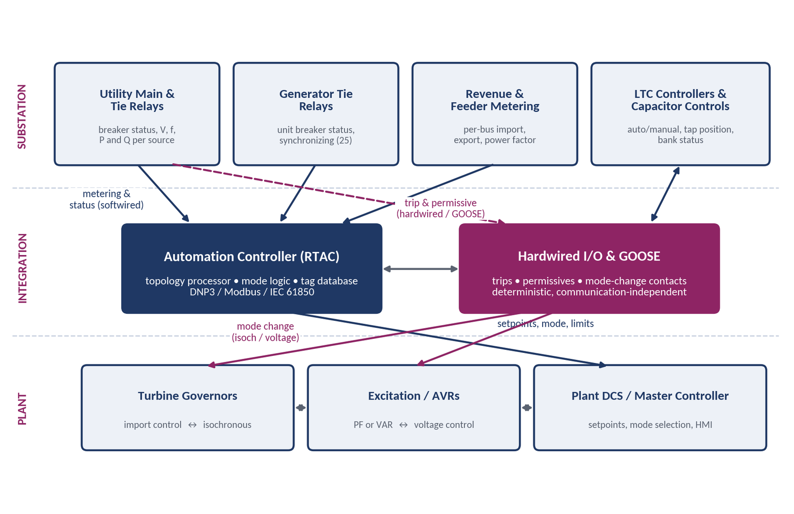
Learn CHP load following and island detection engineering for campus plants, including protection, controls, power studies, and grid transition design.
By SANDIP R PATEL
•
September 20, 2026
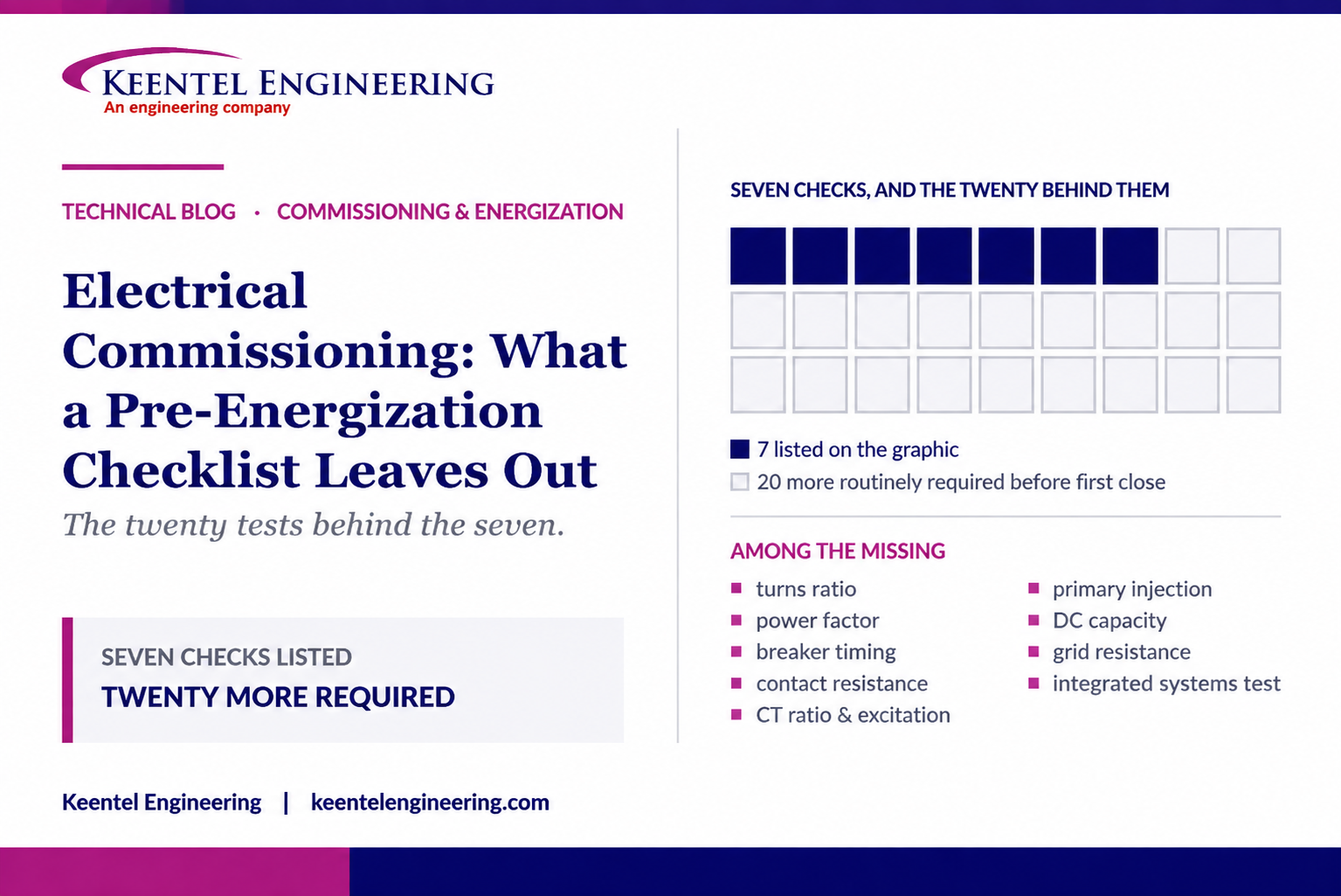
Learn what a pre-energization checklist misses, including electrical testing, protection checks, commissioning steps, and safe energization practices.
By SANDIP R PATEL
•
September 20, 2026
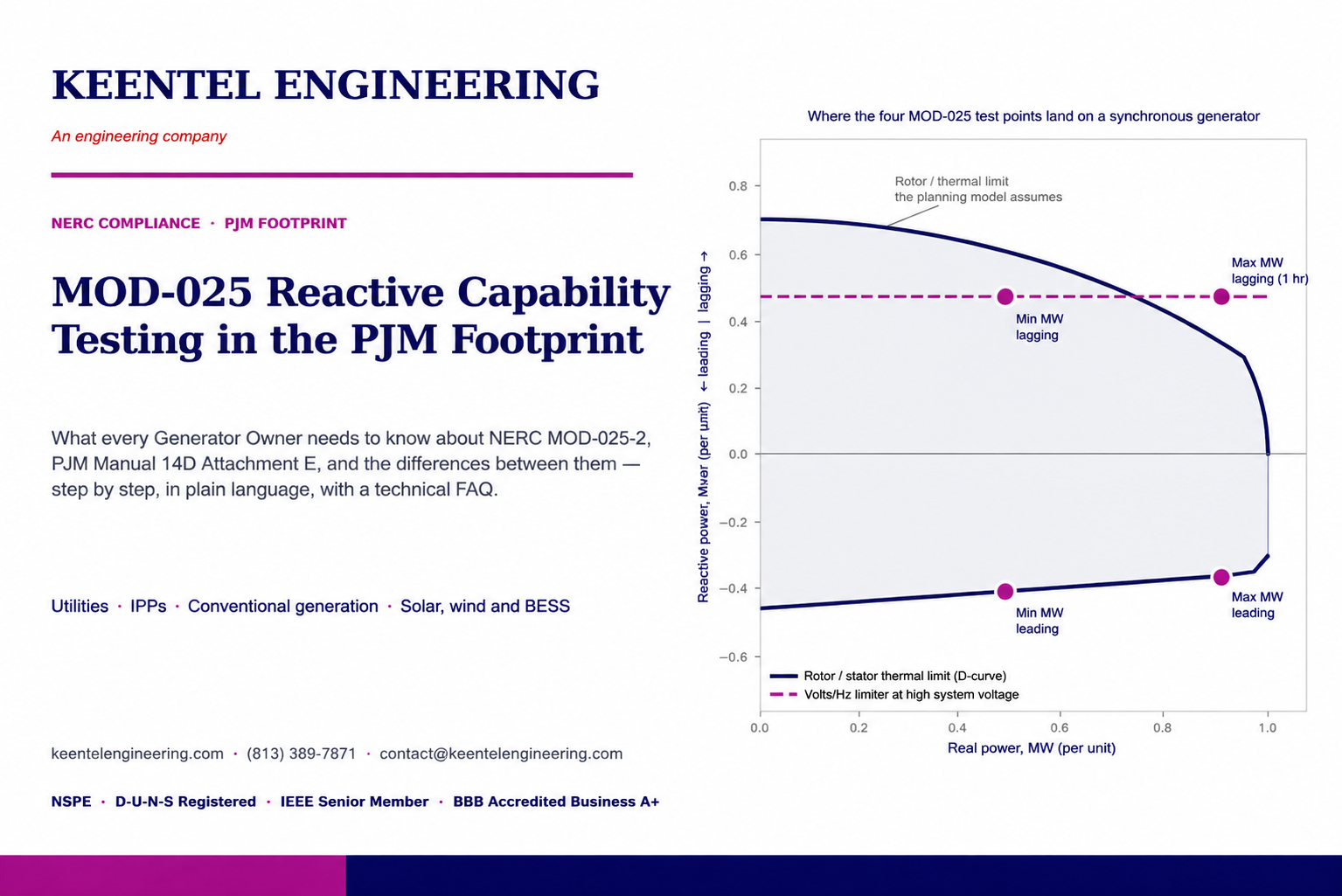
NERC MOD-025-2 Generator Owners, MOD-025-2 reactive power testing, generator capability verification, NERC Attachment 1, MOD-025 compliance testing
By SANDIP R PATEL
•
September 20, 2026
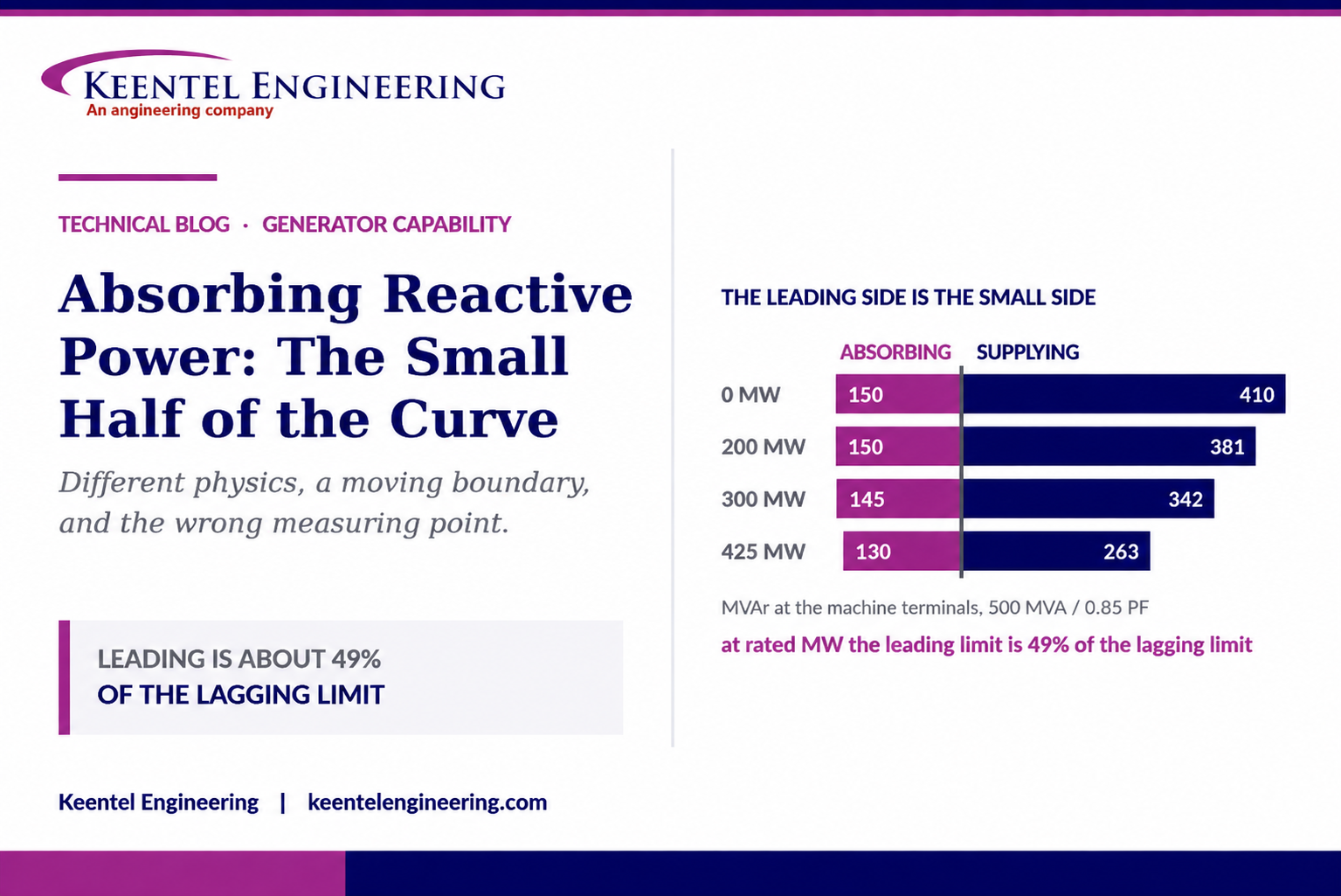
Understand generator capability curves, reactive power absorption, MVAr limits, MOD-025 verification, protection coordination, and grid requirements.
By SANDIP R PATEL
•
September 20, 2026
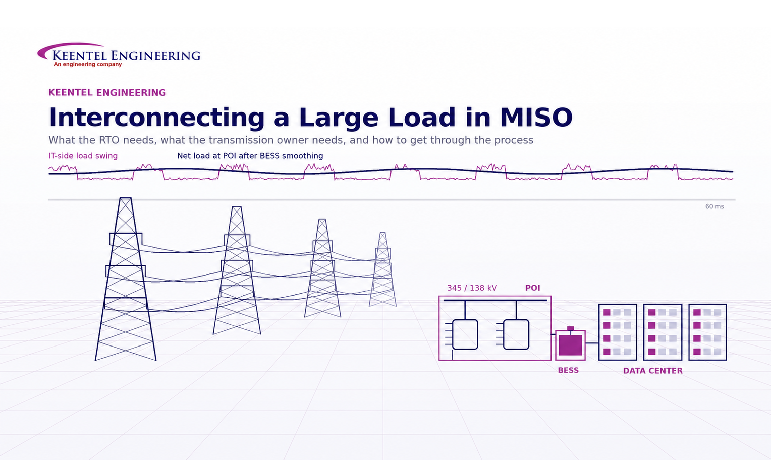
Understand MISO large load interconnection requirements for data centers, including TO data, PSS®E models, ride-through, harmonics, BESS and EPR.





