
A Coordinated Electric System Interconnection Review—the utility’s deep-dive on technical and cost impacts of your project.
Challenge: Frequent false tripping using conventional electromechanical relays
Solution: SEL-487E integration with multi-terminal differential protection and dynamic inrush restraint
Result: 90% reduction in false trips, saving over $250,000 in downtime
The three operating regions you have to design to
| Device | Output vs voltage | Response | Best suited to | Main limitations |
|---|---|---|---|---|
| Mechanically switched capacitor or reactor | Proportional to voltage squared | Seconds; discrete steps; limited switching operations per day | Steady-state reactive supply, voltage profile, loss reduction | No dynamic capability; step voltage change on switching; capability collapses when most needed |
| Static var compensator | Capacitive branches proportional to voltage squared | A few cycles; continuously controllable | Continuous control where cost matters and deep voltage support is not the driver | Square-law capability loss; harmonic filters are part of the plant and interact with the network |
| STATCOM | Approximately proportional to voltage — constant current capability | One to two cycles closed loop; converter response faster still | Voltage stability margin, weak interconnections, fast disturbance recovery, flicker and unbalance compensation | Higher capital cost; converter losses; adds a converter and its control dynamics to the network |
| Synchronous condenser | Governed by machine capability and excitation | Excitation response in the hundreds of milliseconds; inherent inertial response instantaneous | System strength and inertia, short-circuit contribution, black start support | Rotating plant with maintenance and losses; slower controlled response than a converter |
| STATCOM with energy storage | Reactive as a STATCOM, plus real power within the storage rating | As STATCOM for reactive; real power limited by storage | Where a real power deficiency is part of the problem | Cost and complexity of the storage; different failure and maintenance profile |
The Last Fifty Feet: Rack Power Distribution, Properly Sized
September 18, 2026 | Blog
PDU to RPP to Rack — Why a 60 Amp Rack PDU Deploys 40 Percent of Its Nameplate, What A/B Independence Actually Requires, and Where AI Densities Break the Conventional Architecture
1. Executive Summary
Rack power distribution is the last layer of the electrical system — the part between the critical distribution equipment and the servers themselves. It is also the layer where the reliability promised upstream is most often quietly lost, because the architecture looks simple and the arithmetic is not.
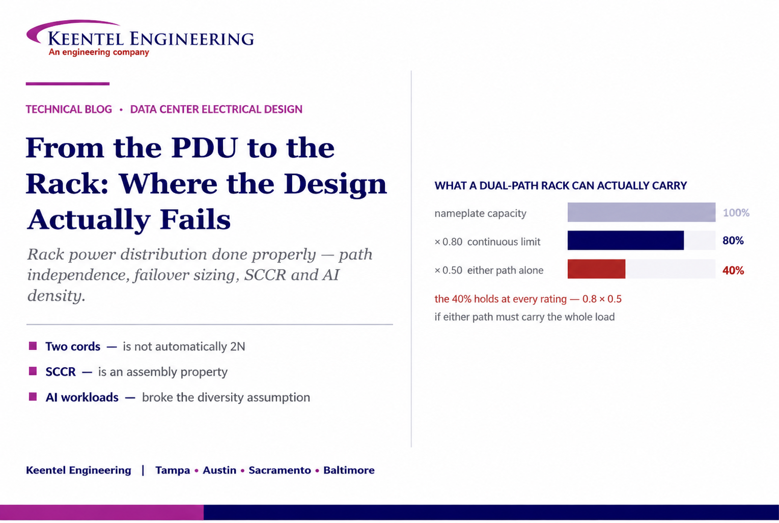
Three numbers make the point. A sixty ampere three-phase rack power distribution unit at 415 volts has a nameplate capacity of about forty-three kilovolt-amperes. Because data center load is continuous by definition, the usable continuous capacity is eighty percent of that — about thirty-four and a half. And if the design intent is that either supply path can carry the full load when the other is unavailable, the normal loading on each path cannot exceed half of that again. The deployable design load is about seventeen kilovolt-amperes per path: forty percent of the number printed on the label.
That cascade is the single most useful thing to understand about this layer, and it explains a great deal of what goes wrong. Capacity is planned against the nameplate, deployed against measured draw, and then discovered to be short at the first failover.
The second theme is independence. Two power cords do not make a dual-path installation. True independence has to run all the way back through the distribution, the uninterruptible supply, the switchboards, the transformers and the source — and through the cable routes and the physical spaces they pass through. Every element shared between the two paths is a common-mode failure waiting for the right fault.
The third is that the conventional architecture was designed for a load profile that artificial intelligence workloads have changed. Rack densities that were unusual at fifteen kilowatts are now routine at ten times that, diversity assumptions that held for mixed enterprise workloads do not hold for synchronised training jobs, and the distribution voltages, busway arrangements and cord counts are all moving as a result.
This paper works through the hierarchy, the sizing arithmetic, the independence question, fault current and coordination, harmonics, voltage drop, metering, and what changes at high density.
The sentence to take to a capacity meeting
The number on the rack power distribution unit is a nameplate. The deployable design load in a properly independent dual-path arrangement is roughly forty percent of it.
Planning capacity against the nameplate is how a hall runs out of power at sixty percent occupancy.
2. The Hierarchy, and What Each Level Actually Is
The conventional chain runs from the utility service through transformation, low-voltage switchgear and the uninterruptible power supply, into an output distribution switchboard, then down through three distribution levels to the equipment.
| Level | What it is | What it does | Typically |
|---|---|---|---|
| Floor PDU | Panelboard-level distribution unit on the data hall floor | Distribution breakers feeding multiple racks or multiple remote panels | May include an integral transformer — which changes its electrical character entirely, see Section 3 |
| RPP | Remote power panel — a panelboard placed closer to the load | Branch circuits feeding multiple racks, extending distribution without another transformer | Transformerless |
| Rack PDU | The strip or vertical unit inside the cabinet | Final distribution to the equipment outlets | Metering and monitoring, often per-outlet on newer units |
Three input arrangements are common at the distribution unit, and the graphic that prompted this paper sets them out correctly.
- Fed from the uninterruptible supply output. The straightforward case, and the one people assume.
- Fed from the uninterruptible supply with an alternate or bypass source through a transfer switch. This is where the second common design error lives: drawing the bypass as a normal parallel source rather than as an alternate with transfer and isolation logic. A bypass is a mode, not a second feed.
- Dual A and B arrangement with two complete distribution paths to two rack units, with no common feed and no shared path. This is the arrangement that supports genuine dual-corded equipment, and Section 7 is about what "no shared path" actually requires.
3. The Distinction the Transformer Creates
The most consequential difference between a floor distribution unit and a remote power panel is not size or position. It is whether there is a transformer inside.
A distribution unit with an integral transformer creates a separately derived system. That has specific and non-negotiable consequences.
- The neutral must be bonded to ground at exactly one point in that system, and that point is at or near the transformer. Not at the panel downstream, not again at the remote panel, not at the rack.
- The transformer’s impedance limits the fault current available downstream of it, which is why the available fault current at a remote panel fed from a transformer-equipped unit is far lower than at the switchboard upstream.
- It re-references the voltage, which is how a 480 volt distribution system becomes 415 or 208 volt utilisation power at the rack.
A transformerless remote power panel does none of these things. It is an extension of the system upstream of it. Its neutral is the upstream neutral, it has no bond of its own, and the fault current available at its bus is whatever the upstream transformer permits, less the impedance of the conductors in between.
The failure mode this produces is the one described in any grounding investigation: a second neutral-to-ground bond installed at a remote panel, because it looked like a service entrance. Normal neutral current then divides between the neutral conductor and every parallel path through the building steel and the grounding system, producing standing residual current on ground fault protection, potential differences between points of metalwork, interference on instrumentation, and accelerated corrosion. The diagnostic is straightforward: with the system loaded and healthy, a protective bonding conductor should carry essentially nothing.
The one-line check worth doing
On any distribution unit with an integral transformer, confirm the neutral-to-ground bond exists, is at one point, and is the only one in that separately derived system.
On any transformerless remote panel, confirm there is no bond at all. Both errors are common, both are invisible in normal operation, and both show up as a ground fault relay that will not stay set.
4. Sizing on Calculated Load, Not Rack Count
Sizing by rack count rather than by calculated load and fault level is listed as a common design error and it deserves unpacking, because the correct method is not obvious.
There are three different numbers for the power a server consumes, and confusing them is where the error starts.
| Quantity | What it is | How it is used |
|---|---|---|
| Nameplate rating | The power supply rating on the label — typically well above anything the device will draw, because it is sized for the worst case configuration of that chassis | Useful for conductor and overcurrent protection compliance in some contexts, and a poor basis for capacity planning. Commonly two to three times actual draw |
| Measured or benchmarked draw | What the equipment actually consumes running the intended workload, at the intended configuration | The right basis for capacity planning, and the reason branch circuit metering pays for itself |
| Design load | The value used for the electrical design, derived from measured draw with growth allowance, diversity and the continuous load factor applied | What the equipment is sized against |
The practical discipline is to design on a measured or vendor-benchmarked figure with an explicit allowance, state the assumption in the design basis, and then instrument the installation so the assumption can be checked against reality. A design that says "assume ten kilowatts per rack" without saying where the ten came from cannot be defended when the racks arrive drawing fourteen.
5. The Continuous Load Factor
Data center load runs continuously. That is not a figure of speech — it is a defined condition in the electrical code, where a continuous load is one expected to persist for three hours or more, and it carries a specific requirement.
Branch circuit overcurrent devices and conductors serving a continuous load must be sized at not less than one hundred and twenty-five percent of that load. The practical inversion is the one people actually use: a device may carry no more than eighty percent of its rating as continuous load.
So a sixty ampere rack distribution unit carries forty-eight amperes of continuous load. A one hundred ampere branch device carries eighty. This is well understood in principle and routinely lost in capacity planning, where the nameplate figure is the one that ends up in the spreadsheet.
Note that some rack distribution units and branch circuit devices are listed for one hundred percent continuous duty, and where that listing exists the derating does not apply. It has to be verified on the specific product rather than assumed, and it is the exception.
6. Diversity, and What AI Workloads Did to It
Diversity is the recognition that not everything draws its maximum at the same instant. Applied realistically it is sound engineering; applied optimistically it is how a hall ends up with insufficient upstream capacity.
The conventional picture had diversity increasing as you move up the hierarchy. At the rack, coincidence is high because the servers in a cabinet tend to do similar work. At the distribution unit, mixed workloads across racks give some diversity. At the facility level, more still.
Artificial intelligence training has weakened that picture considerably, and it is worth being explicit about why. A large training job runs synchronously across many accelerators, often across many racks and sometimes across an entire hall. They step together, they compute together, and they pause together at synchronisation boundaries. The result is a load that is far more coincident than a mixed enterprise environment and that also swings in a coordinated way — which is a power quality and a ramping problem as well as a capacity one.
Three consequences for the rack power design.
- Diversity factors carried over from enterprise design are not transferable to a training hall. Assume coincidence close to unity across racks in the same job, and justify anything lower.
- The coordinated swing matters upstream. Coincident load steps of that magnitude are visible at the point of interconnection and are part of why large computational loads have become a grid reliability topic in their own right.
- Power capping and workload-level power management become design inputs rather than operational conveniences. If the design relies on the load being limited, the mechanism that limits it is part of the electrical design and has to be treated accordingly.
7. A/B Independence: What Separate Has to Mean
Two power cords are not automatically a dual-path installation. This is the most important statement in the source material and it is worth extending, because the list of things that must be separate is longer than most designs check.
| Element | What independence requires | Where it is commonly shared by accident |
|---|---|---|
| Source | Separate utility service or separate generation, where the design calls for it | Two feeders from the same substation bus, or two services that meet at the same utility transformer |
| Transformer | Separate transformers | A single transformer with two secondary breakers described as two paths |
| Switchboard | Separate low-voltage switchboards | Two sections of one switchboard with a tie — which is not two switchboards |
| UPS | Separate uninterruptible supply systems | A shared static switch, a shared battery system, or a shared bypass source |
| Distribution | Separate distribution units and remote panels | A single distribution unit feeding both A and B rack units |
| Cable route | Physically separate routes | Both paths through the same tray, the same shaft, the same underfloor route or the same wall penetration |
| Control and monitoring | Separate control power and network paths | One building management network, one control power source, one time reference |
| Room and compartment | Physical separation where the design intent is fault tolerance | Both paths in the same electrical room, which survives no fire and no flood |
The instrument that finds these is a cross-discipline review with the single line diagram, the cable routing drawings, the control architecture and the physical layout on the table at the same time. Each discipline reviewing its own drawings will confirm its own redundancy and miss every dependency that crosses a boundary — which is where all of them are.
It is also worth being precise about what level of redundancy is intended. Two independent paths that each carry the full load is a different thing from two paths that share the load and each carry half, from a distributed redundant arrangement with a catcher, and from concurrent maintainability without fault tolerance. The design basis should say which, in those terms, because "A and B" describes a topology rather than a capability.
8. The Failover Sizing Trap
This follows directly and it is where the arithmetic in the executive summary comes from.
If the design intent is that either path can carry the whole load when the other is unavailable, then in normal operation each path must be loaded at no more than half of what it can carry continuously. Otherwise the failover that the architecture exists to survive is the event that trips it.
| Step | Sixty ampere unit at 415/240 V three-phase | One hundred ampere unit at 415/240 V three-phase |
|---|---|---|
| Nameplate capacity | About 43.1 kVA | About 71.9 kVA |
| Continuous limit at eighty percent | About 34.5 kVA | About 57.5 kVA |
| Per-path design load if either path must carry all of it | About 17.3 kVA | About 28.8 kVA |
| Deployable load as a share of nameplate | About forty percent | About forty percent |
The forty percent result is independent of the rating, which is what makes it a useful rule. It also has to be applied consistently up the chain: the branch circuit, the remote panel breaker, the distribution unit, its transformer and the upstream switchboard all need the same treatment, because a failover loads all of them.
Where an owner deliberately accepts higher normal loading — running each path harder and accepting that a failover sheds or caps load — that is a legitimate decision. It is a decision, it belongs in the design basis, and the mechanism that does the shedding or capping has to exist and be tested. What is not legitimate is designing to eighty percent per path, calling it two N, and discovering the difference during an event.
9. Single-Corded Loads and the Transfer Switch
Dual-path distribution assumes dual-corded equipment. A meaningful fraction of what goes in a rack is not: some network switches, out-of-band management appliances, older storage controllers, and almost anything from outside the mainstream server vendors.
The conventional answer is a rack-level automatic or static transfer switch taking both feeds and presenting one output. It works, and it introduces something the dual-path architecture was specifically designed to avoid.
- The transfer switch is a single point of failure for everything downstream of it. Two paths in, one device, one output.
- It is a deliberate common-mode coupling between A and B, in a design whose entire premise is that they never touch.
- Transfer is not instantaneous. A static device transfers in a fraction of a cycle and an electromechanical one takes longer; whether the load rides through depends on the equipment’s own tolerance.
- Its capacity and its own supply arrangement have to be designed with the same failover logic as everything else.
The engineering response is to be deliberate rather than to avoid it. Inventory the single-corded equipment early rather than discovering it at installation. Where the load is critical, consider whether a redundant pair of devices on opposite paths is better than one device on a transfer switch. Where a transfer switch is used, specify its transfer characteristics against the tolerance of what it feeds, and treat it as a component with a failure rate rather than as a piece of wiring.
10. Fault Current, SCCR, and the Assembly Rating
Two ratings are involved and they are not the same, which is a distinction that causes trouble in every part of electrical engineering and is particularly easy to miss at this level.
- The interrupting rating of a protective device is what that device can interrupt. It is marked on the breaker or fuse.
- The short-circuit current rating of an assembly — a distribution unit, a remote panel, a rack unit — is what the whole enclosure can withstand while a protective device clears the fault. It is marked on the assembly nameplate, and it is limited by the weakest component in the power circuit, which is frequently not a breaker at all. A control transformer, a terminal block, a surge device or a relay can cap the rating of an otherwise robust assembly.
Both have to be verified against the available fault current at the point of installation. That current comes from an engineering calculation, not an assumption, and at this level the dominant limiting element is usually the impedance of the nearest upstream transformer — which is exactly why ignoring transformer impedance is on the common error list.
The relationship is worth stating plainly, because it cuts both ways. A low-impedance transformer gives better voltage regulation and higher available fault current. A high-impedance one does the reverse. Choosing the transformer changes what the downstream equipment must be rated for, and a transformer substitution made for delivery reasons can invalidate the ratings of everything behind it.
11. Selective Coordination Against Arc Flash
Selective coordination means that for a fault anywhere in the system, only the protective device immediately upstream of the fault operates. Achieving it across four levels of distribution is genuinely difficult, and it sits in direct tension with another objective.
The difficulty is at the fast end. Coordination between a small branch device and a larger upstream one is straightforward in the overload region and becomes hard in the instantaneous region, where the characteristics of the two devices overlap and both may operate for the same high-current fault. The conventional tools are current-limiting devices, deliberate time-current separation, and zone selective interlocking, in which a downstream device signals upstream that it has seen the fault so the upstream device waits.
The tension is with incident energy. Arc flash energy is roughly proportional to clearing time, so everything that improves coordination by slowing the upstream device increases the energy released if a fault occurs at that upstream location. Zone selective interlocking is valuable precisely because it resolves some of that conflict — it allows the upstream device to be fast when the fault is in its own zone and patient when it is not.
Three practical points for this layer.
- Decide whether selective coordination is a requirement or an aspiration, and record which. It is a code requirement for certain occupancies and a specified owner requirement in many data centers; the design effort differs enormously between the two.
- Arc flash study and labelling must reflect the settings actually installed. A coordination study issued at design and settings adjusted during commissioning without re-running the incident energy calculation leaves labels that are wrong.
- Energy-reducing maintenance switching — a mode that trades coordination for speed while someone is working on the equipment — is the standard answer where the conflict cannot be resolved, and it needs to be specified rather than assumed.
12. Harmonics and the Neutral
Harmonic loading and heating appears on the engineering check list and the modern picture is more nuanced than the traditional treatment.
The classical concern was triplen harmonics from single-phase switch-mode power supplies without power factor correction. Those are zero-sequence quantities, so they add arithmetically in the shared neutral of a three-phase four-wire circuit rather than cancelling, and a neutral carrying more current than the phases is a genuine fire risk. The traditional responses were oversized neutrals and specially rated transformers.
Modern server power supplies almost universally include active power factor correction, and their harmonic content at reasonable load is low. That has changed the calculus in two ways that matter.
- Neutral oversizing and specially rated transformers are frequently over-specified in modern halls, and specifying them reflexively adds cost without benefit. The question is what is actually connected.
- Corrected supplies behave worst at light load, so a lightly loaded hall can show worse distortion than a fully loaded one. Measuring at partial occupancy and extrapolating gives a pessimistic answer; measuring at full load and extrapolating downward gives an optimistic one.
The other change is where the harmonics now come from. On a modern campus the dominant sources are frequently not the servers but the mechanical plant — a large population of variable frequency drives on pumps, fans and chillers — together with the uninterruptible supply rectifiers and lighting drivers. Assessing distortion at the rack level and concluding the facility is clean misses most of the problem, and compliance is in any case assessed at the point of common coupling rather than inside the building.
13. Voltage Drop as a Budget
Voltage drop is listed at three levels — distribution unit, remote panel and rack — and the reason it is listed three times is that it accumulates.
The code treats voltage drop as a recommendation rather than a requirement, with the familiar guidance of about three percent on a branch circuit and about five percent overall from service to outlet. The practical discipline is to treat that as a budget and allocate it explicitly across the levels, rather than checking each segment independently and discovering the total only at the outlet.
Two design levers change the arithmetic materially.
- Distribution voltage. At 415 volts three-phase with 240 volt line-to-neutral utilisation, the current for a given kilowatt is substantially lower than at 208 volts with 120 volt utilisation. Lower current means lower drop in the same conductor and lower losses, which is one of the principal reasons high-density halls moved to the higher voltage.
- The remote power panel itself. Placing a panel closer to the racks shortens the branch circuits, which is exactly what it exists for. A remote panel placed for room-planning convenience rather than electrical distance gives up that benefit.
Losses follow the same relationship as drop and they are continuous. A percent of loss in the rack distribution layer is a percent of the information technology load, every hour, for the life of the facility — which is worth putting into the same economic comparison used for any other conductor sizing decision.
14. Metering and Stranded Capacity
Metering and monitoring is on the engineering check list and it is usually justified on the wrong grounds. It is not primarily about visibility; it is about capacity.
Without measurement, capacity is planned against nameplate. Nameplate is conservative by a large factor, so the hall is planned as full while the equipment draws a fraction of what was reserved for it. Capacity that has been allocated but is not being used is stranded — paid for in transformers, switchgear, uninterruptible supply and cooling, and generating nothing.
Branch circuit monitoring at the distribution unit and metering at the rack unit turn that reserved figure into a measured one, which allows the difference to be released. On a large hall the recovered capacity is a material number, and it is recovered without installing anything upstream.
Three levels of measurement are worth distinguishing when specifying.
- Inlet metering on the rack unit — the minimum, giving the total per cabinet per path.
- Branch or bank metering within the rack unit — enough to see phase balance within the cabinet, which is where neutral loading and single-phase imbalance problems appear.
- Per-outlet metering — the most granular, and the level at which individual equipment behaviour and chargeback become possible. It costs more and it is not always needed; the honest question is what decision the data will inform.
Whatever level is chosen, the measurement is only as good as its integration. Data that lands in a system nobody uses for capacity decisions has not recovered anything.
15. Where AI Densities Change the Architecture
The architecture in the source material is correct and it was drawn for a load profile that is no longer the only one. High-density artificial intelligence deployment changes several things at this layer.
- Rack density. Cabinets that were considered dense at ten to fifteen kilowatts are being deployed at many times that, and the direction of travel is upward. At those levels the branch circuit, the rack unit, the cord and the connector all have to be reconsidered rather than scaled.
- Distribution voltage. Higher utilisation voltage reduces current for the same power, which reduces conductor size, voltage drop and losses. The move to 415 volts three-phase with 240 volt line-to-neutral is largely driven by density.
- Busway instead of branch circuits. Overhead busway with tap-off boxes replaces individually run branch circuits, which changes the flexibility model — capacity is added by moving a tap rather than by pulling a circuit — and changes the protection and metering arrangement with it.
- Cord count. A dual-corded assumption does not survive a rack drawing over a hundred kilowatts. Multiple supply connections per cabinet change what independence means and complicate the A and B allocation within the cabinet.
- Direct current distribution. Higher-voltage direct current architectures are being developed and deployed to avoid repeated conversion stages at high density. They are a genuine departure from the arrangement described here, with their own protection, isolation and fault-detection engineering, and a design team should not assume the alternating current practice transfers.
- Coincidence, as discussed in Section 6, which removes much of the diversity the conventional design relied on.
The practical guidance is to establish which kind of hall is being designed before applying any rule of thumb from this layer. A conventional enterprise hall and a training hall are different electrical problems that happen to share a vocabulary.
16. Commissioning What You Designed
The commissioning list in the source material is sound. What is worth adding is the structure around it and the two tests that are most often skipped.
Commissioning progresses from factory testing, through component verification and subsystem function, to integrated systems testing where the whole installation is exercised as one. Everything discussed in this paper is a system-level property — path independence, failover capacity, coordination, harmonic behaviour under load — and every one of them will pass a component test.
The two that matter most and are most often compromised:
- The A and B path test at representative load. Not a continuity check and not a de-energised verification — an actual transfer, at load, with the surviving path measured against its continuous rating. This is the test that finds the failover sizing trap in Section 8, and it finds it before the equipment is in service rather than during an event.
- The thermal scan under representative load. A scan at ten percent occupancy finds nothing, because a loose termination at ten percent load is not yet hot. Achieving representative load before the equipment arrives requires load banks, and load bank hire is the line item most often cut from a commissioning budget.
Two smaller items that repay the effort: torque verification recorded rather than performed, since an unrecorded torque check is indistinguishable from no check; and as-built labelling verified against the drawings, because the first person to troubleshoot this installation at three in the morning will be relying on it.
17. Reading the Chart Correctly
The architecture is right
The hierarchy from source through transformation, low-voltage switchgear and uninterruptible supply into distribution unit, remote panel and rack unit is correct, and the three input arrangements are correctly distinguished. So is the point that a bypass is an alternate source requiring transfer and isolation logic rather than a parallel feed.
The independence warning is the most important line
Two power cords are not automatically a dual-path installation. Section 7 extends the list of what has to be separate, and the additions that matter most are control power, the monitoring network, physical cable routes and the rooms the equipment sits in.
The transformer is the real distinction between a PDU and an RPP
The chart notes that a floor distribution unit may include a transformer and that a remote panel typically does not. The consequence is the part worth knowing: an integral transformer creates a separately derived system requiring exactly one neutral-to-ground bond, and limits the fault current available downstream.
Calculated load needs a stated method
Sizing by calculated load rather than rack count is correct advice and it is incomplete without saying which load. Nameplate, measured draw and design load are three different numbers, and the continuous load factor applies on top of whichever is used.
The forty percent result is not on the chart
Continuous derating and failover capability compound. In a dual-path arrangement where either path must carry the whole load, the deployable design load is about forty percent of the rack unit nameplate. That single figure explains most capacity planning surprises at this layer.
Single-corded equipment is missing
Every dual-path design contains some, the usual answer is a rack transfer switch, and that switch is a single point of failure and a deliberate coupling between A and B. It should be inventoried at design rather than discovered at installation.
High-density changes the picture
The architecture as drawn was designed for a load profile that artificial intelligence deployment has changed — in density, in coincidence, in distribution voltage, in busway versus branch circuits, in cord count, and increasingly in direct current architectures. It remains correct for conventional halls.
18. Keentel Data Center Electrical Services
Keentel Engineering provides the electrical engineering behind data center campuses — from the point of interconnection through the distribution architecture to the rack, and through commissioning.
18.1 Distribution Design and Studies
- Critical power distribution design from the service through switchgear, uninterruptible supply, distribution units, remote panels and rack distribution, with the redundancy intent stated in design-basis terms rather than as a topology label.
- Load calculation and capacity planning on a documented basis, with the continuous load factor, diversity assumptions and failover capability applied consistently up the chain.
- Short-circuit, protective coordination and arc-flash studies, including assembly short-circuit current rating verification and the coordination-versus-incident-energy trade resolved explicitly.
- Load flow, voltage drop budgeting, harmonic and power quality studies, including the mechanical plant drive population and compliance assessed at the correct point.
- Grounding and bonding design, separately derived system identification and single-point bonding verification.
18.2 Redundancy and Resilience Assurance
- Cross-discipline failure mode and effects analysis across electrical, mechanical and controls, including physical routing review — the only method that reliably finds common-mode dependencies.
- A and B path independence audit against the full element list, including control power, monitoring networks, cable routes and physical compartmentation.
- Failover capacity verification at every level of the distribution chain, and evaluation of load shedding or capping mechanisms where higher normal loading is deliberately accepted.
- Single-corded equipment inventory and transfer switch application review.
18.3 Interconnection and Campus Power
- Large load interconnection engineering, application support and study-phase technical packages, and coordination with the utility, transmission provider and system operator.
- Point-of-interconnection and substation design, campus medium-voltage distribution, and on-site generation and storage integration.
- Facility ride-through capability assessment and transfer scheme review against the site disturbance environment.
- Registration applicability assessment and compliance programme support where the facility falls within the reliability framework.
18.4 Commissioning and Owner’s Engineer
- Commissioning specification and integrated systems test procedure development, including the A and B path test at representative load and thermal scanning with load banks.
- Witness and verification support, acceptance criteria written to be measurable, and trending architecture design.
- Design review of engineering and vendor packages, QA/QC of third-party studies, and technical specification development.
- Performance investigation where a facility has experienced an outage, a failover that did not hold, or capacity that cannot be deployed.
Keentel Engineering holds a Florida Certificate of Authorization and maintains offices in Tampa, Austin, Sacramento, and Baltimore, supporting projects across the interconnections.
19. Frequently Asked Questions
Q1. What is rack power distribution?
The final distribution layer between the critical distribution equipment and the information technology hardware — typically a floor distribution unit, a remote power panel, and the rack unit inside the cabinet. It preserves power quality, protection, maintainability and path independence all the way to the equipment.
Q2. What is the difference between a floor PDU and a remote power panel?
Principally the transformer. A floor distribution unit may include an integral transformer; a remote power panel typically does not. That single difference determines whether the equipment creates a separately derived system, and therefore how it must be grounded and what fault current is available downstream.
Q3. Why does the transformer matter so much?
Because a transformer creates a separately derived system. Its neutral must be bonded to ground at exactly one point, at or near the transformer; its impedance limits the fault current available downstream; and it re-references the utilisation voltage. A transformerless panel does none of these — it is an extension of the system upstream of it and must have no bond of its own.
Q4. What happens if a transformerless panel is bonded anyway?
Normal neutral current divides between the neutral conductor and every parallel path through building steel and the grounding system. The symptoms are standing residual current that causes nuisance ground fault operation, potential differences between metalwork, interference on instrumentation, and accelerated corrosion. With the system loaded and healthy, a protective bonding conductor should carry essentially nothing.
Q5. What does sizing by calculated load rather than rack count mean?
That you cannot multiply cabinets by an assumed kilowatt figure. There are three different numbers — nameplate rating, measured or benchmarked draw, and design load — and they differ substantially. Nameplate is commonly two to three times actual draw. Design on measured or vendor-benchmarked figures with a stated allowance, and instrument the installation so the assumption can be checked.
Q6. What is the continuous load factor?
Data center load runs continuously, which in code terms means three hours or more. Conductors and overcurrent devices serving a continuous load must be sized at not less than one hundred and twenty-five percent of it — the practical inversion being that a device carries no more than eighty percent of its rating. A sixty ampere unit carries forty-eight amperes continuously.
Q7. Are there exceptions?
Some devices and assemblies are listed for one hundred percent continuous duty, and where that listing exists the derating does not apply. It must be verified on the specific product rather than assumed, and it is the exception rather than the rule.
Q8. Where does the forty percent figure come from?
Two factors compounding. Eighty percent for continuous duty, then half again if either supply path must carry the entire load when the other is unavailable. A sixty ampere three-phase unit at 415 volts has about 43.1 kVA of nameplate capacity, about 34.5 kVA continuous, and about 17.3 kVA of deployable load per path — roughly forty percent of the label.
Q9. Does that result depend on the rating?
No, which is what makes it useful. The same forty percent applies to a one hundred ampere unit. It also has to be applied consistently up the chain — branch circuit, panel breaker, distribution unit, transformer and upstream switchboard — because a failover loads all of them.
Q10. Can we run each path harder than fifty percent?
Yes, as a deliberate decision. If the design accepts that a failover will shed or cap load rather than carry it, that is legitimate — provided it is stated in the design basis and the shedding or capping mechanism actually exists and has been tested. What is not legitimate is loading to eighty percent per path, describing it as dual redundant, and finding out during an event.
Q11. Are two power cords enough for a dual-path installation?
No, and this is the most important single point. Independence has to run back through the distribution units, the uninterruptible supply systems, the switchboards, the transformers and the source — and through the cable routes, the control power, the monitoring network and the physical rooms. Anything shared is a common-mode failure waiting for the right fault.
Q12. What gets shared by accident most often?
Cable routes through a common tray, shaft or wall penetration; control power and the building management network; two sections of a single switchboard described as two switchboards; a shared bypass source or static switch on the uninterruptible supply; and both paths terminating in the same electrical room.
Q13. How do you find those dependencies?
A cross-discipline review with the single line diagram, cable routing drawings, control architecture and physical layout on the table simultaneously. Each discipline reviewing its own drawings confirms its own redundancy and misses every dependency that crosses a boundary — which is where all of them are.
Q14. What about equipment with only one power cord?
Every dual-path installation has some — network switches, management appliances, older storage. The usual answer is a rack-level transfer switch taking both feeds and presenting one output, which works and introduces a single point of failure and a deliberate coupling between A and B in a design premised on their never touching.
Q15. How should transfer switches be handled?
Deliberately. Inventory single-corded equipment at design rather than at installation; consider whether a redundant pair of devices on opposite paths beats one device on a transfer switch where the load is critical; specify transfer characteristics against the tolerance of what is fed; and treat the switch as a component with a failure rate rather than as wiring.
Q16. What is the difference between interrupting rating and SCCR?
Interrupting rating is what a single protective device can interrupt, marked on the breaker or fuse. Short-circuit current rating is what a whole assembly can withstand while a device clears, marked on the assembly nameplate, and capped by the weakest component in the power circuit — often a control transformer, terminal block or relay rather than a breaker. Both must be verified against the calculated available fault current.
Q17. Why does transformer impedance matter at this level?
Because it is usually the dominant element limiting available fault current downstream. A low-impedance transformer gives better voltage regulation and higher fault current; a high-impedance one the reverse. Substituting a transformer for delivery reasons can invalidate the ratings of everything behind it.
Q18. Why is selective coordination difficult here?
Because it is hard at the fast end. Coordination in the overload region is straightforward; in the instantaneous region the characteristics of a small branch device and a larger upstream device overlap and both may operate. The tools are current-limiting devices, deliberate time separation, and zone selective interlocking.
Q19. How does coordination conflict with arc flash?
Incident energy scales roughly with clearing time, so slowing an upstream device to achieve coordination increases the energy released by a fault at that device. Zone selective interlocking helps because it lets the upstream device be fast for faults in its own zone and patient otherwise. Energy-reducing maintenance switching is the standard answer where the conflict cannot be resolved.
Q20. Do we still need oversized neutrals and K-rated transformers?
Often not, and specifying them reflexively adds cost without benefit. Modern server power supplies almost universally include active power factor correction and produce low harmonic content at reasonable load. The question is what is actually connected — and note that corrected supplies behave worst at light load, so measurement at partial occupancy gives a pessimistic answer.
Q21. Where do the harmonics actually come from on a modern campus?
Frequently not the servers. The dominant sources tend to be the mechanical plant — a large population of variable frequency drives on pumps, fans and chillers — together with uninterruptible supply rectifiers and lighting drivers. Assessing distortion at the rack and concluding the facility is clean misses most of it, and compliance is assessed at the point of common coupling in any case.
Q22. How should voltage drop be handled across four levels?
As an allocated budget rather than four independent checks. The familiar guidance is about three percent on a branch circuit and five percent overall. Higher distribution voltage reduces current for the same power and therefore drop and losses, which is a principal reason high-density halls moved to 415 volts three-phase with 240 volt utilisation.
Q23. What is metering actually for?
Capacity, more than visibility. Without measurement, capacity is planned against nameplate, which is conservative by a large factor, so the hall is planned as full while equipment draws a fraction of what was reserved. Branch and rack metering turn a reserved figure into a measured one and release the difference — recovering capacity without installing anything upstream.
Q24. What changes at AI rack densities?
Almost everything at this layer. Density well beyond conventional levels; higher distribution voltage; busway with tap-offs replacing individually run branch circuits; more than two supply connections per cabinet, which complicates what independence means inside the rack; emerging higher-voltage direct current architectures with their own protection engineering; and coincidence close to unity, which removes the diversity the conventional design relied on.
Q25. Which commissioning tests are most often skipped and most worth keeping?
The A and B path test at representative load — an actual transfer, at load, with the surviving path measured against its continuous rating, which is what finds the failover sizing problem before service. And the thermal scan at representative load, which requires load banks, because a loose termination at ten percent occupancy is not yet hot enough to find.
References and Further Reading
The following are referenced by subject in the body of this document. The edition adopted by the authority having jurisdiction governs code requirements, and the current published edition of each standard governs its own content.
Code and Safety
- NFPA 70, National Electrical Code — including the articles covering branch circuits and continuous loads, overcurrent protection, grounding and bonding and separately derived systems, and arc energy reduction requirements — National Fire Protection Association
- NFPA 70E, Standard for Electrical Safety in the Workplace, and IEEE Std 1584, Guide for Performing Arc-Flash Hazard Calculations — National Fire Protection Association and IEEE Standards Association
- UL 60950 and UL 62368 series for information technology equipment, UL 67 for panelboards, UL 891 and UL 1558 for switchboards and switchgear, and the applicable listing standards for power distribution units and rack distribution equipment — UL Standards & Engagement
Power Quality, Grounding, and Studies
- IEEE Std 1100, Recommended Practice for Powering and Grounding Electronic Equipment — the Emerald Book — IEEE Standards Association
- IEEE Std 142, Recommended Practice for Grounding of Industrial and Commercial Power Systems, and IEEE Std 3003 series on grounding and power system analysis — IEEE Standards Association
IEEE Std 519 for harmonic control, IEEE Std 1159 for power quality monitoring, and IEEE Std 3002.8 for harmonic studies — IEEE Standards Association- IEEE Std 3002.3 for short-circuit studies, the IEEE 3004 series for protection and coordination, and the IEEE 3006 series for reliability analysis — IEEE Standards Association
Data Center Design and Commissioning
ANSI/TIA-942, Telecommunications Infrastructure Standard for Data Centers, and ANSI/BICSI 002, Data Center Design and Implementation Best Practices — TIA and BICSI
Uptime Institute Tier Standard: Topology and Tier Standard: Operational Sustainability, covering concurrent maintainability and fault tolerance — Uptime Institute
ASHRAE Standard 90.4, Energy Standard for Data Centers, and the ASHRAE Datacom series including the thermal guidelines — ASHRAE
- Open Compute Project rack and power specifications, including high-density rack power and direct current distribution work —
Open Compute Project
Notice and Disclaimer
This document is original technical content prepared by Keentel Engineering LLC for general professional information. It is not legal, regulatory, or project-specific engineering advice, and it does not constitute a registration determination, an applicability determination, a compliance determination, or a design for any facility.
Facts about events, dates, standards, thresholds and programme status are taken from the three NERC publications identified in the References section, as published. This programme is moving quickly under a regulatory deadline: registry criteria, standard content, comment periods and effective dates are subject to change, and several matters described here were expressly stated by NERC as not yet final. Verify the current position with NERC, the applicable Regional Entity and the interconnecting utility before making any decision.
Analysis, inference, engineering commentary and the recommended actions in this document are Keentel Engineering’s own assessment and should not be attributed to NERC, any Regional Entity, any regulator, or any party named or referenced.
Descriptions of facility protection and transfer scheme behaviour are general engineering discussion; any change to a protection or control scheme must be made by qualified persons with the equipment manufacturer and against the actual tolerance of the equipment being protected.
Keentel Engineering LLC is an independent engineering consultancy. Reference to any regulator, reliability organisation, regional entity, standard, industry organisation, utility, or facility in this document does not imply affiliation with, endorsement by, or sponsorship from any such organisation.

About the Author:
Sandip "Sonny" R. Patel, P.E.
IEEE Senior Member · Founder & CEO, Keentel Engineering
In 1995, Sonny Patel earned his Electrical Engineering degree from the University of Illinois. But degrees don't build legacies — action does.
For three decades, he has worked the power industry from every side of the table: 16 years as a utility engineer at Exelon/Commonwealth Edison; generation leadership across hydroelectric, industrial steam turbine, and a 9 GW renewable fleet; NERC Regional Entity Senior Compliance Engineer and Audit Team Lead, auditing some of the nation's largest utilities; and testing and commissioning lead on equipment up to 765 kV — the very top of the North American grid.Utility. Generator. Regulator. Consultant. Few engineers have seen all four seats. Fewer still have sat in them.
His experience spans nuclear, hydro, conventional generation, renewables, oil and gas, mining — and today's data centers, where he is authoring a three-book series on data center design. He is a Licensed Professional Engineer in six states and a Licensed Electrical Contractor in Florida (Unlimited EC) — he doesn't just design the work; he's qualified to stand behind its execution.Today, as Founder and CEO of Keentel Engineering, Sonny leads a nationwide team of engineers delivering substation design, power system studies, NERC compliance, and commissioning — done right, coast to coast.Three decades. Every side of the table. One standard: accountable engineering.
Services

Let's Discuss Your Project
Let's book a call to discuss your electrical engineering project that we can help you with.
About the Author:
Sandip "Sonny" R. Patel, P.E.
IEEE Senior Member · Founder & CEO, Keentel Engineering
In 1995, Sonny Patel earned his Electrical Engineering degree from the University of Illinois. But degrees don't build legacies — action does.
For three decades, he has worked the power industry from every side of the table: 16 years as a utility engineer at Exelon/Commonwealth Edison; generation leadership across hydroelectric, industrial steam turbine, and a 9 GW renewable fleet; NERC Regional Entity Senior Compliance Engineer and Audit Team Lead, auditing some of the nation's largest utilities; and testing and commissioning lead on equipment up to 765 kV — the very top of the North American grid.
Utility. Generator. Regulator. Consultant. Few engineers have seen all four seats. Fewer still have sat in them.
His experience spans nuclear, hydro, conventional generation, renewables, oil and gas, mining — and today's data centers, where he is authoring a three-book series on data center design. He is a Licensed Professional Engineer in six states and a Licensed Electrical Contractor in Florida (Unlimited EC) — he doesn't just design the work; he's qualified to stand behind its execution.
Today, as Founder and CEO of Keentel Engineering, Sonny leads a nationwide team of engineers delivering substation design, power system studies, NERC compliance, and commissioning — done right, coast to coast.Three decades. Every side of the table. One standard: accountable engineering.
Leave a Comment
Thank you for contacting us.
We will get back to you as soon as possible.
We will get back to you as soon as possible.
Oops, there was an error sending your message.
Please try again later.
Please try again later.
Related Posts
By SANDIP R PATEL
•
September 9, 2026
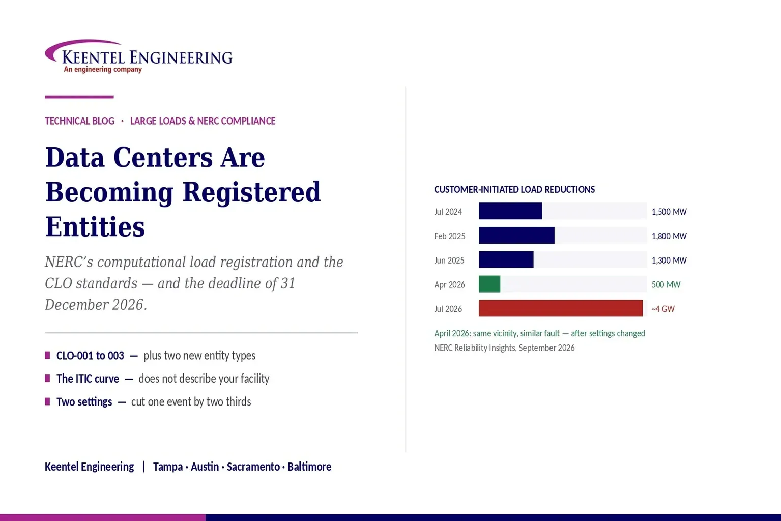
Learn how NERC computational load registration impacts data centers, CLO standards, ride-through requirements, modeling, and grid reliability compliance.
By SANDIP R PATEL
•
September 7, 2026
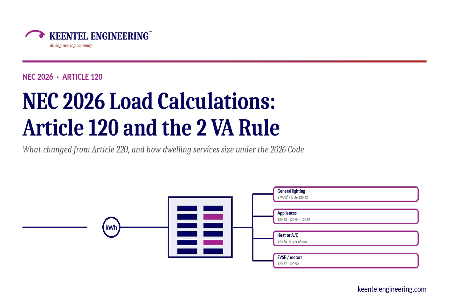
Learn NEC 2026 load calculations, Article 120 changes, the 2 VA rule, EV charging requirements, service sizing, and dwelling calculation methods.
By SANDIP R PATEL
•
September 7, 2026
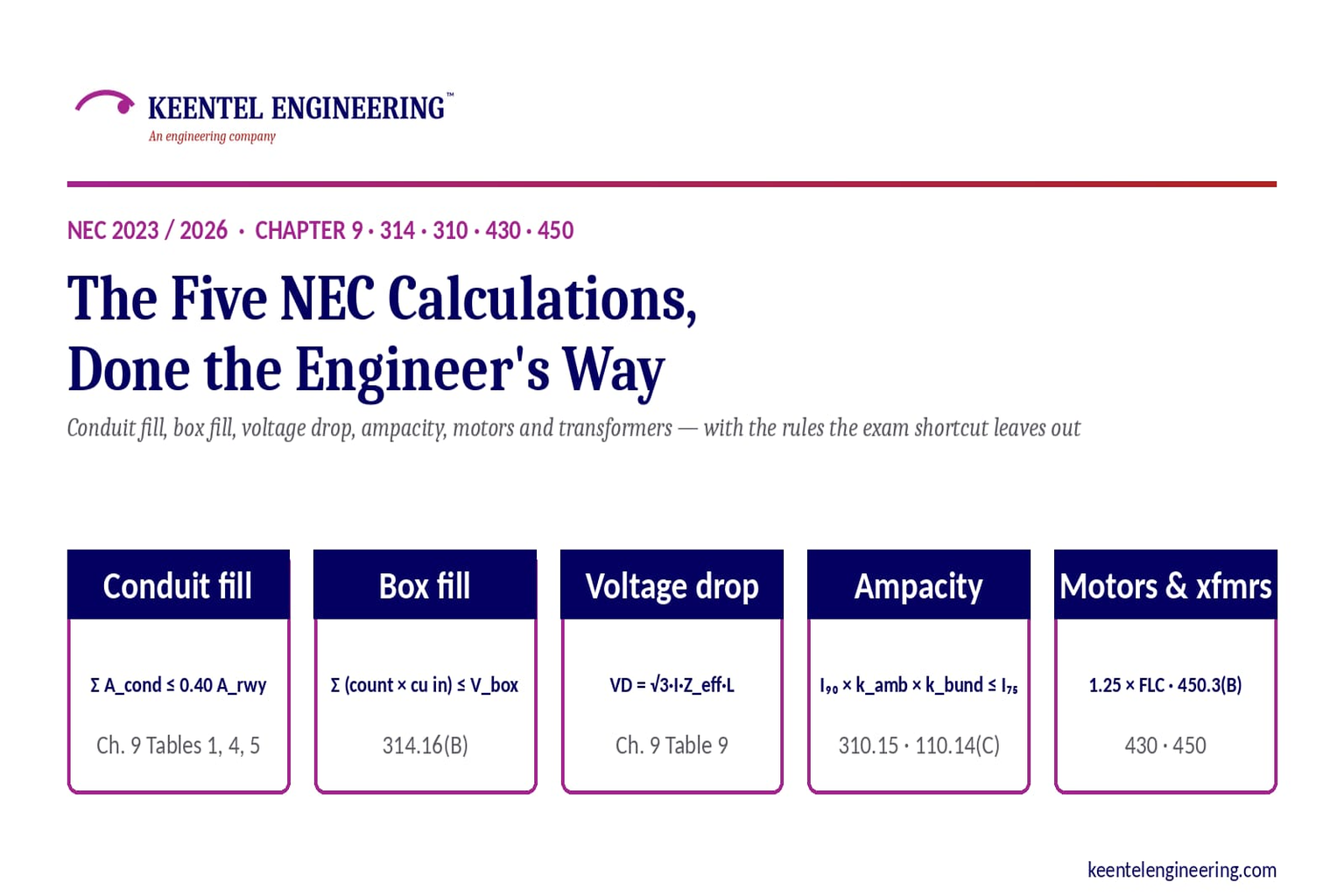
Learn five essential NEC calculations covering conduit fill, voltage drop, ampacity, motor circuits, and transformer protection with engineering examples.
By SANDIP R PATEL
•
September 7, 2026
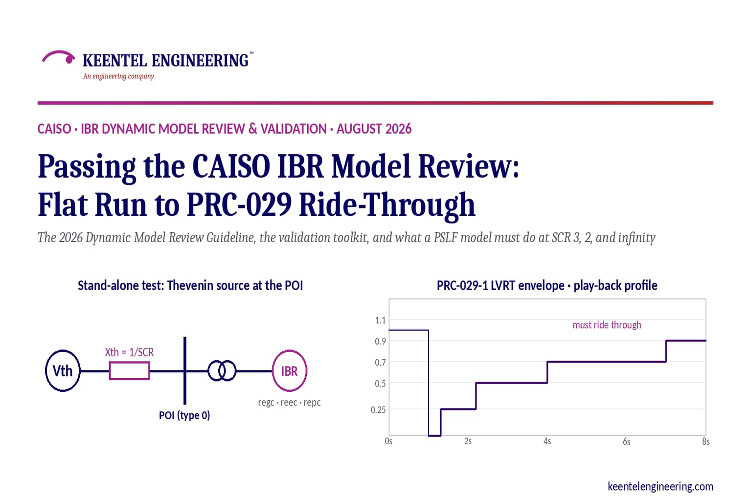
Learn how CAISO reviews IBR models using PSLF validation, PRC-029-1 ride-through requirements, WECC models, and inverter resource compliance testing.
By SANDIP R PATEL
•
September 7, 2026
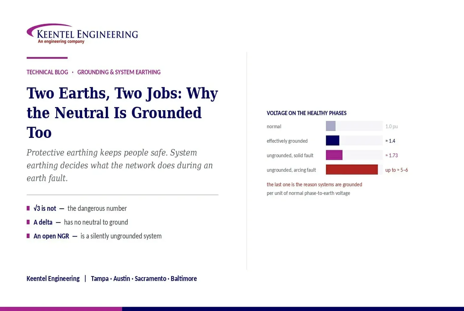
Understand system earthing and protective earthing, neutral grounding methods, effective grounding, ground grids, and insulation coordination for power systems
By SANDIP R PATEL
•
September 6, 2026
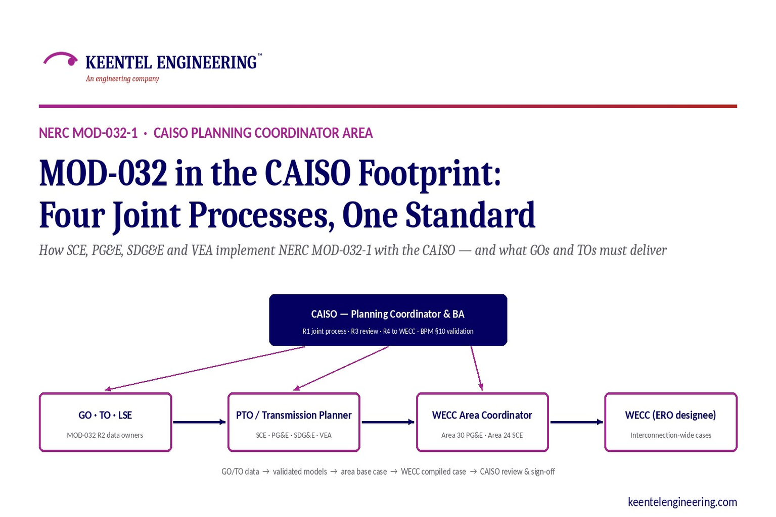
Learn how NERC MOD-032-1 applies across CAISO, SCE, PG&E, VEA and SDG&E, including generator data, PSLF models, EMT requirements and WECC submissions.
By SANDIP R PATEL
•
September 6, 2026
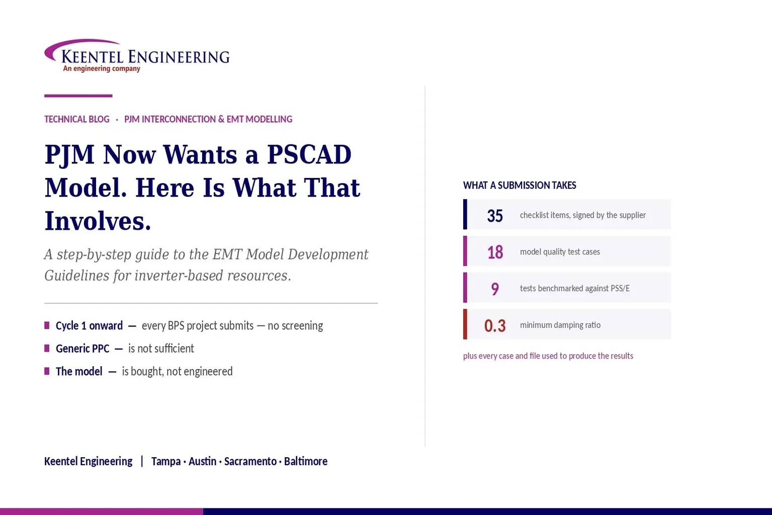
Learn PJM PSCAD model requirements for inverter-based resources, EMT testing, PSS/E benchmarking, ride-through studies, and compliance submissions
By SANDIP R PATEL
•
September 6, 2026
Learn why data center power plants use multiple smaller gas turbines, covering 624 MW capacity, redundancy, grid connection, system strength, and engineering.

By SANDIP R PATEL
•
September 5, 2026
Understand ERCOT BESS interconnection requirements, including model packages, EMT studies, ride-through compliance, telemetry, and real-time co-optimization.





