
A Coordinated Electric System Interconnection Review—the utility’s deep-dive on technical and cost impacts of your project.
Challenge: Frequent false tripping using conventional electromechanical relays
Solution: SEL-487E integration with multi-terminal differential protection and dynamic inrush restraint
Result: 90% reduction in false trips, saving over $250,000 in downtime
The three operating regions you have to design to
| Device | Output vs voltage | Response | Best suited to | Main limitations |
|---|---|---|---|---|
| Mechanically switched capacitor or reactor | Proportional to voltage squared | Seconds; discrete steps; limited switching operations per day | Steady-state reactive supply, voltage profile, loss reduction | No dynamic capability; step voltage change on switching; capability collapses when most needed |
| Static var compensator | Capacitive branches proportional to voltage squared | A few cycles; continuously controllable | Continuous control where cost matters and deep voltage support is not the driver | Square-law capability loss; harmonic filters are part of the plant and interact with the network |
| STATCOM | Approximately proportional to voltage — constant current capability | One to two cycles closed loop; converter response faster still | Voltage stability margin, weak interconnections, fast disturbance recovery, flicker and unbalance compensation | Higher capital cost; converter losses; adds a converter and its control dynamics to the network |
| Synchronous condenser | Governed by machine capability and excitation | Excitation response in the hundreds of milliseconds; inherent inertial response instantaneous | System strength and inertia, short-circuit contribution, black start support | Rotating plant with maintenance and losses; slower controlled response than a converter |
| STATCOM with energy storage | Reactive as a STATCOM, plus real power within the storage rating | As STATCOM for reactive; real power limited by storage | Where a real power deficiency is part of the problem | Cost and complexity of the storage; different failure and maintenance profile |
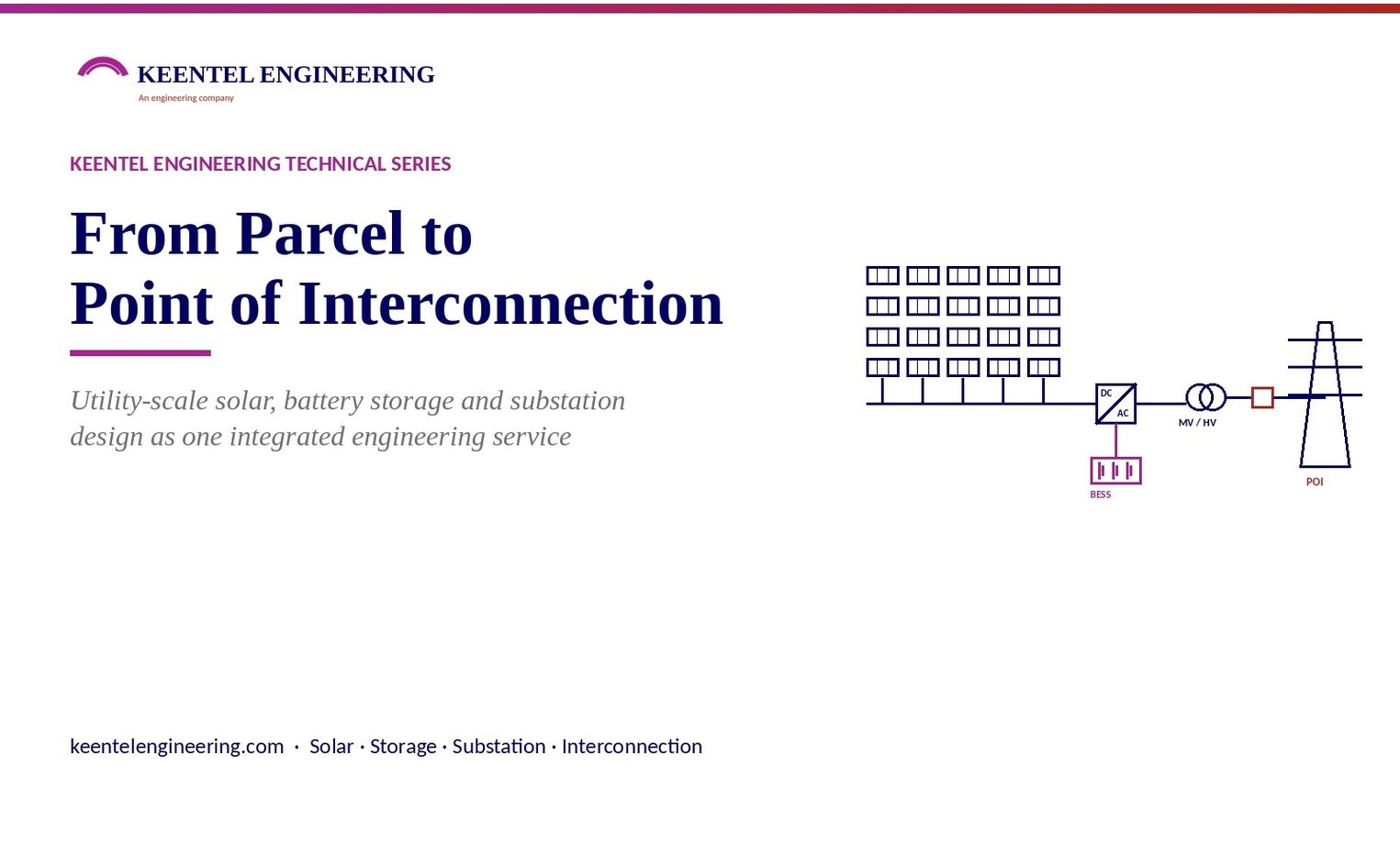
From Parcel to Point of Interconnection
September 19, 2026 | Blog
Utility-Scale Solar, Battery Storage and Substation Design as One Integrated Engineering Service
1. Executive Summary
Utility-scale solar and storage projects are no longer won or lost at financial close. They are won or lost in the first ninety days, when a developer must decide which parcels deserve a deposit, what capacity to request in an interconnection queue, how much storage to pair with the array, and what a defensible capital cost looks like before a single boring has been drilled. The market now demands site-control evidence, commercial-readiness deposits, and increasingly, a technically credible design package at the moment of queue entry. A feasibility study that takes six weeks is a feasibility study that arrives after the window has closed.
Keentel Engineering has expanded its utility-scale renewable engineering practice to deliver the entire front end of a solar, storage or hybrid project as a single, integrated scope: site definition and constraint mapping, automated and optimized photovoltaic plant layout, three-dimensional energy yield, battery energy storage sizing and layout in standalone, AC-coupled and DC-coupled configurations, step-up substation and interconnection facility design, medium-voltage collection and cable sizing to the client's chosen standard, and a complete engineering documentation package including bills of material, capital cost estimates, single-line diagrams, layout drawings and interconnection application support. The same team then carries that preliminary design into detailed engineering, power system studies, protection and NERC compliance, so nothing is lost at the handoff that has historically separated feasibility from execution.
This article explains what the integrated service contains, how each stage is engineered, where automation ends and licensed engineering judgment begins, and how developers, independent power producers, EPC contractors, land originators and lenders use it. A frequently-asked-questions section addresses the practical questions we receive most often, and three composite case studies illustrate the service in use.
1. Why the front end of a project now decides its outcome
For most of the last decade, early-stage solar design was a rough exercise: a desktop estimate of acreage, a rule-of-thumb DC capacity per acre, a spreadsheet yield number and a capital cost taken from the last project. Detailed engineering came later, after the interconnection request was filed and land was secured. That sequence worked when queues were open, deposits were modest and withdrawal penalties were light.
That world has ended. Under the interconnection reforms now in force across the FERC-jurisdictional regions and the parallel process changes in ERCOT, a developer entering a queue is expected to demonstrate site control, post readiness deposits that escalate at each decision point, and accept withdrawal penalties that make an ill-conceived request expensive. Cluster studies compress hundreds of projects into a single cycle, so the capacity requested, the point of interconnection selected and the plant configuration described in the application shape the network upgrade allocation for years. Retracting or resizing a request after the study begins is either impossible or costly.
At the same time, off-takers, lenders and tax-equity investors have become far more sophisticated about energy yield. A P50 number with no loss tree, no module-level shading analysis and no bifacial treatment is no longer accepted at face value. Storage has become the norm rather than the exception, and storage introduces its own sizing, coupling, augmentation and fire-code questions that a rough layout cannot answer.
The consequence is simple: the engineering that used to happen after the interconnection request now has to happen before it. The developer who can produce a credible, optimized, documented design in days rather than weeks screens more parcels, files better requests, bids more work and defends its numbers under diligence.
Keentel's integrated front-end service exists to meet that requirement. It is not a replacement for detailed design; it is the engineering that makes detailed design start from the right answer.
2. What the integrated scope contains
The service is delivered as one scope with one engineering team, covering every discipline between the parcel boundary and the point of interconnection. The table below summarises what is engineered at each stage and what the client receives.
| Stage | What we engineer | What you receive |
|---|---|---|
| Site definition | Parcel and buildable-area mapping, exclusion zones (wetlands, setbacks, easements, floodplain, slope), access roads, existing substations and lines, MV delivery points, topography and cut/fill | Constraint map, buildable-area statement, earthworks estimate |
| Meteorology | Selection and quality review of irradiance and temperature datasets from multiple sources, or client-supplied on-site data | Resource assessment and dataset justification |
| PV plant design | Module, tracker or fixed-tilt structure and inverter selection from an extensive equipment library or client specification; string sizing; DC/AC ratio; row pitch and ground-coverage ratio; block layout; inverter and MV transformer placement; collection circuit routing | Optimized plant layout, electrical configuration, equipment schedule |
| Energy yield | Three-dimensional, module-by-module shading and irradiance analysis including bifacial gain; complete loss tree; P50/P90 production | Energy yield report with hourly production |
| Battery storage | Standalone, AC-coupled or DC-coupled BESS sizing; power and duration optimization; container and PCS placement; augmentation strategy; fire-code separation | BESS layout, sizing basis, coupling comparison |
| MV/LV electrical | Cable sizing and voltage-drop calculation to the client's chosen standard (NEC or IEC); automatic cable length take-off; MV collection and LV single-line diagrams | Cable schedules, SLDs, loss calculations |
| Substation and interconnection | Step-up transformer arrangement and sizing; transformer losses; interconnection facility sizing; gen-tie and overhead line configuration; utility requirements | Substation and interconnection SLDs, overhead line report |
| Documentation | Bill of materials; capital cost estimate; financial indicators; engineering reports; drawings in editable formats | Documentation package in editable form, multiple languages available |
| Interconnection | Data required for interconnection applications in the relevant ISO/RTO or utility process | Application technical exhibits and data sheets |
Every line in that table is engineered on the same site model, so a change to the buildable area automatically propagates to the layout, the yield, the cable schedule, the transformer sizing and the cost estimate. That single-model discipline is what allows Keentel to run many design variants for one site and to compare them on equal terms.
3. Site definition: turning a parcel into a buildable area
A solar layout is only as good as the boundary it is drawn inside. The first engineering task is therefore to convert a legal parcel into an engineered buildable area, and to be explicit about every acre that was removed and why.
Exclusion mapping
We build the site from the parcel outward: wetlands and waters, floodplain, property-line and road setbacks required by the local zoning ordinance, utility easements, pipeline corridors, existing structures, cultural-resource buffers, and any acreage the landowner has reserved. Slope limits are applied by structure type: single-axis trackers tolerate less north-south grade than fixed-tilt racking, and the limit chosen has a direct effect on both earthworks and layout density. The result is a constraint map that documents each exclusion with its source, so the buildable-area number can be defended to a landowner, a county planning board or a lender.
Topography and earthworks
Terrain data is imported at the resolution available, from public elevation models at the screening stage to surveyed contours once the project advances. The terrain is used twice: once to establish the slope-based exclusions and again to estimate cut and fill for access roads, equipment pads and, where the structure type requires it, grading of the array area. Earthworks are frequently the largest unpriced item in a rough feasibility estimate, and an early quantity, even a preliminary one, changes the ranking of sites.
Existing infrastructure and delivery points
Existing substations, transmission and distribution lines, and the medium-voltage delivery points where the collection system will terminate are located on the site model at the outset. The distance from the array to the point of interconnection is a design input, not an afterthought: it determines the length of the gen-tie, whether an on-site step-up substation is required, and how much of the project budget will sit outside the fence.
Parcel screening at portfolio scale
For land originators who hold options on many parcels, the same process is run in a screening mode: a consistent set of exclusion rules is applied to every parcel, a preliminary layout and yield is produced for each, and the portfolio is ranked by buildable capacity, specific yield and distance to interconnection. Parcels that cannot support a viable project are released before a deposit is committed. Clients have described this as reducing their siting effort by a large fraction; the engineering point is that the ranking is consistent, documented and repeatable.
4. Photovoltaic plant design: layout, electrical configuration and optimization
.With the buildable area fixed, the plant is designed as an electrical system first and a field of modules second. Every decision below is made in a form that can be changed and re-run, so the client sees the consequence of each choice rather than a single answer.
Equipment selection
Modules, structures and inverters are selected from an extensive library of current commercial equipment or from the client's own procurement specification. Where a client has a preferred supplier or an existing frame agreement, that equipment is loaded and the design is built around it. Module electrical parameters, temperature coefficients and bifaciality factors, tracker or fixed-tilt geometry, and inverter voltage windows, MPPT ranges and power-factor capability are all carried through to the electrical design.
String sizing and DC/AC ratio
String length is set from the module's open-circuit voltage at the site's design low temperature against the inverter's maximum DC input voltage, and from the maximum-power voltage at the design high temperature against the inverter's MPPT window. The DC/AC ratio is then chosen deliberately. A higher ratio raises energy capture in low-irradiance hours and improves inverter utilization at the cost of clipping at midday; the optimal value depends on the tariff structure, the presence and coupling of storage, and the cost of modules relative to inverters at the time of procurement. We present the ratio as a sensitivity, not a default.
Row pitch, ground coverage and layout density
For trackers, row pitch sets the ground-coverage ratio and therefore the trade between land use and inter-row shading. Backtracking reduces the shading penalty but reduces energy capture at the shoulders of the day. For fixed tilt, the same trade exists between tilt angle, pitch and shading. The layout engine places rows within the buildable area, routes access roads, sites inverter and medium-voltage transformer stations at electrically sensible block centres, and produces the block-by-block equipment count.
Medium-voltage collection and cable sizing
Collection circuits are routed from each inverter station to the delivery point or on-site substation. Cable sizing and voltage drop are calculated to the electrical standard the client selects: the National Electrical Code with its ampacity tables and derating factors for projects in the United States, or the IEC method for international work. DC voltage drop from string to combiner to inverter and AC voltage drop from inverter to transformer to substation are both calculated, and cable lengths are taken off automatically from the routed layout so the bill of material reflects the geometry rather than an allowance.
Optimization across design variants
Because the layout, electrical configuration, yield and cost are all derived from a single model, thousands of variants can be generated and compared: different module sizes, tracker versus fixed tilt, a range of DC/AC ratios, alternative inverter ratings, alternative pitches. Each variant is reported with its installed capacity, specific yield, capital cost and levelized cost of energy, and the client compares them side by side. The engineering value is not in any one variant but in seeing the shape of the trade-off surface for a specific site before committing to a design basis.
A rule of thumb that appears in many early-stage estimates is a fixed number of DC megawatts per acre. On real sites, buildable-area exclusions, slope, row pitch and structure type routinely move that figure by thirty percent or more in either direction. A layout drawn inside the true buildable area is the only reliable way to establish capacity for a queue request.
5. Energy yield: from a single number to a defensible production forecast
The energy yield figure is the number on which the power purchase agreement, the debt sizing and the tax-equity model all rest. It is also the number most easily challenged in diligence. Keentel's yield analysis is built to withstand that challenge.
Three-dimensional, module-level analysis
Rather than treating the array as a uniform plane, the yield model represents every module in three dimensions on the actual terrain and calculates irradiance on each one using ray-tracing. Shading from adjacent rows, from terrain, from trees and structures at the site perimeter and from on-site equipment is resolved module by module, and the electrical consequence of partial shading within a string is captured rather than averaged away. For bifacial modules, rear-side irradiance is computed from ground albedo, row geometry and structure height, so the bifacial gain is a calculated result rather than an assumed percentage.
The loss tree
Production is reported as a full loss tree from plane-of-array irradiance to energy at the point of interconnection: near and far shading, soiling, incidence-angle, spectral, low-irradiance and temperature effects; module mismatch and quality; DC wiring; inverter conversion and clipping; MV transformer and collection losses; step-up transformer losses; availability; and grid curtailment where applicable. Each loss is stated with its basis, so a reviewer can see exactly what was assumed and where the sensitivity lies.
Locating underperformance and fixing it in the design
Because the analysis is module-level, it identifies the specific rows, blocks or edges of the plant that underperform, whether from terrain shading, an unfavourable row orientation on a sloped area, or perimeter obstructions. Those areas are then edited directly in the layout: rows are shifted, pitch is opened, or a low-yield corner is removed from the design and the acreage returned to the landowner. The result is a plant whose specific yield reflects deliberate decisions rather than an average across good and bad ground.
P50, P90 and hourly output
Production is delivered as P50 and P90 annual energy with the uncertainty basis stated, and as hourly production profiles suitable for dispatch modelling, storage sizing and revenue analysis. Off-takers and lenders receive a yield report in which every input can be traced.
6. Battery energy storage: standalone, AC-coupled and DC-coupled
Storage is designed on the same site model as the array, so the interaction between the two is engineered rather than estimated. Keentel designs three configurations and, where the choice is open, compares them for the client.
Standalone storage
A standalone BESS is designed with its own site definition, topography and earthworks, cable sizing, container and power conversion system layout, medium-voltage collection and step-up substation. Sizing is driven by the intended market service: energy arbitrage and capacity in the wholesale market, ancillary services, or a contracted resource-adequacy product. Duration, round-trip efficiency, degradation and augmentation schedule are engineered together, because the augmentation plan determines both the initial oversizing and the space that must be reserved on the pad.
AC-coupled hybrid
In an AC-coupled hybrid the storage has its own power conversion system and connects at the medium-voltage collection bus or at the substation. The PV and storage operate independently, the storage can charge from the grid where the interconnection agreement and tax treatment allow, and either asset can be maintained without affecting the other. The cost is a second set of conversion equipment and a second set of losses. AC coupling is typically the choice when storage is added to an existing plant, when grid charging is valuable, or when the storage must serve markets independently of solar production.
DC-coupled hybrid
In a DC-coupled hybrid the storage connects on the DC side of the PV inverter through a DC-DC converter. Energy that would otherwise be clipped at high DC/AC ratios is captured into the battery, conversion losses are reduced for solar-charged energy, and the shared inverter reduces equipment count. The constraints are that the inverter's AC rating caps the combined output, grid charging may be limited or unavailable, and the control scheme is more complex. DC coupling is typically the choice for new projects with high DC/AC ratios and a solar-charged storage strategy.
Comparing the two
For a new hybrid project, both configurations are designed on the same site and compared on capital cost, annual energy delivered, clipping recovery, losses and the flexibility of operation. The comparison is presented as an engineering trade-off with the numbers behind it, because the right answer depends on the tariff, the interconnection limit and the developer's operating strategy.
Sizing storage for a new or existing plant
Storage capacity and duration are optimized against the plant's hourly production profile, the interconnection capacity limit, the market service and the cost of storage. For an existing plant, the same optimization identifies how much storage can be added without exceeding the existing interconnection agreement and what the incremental energy and revenue would be. Power factor at the point of interconnection is checked against the interconnection requirement with the storage in each operating mode.
Layout, containers and fire code
Container and PCS placement is generated automatically within the storage pad and then reviewed for the separation distances, access and egress requirements of NFPA 855 and the local fire authority, and for the large-scale fire testing basis of the selected enclosure. The layout accounts for future augmentation space, thermal-management equipment, auxiliary power and the routing of DC and AC cabling. Where a jurisdiction's adopted edition of the fire code differs from the current edition, the layout is designed to the adopted edition and the difference is recorded.
Storage that is sized without an hourly production profile, or laid out without the fire-code separations, is storage that will be re-engineered later at greater cost. Both are resolved at the feasibility stage in the integrated scope.
7. Step-up substation and interconnection facility design
The point at which most early-stage design tools stop is the medium-voltage collection bus. Keentel's scope continues through the step-up substation, the gen-tie and the interconnection facility, because that is where the project meets the grid and where the largest single cost items outside the array sit.
Transformer arrangement and sizing
The main power transformer is sized from the plant's AC output at the interconnection with the reactive-power requirement of the interconnection agreement applied, and the arrangement is chosen between a single unit, two half-rated units, or a unit with a spare, according to the availability requirement and the outage exposure the owner is willing to carry. Transformer losses, both no-load and load losses at the plant's expected loading profile, are calculated because they appear in the energy yield at the point of interconnection and in the capitalized cost of losses that a utility or owner may specify.
High-voltage arrangement
The high-voltage side is configured from the interconnecting utility's requirements: the bus arrangement, the presence and type of the interconnection breaker, metering location, disconnect and grounding provisions, surge protection and the interface with the utility's own switchyard where the project connects into an existing station. Keentel's substation design practice covers medium, high and extra-high voltage at 13.8, 34.5, 69, 115/138, 230, 345 and 500 kV and above, and the preliminary design produced at this stage is the same basis that the detailed substation design will carry forward.
Gen-tie and overhead line
Where the plant is remote from the point of interconnection, the gen-tie is engineered as an overhead line or underground cable with its route, structure type, conductor and preliminary sag and clearance basis, and an overhead line design report is produced. The gen-tie length and voltage frequently decide whether an on-site step-up substation is justified or whether the collection system should be brought to a utility-owned station at medium voltage.
Interconnection facility
The interconnection facility, the equipment at the boundary between the project and the utility, is sized and configured to the utility's interconnection standard and to the market's requirements for metering, telemetry, protection and control. The single-line diagram produced at this stage is the one that will appear in the interconnection application and, later, in the facilities study.
8. The documentation package
A design that exists only in a model is of no use to a developer who has to file an application, respond to a request for proposals or present to an investment committee. The integrated scope produces a complete, editable documentation package as its primary output.
| Document | Content | Typical use |
|---|---|---|
| Plant layout drawings | Array, roads, inverter stations, MV routes, substation, storage pad, on the site constraint base | Site plans, landowner discussions, permitting exhibits |
| BESS layout | Containers, PCS, MV transformers, separations, augmentation space | Fire authority review, permitting |
| Single-line diagrams | LV, MV collection, substation and interconnection facility | Interconnection application, utility review, detailed design basis |
| Energy yield report | Resource basis, 3D shading, loss tree, P50/P90, hourly production | PPA negotiation, lender and off-taker diligence |
| Bill of materials | Equipment counts, cable lengths and sizes by circuit, structures, transformers | Procurement enquiries, EPC bid packages |
| Capital cost estimate | Equipment, balance of system, electrical, civil allowance, substation, gen-tie, contingency | Investment screening, bid pricing |
| Financial indicators | LCOE, IRR, NPV and payback from the yield and cost outputs under stated tariff assumptions | Portfolio ranking, board presentation |
| Overhead line report | Route, structures, conductor, preliminary sag and clearance | Gen-tie scoping, right-of-way discussions |
| Interconnection exhibits | Technical data required by the ISO/RTO or utility application | Queue entry, cluster study submission |
| Design comparison | Side-by-side results across design variants | Design-basis decision record |
Drawings are delivered in editable CAD formats and reports in editable document formats, so the client's own engineers and consultants can carry them forward without redrawing. The package can be produced in multiple languages for international projects and partners. Financial indicators are engineering outputs calculated from the yield and cost results under the tariff assumptions the client provides; they are provided to support the client's own financial analysis and are not investment advice.
9. Where automation ends and engineering begins
Design automation is a tool. It allows a small team to explore a large design space quickly, to keep every discipline on one model and to produce documentation that would otherwise take weeks. It does not replace the engineering judgment that makes a design correct for a specific site, utility and jurisdiction. Keentel's position on the boundary is explicit.
| What automation does well | What licensed engineering must still do |
|---|---|
| Generate and compare thousands of layout and electrical variants consistently | Choose the design basis and defend it to a utility, a lender and a permitting authority |
| Calculate cable sizes and voltage drop to a selected standard | Confirm the standard, edition and local amendments adopted by the jurisdiction, and apply the derating conditions that are specific to the installation |
| Size transformers and calculate losses from load profiles | Set the reactive-power, availability and short-circuit basis from the interconnection agreement and the utility's standard |
| Lay out storage containers within a pad | Verify fire-code separations, egress, hazard mitigation analysis and the fire authority's specific conditions |
| Produce an energy yield with a full loss tree | Select and justify the meteorological dataset, the degradation and availability assumptions and the uncertainty basis |
| Produce interconnection data sheets | Select the point of interconnection, the requested capacity and the service type in light of the queue, the transmission system and the network upgrade exposure |
| Estimate cost from quantities | Apply current market pricing, tariff and trade exposure, labour conditions and contingency appropriate to the project stage |
Every deliverable in the integrated scope is reviewed and issued by Keentel's engineering staff. Automated outputs are checked against independent calculation where the consequence of an error is material, and the design basis is recorded so that a reviewer can see which decisions were made by the engineer and why. Civil, structural and geotechnical engineering are coordinated with licensed specialists in those disciplines; the earthworks and foundation quantities in the feasibility package are preliminary engineering estimates for screening, not sealed civil design.
Feasibility-stage design carries the phrase 'basic engineering' for a reason. Its purpose is to make the right decisions early. The value of having the same firm perform both the basic and the detailed engineering is that the decisions made at the front end are the ones the detailed design actually implements.
10. From preliminary design to detailed engineering, studies and compliance
Keentel's practice extends across eleven service lines, and the integrated front-end scope is designed to feed each of them without a change of firm. The preliminary design becomes the basis for the following.
Detailed electrical design
The preliminary layout, equipment schedule and single-line diagrams become the 30 percent design, and are developed through 60 and 90 percent to issued-for-construction packages: DC and AC electrical design, grounding, cable schedules and routing, MV switchgear and transformer specifications, inverter station design, SCADA and communications, and the interface with civil and structural design coordinated with those disciplines.
Substation and transmission line design
The step-up substation preliminary arrangement is developed into full substation design: physical layout, bus and equipment specification, protection and control, grounding to IEEE 80, lightning protection, station service and the interface with the utility. The gen-tie preliminary route and structure basis becomes a full transmission line design with structure loading, sag-tension and clearance analysis and the drawing package.
Power system studies
The interconnection request, and later the facilities study and the utility's model requirements, call for power system studies on the project model: load flow and reactive-capability analysis, short-circuit, dynamic and transient stability, electromagnetic transient modelling for inverter-based resources, harmonic analysis to IEEE 519, and the model validation required by the ISO/RTO. Keentel's study practice covers the voltage range from 4 kV to 765 kV and the modelling platforms used by the North American transmission operators. Because the study model is built from the same design basis as the feasibility package, the studies reflect the plant that will be built.
Interconnection process support
Beyond the application exhibits, Keentel supports the client through the queue: responding to study data requests, reviewing cluster and facilities study results, evaluating network upgrade allocations, and negotiating the technical exhibits of the interconnection agreement. The point-of-interconnection decision made at the feasibility stage is made with that process in view.
Protection, controls and NERC compliance
For projects that will register as generator owners and operators, the design basis established at the front end, ride-through capability, reactive-power capability, protection settings, model quality and monitoring, is the same basis on which NERC compliance will later be assessed under the inverter-based resource standards. Keentel's compliance practice produces the engineering evidence for those standards and can carry a project from its first layout to its first compliance submittal.
Owner's engineer
Where the developer will contract the project to an EPC, the feasibility package becomes the owner's technical specification, and Keentel acts as owner's engineer through procurement, design review, construction oversight, commissioning and performance testing, holding the EPC to the design basis the owner established.
11. Who uses the integrated service, and how
| Client type | Typical use | Value |
|---|---|---|
| Developers | Screen parcels, establish capacity for queue requests, produce the technical basis for site deposits and landowner agreements | Screen parcels, establish capacity for queue requests, produce the technical basis for site deposits and landowner agreements |
| Independent power producers | Add storage to operating plants, evaluate repowering, prepare portfolio-wide design standards | Incremental revenue identified without exceeding existing interconnection |
| EPC contractors | Produce bid designs, quantities and cost estimates quickly enough to respond to more requests for proposals | More bids submitted with engineered quantities rather than allowances |
| Land originators | Rank optioned acreage by buildable capacity and yield before committing deposits | Consistent, documented screening across a large land pipeline |
| Lenders and investors | Independent review of a developer's design basis and energy yield | Traceable yield and cost basis for diligence |
| Utilities and cooperatives | Evaluate utility-owned solar and storage on their own land and distribution assets | Design and cost basis for integrated resource planning |
| Data center and industrial developers | Size on-site or co-located solar and storage against a large load | Behind-the-meter and front-of-meter options compared on one model |
Engagements are scoped by project stage. A screening engagement covers many parcels at a consistent, preliminary level of detail. A feasibility engagement develops one or a few sites to the full documentation package. A pre-application engagement adds the interconnection exhibits and the point-of-interconnection evaluation. Each level is priced to the deliverables, and the work product of one level is the starting point of the next.
12. Composite case studies
The three cases below are composites assembled from the kinds of engagements Keentel undertakes. They are illustrative and do not describe any specific client, site, project, manufacturer or utility.
Case A: Ranking a multi-parcel land pipeline before deposits
A developer held options on fourteen parcels across two states totalling several thousand acres, with a deadline to commit deposits on the parcels it intended to keep. A consistent exclusion rule set was agreed with the developer and applied to every parcel; slope limits were set for single-axis trackers. A preliminary layout, yield and distance-to-interconnection figure was produced for each parcel within days. Five parcels fell below the developer's minimum viable capacity once wetlands, setbacks and slope were removed; two others were viable only with a gen-tie long enough to change the economics. The developer retained seven parcels and released the rest before the deposit deadline. Two of the retained sites were then developed to full feasibility packages for queue entry.
Case B: Choosing between AC and DC coupling for a new hybrid
An independent power producer planned a solar-plus-storage project in a market where the interconnection capacity was fixed by the queue position at a value well below the array's DC capacity. Both an AC-coupled and a DC-coupled hybrid were designed on the same site with the same interconnection limit. The DC-coupled design recovered a substantial fraction of the energy that would have been clipped at the high DC/AC ratio, at a lower equipment count. The AC-coupled design allowed grid charging and independent operation of the storage, which the client's market analysis valued. The two designs were presented with capital cost, delivered energy, losses and operating flexibility side by side; the client selected the DC-coupled design with a small AC-coupled block for grid-charged ancillary service, and the combined design became the basis for the interconnection application and the detailed design.
Case C: Adding storage to an operating plant without exceeding the interconnection agreement
An owner of an operating solar plant wished to add storage but was constrained by an interconnection agreement that fixed the maximum output at the point of interconnection and by an existing substation with limited space. The plant's as-built design was loaded, the hourly production profile was reconstructed from operating data, and storage capacity and duration were optimized against the interconnection limit and the market service the owner intended to provide. An AC-coupled block was laid out on an adjacent pad with fire-code separations, connected at the medium-voltage bus, and the substation and transformer loading were checked with the storage in charge and discharge modes. The design established that the storage could be added under the existing agreement as a material modification review rather than a new request, and the documentation package supported that submission.
13. What we need from you to begin
An engagement begins with a short list of inputs. The more of them that are available, the further the first pass will go; none of them is a barrier to starting.
- Parcel boundaries or a site location, with any known exclusions, easements or landowner reservations
- The intended point of interconnection or the utility and voltage level, if known
- Target capacity, or the interconnection capacity available if the queue position is already held
- Any preferred or contracted equipment: modules, structures, inverters, storage enclosures
- The market service intended for storage, if storage is contemplated
- Survey, geotechnical or on-site meteorological data, if any exists
- The stage of the project and the decision the engineering must support
From these inputs Keentel proposes a scope by level, screening, feasibility or pre-application, with the deliverables listed and a schedule measured in days for screening work and in weeks for a full feasibility package with interconnection exhibits.
14. Keentel Engineering services
Keentel Engineering is an electrical power systems and grid interconnection engineering consultancy headquartered in Tampa, Florida, with offices in Austin, Sacramento and Baltimore. The firm's eleven service lines cover the full life of a generation, storage, transmission or large-load project.
| Service line | Scope |
|---|---|
| POI Interconnection Engineering Support | Queue strategy, application exhibits, study support, network upgrade evaluation, interconnection agreement technical exhibits across PJM, MISO, SPP, ERCOT, CAISO, NYISO, ISO-NE and non-ISO utilities |
| Utility-Scale Renewable Energy Engineering | Solar, wind, storage and hybrid projects from site screening and feasibility design through detailed engineering, as described in this article |
| EHV/HV/MV Power System Studies | Load flow, short-circuit, stability, EMT, harmonics, arc flash and model validation from 4 kV to 765 kV |
| Substation Design Services | Physical, electrical, protection and control and grounding design at 13.8 kV through 500 kV and above; civil and structural coordinated |
| Transmission Line Design Services | Route, structure, conductor, sag-tension, clearance and drawing packages for gen-ties and utility lines |
| NERC O&P Compliance Services | Engineering evidence and programme support for registered generator owners and operators, including the inverter-based resource standards |
| Protection & Control Engineering | Scheme design, settings and coordination, IEC 61850, field support for commissioning |
| Owner's Engineer Services | Technical specification, design review, procurement support, construction oversight, commissioning and performance testing |
| Data Center Power Engineering | Large-load interconnection, campus electrical design, co-located generation and storage |
| MEP Engineering Services | Electrical-led building services for control buildings, e-houses and battery rooms; mechanical and plumbing coordinated |
| Nuclear Power Plant Services | Non-safety-related balance-of-plant electrical engineering and transmission coordination |
Firm credentials: NSPE member firm, D-U-N-S registered, IEEE Senior Member leadership, BBB Accredited Business A+. Professional engineering licensure across our active markets; we will tell you before contract if a state license is not held.
15. Frequently asked questions
Q1. What exactly is included in a feasibility-stage design package?
A feasibility package contains the site constraint map and buildable-area statement, the optimized plant layout with equipment schedule, the electrical configuration with LV and MV single-line diagrams and cable schedules, the energy yield report with its loss tree and P50/P90 production, the storage sizing and layout where storage is included, the step-up substation and interconnection facility single-line diagram, the bill of materials, the capital cost estimate, financial indicators under stated tariff assumptions, and a design comparison record showing the variants considered. All drawings and reports are delivered in editable formats.
Q2. How long does a feasibility package take?
Screening of a parcel to a preliminary layout, yield and cost can be completed in days. A full feasibility package for a single site, including storage and substation design and the documentation set, is typically measured in weeks rather than months, with the schedule governed mostly by the availability of client inputs and the number of design variants the client wishes to compare. The addition of interconnection application exhibits and a point-of-interconnection evaluation extends that by the time needed to review the relevant transmission system and queue.
Q3. Can you design the plant around equipment we have already procured or specified?
Yes. Client-specified modules, structures, inverters, transformers and storage enclosures are loaded from their data sheets and the design is built around them. Where the client has no preference, equipment is selected from an extensive library of current commercial products and the selection is documented as a design decision the client can change.
Q4. Which electrical standard do you use for cable sizing and voltage drop?
The standard is selected to match the jurisdiction and the client's requirements. For projects in the United States, the National Electrical Code's ampacity tables and adjustment and correction factors are applied; for international projects, the IEC method is used. The choice is recorded in the design basis, and the calculation covers DC voltage drop from string to inverter and AC voltage drop from inverter through the collection system to the substation.
Q5. How does your energy yield differ from a conventional single-number estimate?
The yield is calculated on a three-dimensional model of every module on the actual terrain using ray-tracing, so shading from adjacent rows, terrain, perimeter obstructions and on-site equipment is resolved module by module, and bifacial rear-side gain is calculated from the geometry and ground albedo rather than assumed. The result is reported as a complete loss tree with each loss stated and justified, with P50 and P90 annual energy and hourly production profiles. Every input is traceable, which is what a lender's or off-taker's reviewer will ask for.
Q6. What is the difference between AC-coupled and DC-coupled storage, and which should we choose?
In an AC-coupled hybrid the storage has its own power conversion equipment and connects at the medium-voltage bus or substation, operating independently of the array and able to charge from the grid where permitted. In a DC-coupled hybrid the storage connects on the DC side of the PV inverter through a DC-DC converter, capturing energy that would otherwise be clipped and sharing the inverter. DC coupling generally suits new projects with high DC/AC ratios and a solar-charged strategy; AC coupling generally suits retrofits, grid-charging strategies and independent market operation. For a new hybrid we design both on the same site and compare them on cost, delivered energy, losses and operating flexibility so the choice is made on numbers.
Q7. Can you size storage for an operating plant without changing its interconnection agreement?
Yes. The as-built plant is modelled, its hourly production is reconstructed from operating data, and storage capacity and duration are optimized against the output limit in the interconnection agreement and the intended market service. The substation and transformer loading are checked with the storage in charge and discharge modes. The resulting package supports the material-modification review the interconnecting utility or ISO/RTO will require, and identifies whether the addition can proceed under the existing agreement.
Q8. Do you address fire code requirements in the storage layout?
The storage layout is generated automatically within the pad and then reviewed by our engineers against the separation, access and egress requirements of NFPA 855 as adopted in the jurisdiction, the large-scale fire testing basis of the selected enclosure, and any conditions imposed by the local fire authority. Where the adopted edition of the code differs from the current edition, the design follows the adopted edition and the difference is recorded. Hazard mitigation analysis and the fire authority's approval are coordinated as part of detailed design.
Q9. Does the scope include the substation, or does it stop at the collection bus?
The scope continues through the step-up substation, the gen-tie and the interconnection facility. The main power transformer is sized and arranged with its losses calculated, the high-voltage arrangement is configured to the utility's requirements, the gen-tie is routed with an overhead line design report, and the interconnection facility is sized to the utility's standard. The substation and interconnection single-line diagram produced at this stage is the one carried into the interconnection application and detailed design.
Q10. Can the preliminary substation design be carried into detailed design by the same team?
Yes. Keentel's substation design practice covers 13.8 kV through 500 kV and above, and the preliminary arrangement produced in the feasibility package is developed directly into the physical layout, equipment specification, protection and control, grounding and drawing package of the detailed design. Civil, structural and geotechnical engineering are coordinated with licensed specialists in those disciplines.
Q11. What do you need to support an interconnection application?
The application exhibits require the plant's electrical configuration and single-line diagram, equipment data, requested capacity and service type, the point of interconnection, and in most regions a preliminary site plan and evidence of site control. The feasibility package produces the technical content directly. Keentel also evaluates the point-of-interconnection choice against the transmission system and the queue, so the requested capacity and location are set with the network upgrade exposure in view.
Q12. Can you run the power system studies the interconnection process will require?
Yes. The study model is built from the same design basis as the feasibility package, so the load flow, short-circuit, stability, electromagnetic transient and harmonic studies reflect the plant that will be built. Keentel's study practice covers 4 kV to 765 kV and the modelling platforms used by the North American transmission operators, and supports the model validation and data submittals the ISO/RTO requires.
Q13. How many design variants do you actually compare?
As many as the decision requires. Because layout, electrical configuration, yield and cost are derived from a single model, thousands of combinations of module, structure, inverter, DC/AC ratio and pitch can be generated and compared on installed capacity, specific yield, capital cost and levelized cost of energy. The client receives a design comparison record showing the variants considered and the basis for the one selected.
Q14. What is a realistic DC capacity per acre?
There is no reliable universal figure. Buildable-area exclusions, slope, structure type, row pitch and module efficiency move the number by thirty percent or more from any rule of thumb. The only dependable way to establish capacity for a queue request or a landowner agreement is to draw the layout inside the true buildable area, which is the first thing the feasibility package does.
Q15. How do you handle topography and earthworks?
Terrain is imported at the best available resolution, from public elevation models at screening to surveyed contours as the project advances. It is used to apply slope-based exclusions by structure type and to estimate cut and fill for roads, pads and, where required, the array area. The earthworks quantity is a preliminary engineering estimate for screening and cost purposes; sealed civil design is coordinated with a licensed civil engineer at the detailed stage.
Q16. What meteorological data do you use?
Irradiance and temperature data are selected from multiple established sources and reviewed for quality and representativeness of the site, or client-supplied on-site measurements are used where they exist. The dataset selection and its uncertainty are documented in the yield report because they are the largest single driver of yield uncertainty and the first question a reviewer asks.
Q17. Are the financial indicators in the package investment advice?
No. Levelized cost of energy, internal rate of return, net present value and payback are engineering outputs calculated from the yield and cost results under tariff and financing assumptions the client provides. They are delivered to support the client's own financial analysis and portfolio ranking. Keentel is an engineering firm and does not provide investment, tax or legal advice.
Q18. Can you deliver the documentation in languages other than English?
Yes. The documentation package can be produced in multiple languages for international projects and partners.
Q19. Do you work with land originators who have not yet chosen a project?
Yes. Portfolio screening applies a consistent exclusion rule set to every parcel, produces a preliminary layout, yield and distance-to-interconnection for each, and ranks the portfolio so deposits are committed only to parcels that can support a viable project. The screening record is documented so the ranking can be revisited as market conditions change.
Q20. How does the feasibility package connect to NERC compliance later?
The design basis established at the front end, including ride-through and reactive-power capability, protection settings philosophy, model quality and monitoring provisions, is the same basis on which a registered generator owner and operator will be assessed under the inverter-based resource standards. Establishing it correctly at the start avoids redesign, and Keentel's compliance practice carries the project from its first layout to its compliance submittals.
Q21. We are an EPC contractor. Can you support bid designs on short notice?
Yes. Bid designs are a primary use of the integrated scope. A layout, electrical configuration, quantities and cost estimate can be produced for a request for proposals in days, and the bill of materials reflects cable lengths and equipment counts taken from the routed layout rather than allowances. Contractors using this approach have been able to respond to substantially more requests with engineered rather than estimated quantities.
Q22. What if our project is outside the United States?
The same scope applies. The electrical standard is switched to the IEC method, the meteorological sources are selected for the region, the fire code basis is set to the local requirement, and the documentation can be delivered in the language of the project. The interconnection requirements are set to the relevant grid code.
Q23. Who reviews and signs the deliverables?
Every deliverable is reviewed and issued by Keentel's engineering staff. Automated outputs are checked against independent calculation where the consequence of an error is material, and the design basis records which decisions were made by the engineer and why. Sealed drawings are issued under professional engineering licensure in the jurisdictions where Keentel holds it, and we will tell you before contract if a state license is not held.
Q24. How is the work priced?
By level and deliverables. Screening engagements are priced per parcel at a consistent, preliminary level of detail; feasibility engagements are priced per site for the full documentation package; pre-application engagements add the interconnection exhibits and point-of-interconnection evaluation. The work product of one level is the starting point for the next, so nothing is paid for twice.
Q25. How do we start?
Send the parcel boundaries or site location, whatever is known about the intended point of interconnection and capacity, any preferred equipment, and the decision the engineering must support. Keentel will return a scope by level with deliverables and schedule. Contact details are on the final page.
16. Standards and references
The services described in this article are performed to the following codes, standards and procedures as adopted in the relevant jurisdiction. Editions were current at the date of publication.
Interconnection and markets
- FERC Order No. 2023 and 2023-A, Improvements to Generator Interconnection Procedures and Agreements (RM22-14)
- Regional transmission organization and independent system operator generator interconnection procedures and cluster study manuals (PJM, MISO, SPP, CAISO, NYISO, ISO-NE) and ERCOT Planning Guide Section 5
Electrical design
- NFPA 70, National Electrical Code, 2023 and 2026 editions, Articles 690, 691, 705 and 706
- IEC 60364 series, Low-voltage electrical installations, and IEC 60287, Electric cables – calculation of the current rating
- IEEE 2800-2022, Standard for Interconnection and Interoperability of Inverter-Based Resources Interconnecting with Associated Transmission Electric Power Systems
- IEEE 1547-2018, Standard for Interconnection and Interoperability of Distributed Energy Resources
- IEEE 519-2022, Standard for Harmonic Control in Electric Power Systems
Storage
- NFPA 855, Standard for the Installation of Stationary Energy Storage Systems, 2023 and 2026 editions
- UL 9540, Energy Storage Systems and Equipment; UL 9540A, Test Method for Evaluating Thermal Runaway Fire Propagation
- IEEE 2030.3-2016, Standard Test Procedures for Electric Energy Storage Equipment and Systems for Electric Power Systems Applications
Substation and transmission
- IEEE 80-2013, Guide for Safety in AC Substation Grounding
- IEEE C57.12.00 and C57.12.90, Standard General Requirements and Test Code for Liquid-Immersed Distribution, Power and Regulating Transformers
- IEEE C2, National Electrical Safety Code, 2023 edition
Energy yield and reliability compliance
- IEC 61724-1, Photovoltaic system performance – Monitoring; IEC TS 61724-3, Energy evaluation method
- NERC Reliability Standards applicable to inverter-based resources, including PRC-028-1, PRC-029-1, PRC-030-1, MOD-026, MOD-027 and MOD-032
17. Start a scope
To discuss a screening, feasibility or pre-application engagement, contact Keentel Engineering at
contact@keentelengineering.com or (813) 389-7871, or schedule a fifteen-minute call at
calendly.com/keentel-engineering/15min.

About the Author:
Sandip "Sonny" R. Patel, P.E.
IEEE Senior Member · Founder & CEO, Keentel Engineering
In 1995, Sonny Patel earned his Electrical Engineering degree from the University of Illinois. But degrees don't build legacies — action does.
For three decades, he has worked the power industry from every side of the table: 16 years as a utility engineer at Exelon/Commonwealth Edison; generation leadership across hydroelectric, industrial steam turbine, and a 9 GW renewable fleet; NERC Regional Entity Senior Compliance Engineer and Audit Team Lead, auditing some of the nation's largest utilities; and testing and commissioning lead on equipment up to 765 kV — the very top of the North American grid.Utility. Generator. Regulator. Consultant. Few engineers have seen all four seats. Fewer still have sat in them.
His experience spans nuclear, hydro, conventional generation, renewables, oil and gas, mining — and today's data centers, where he is authoring a three-book series on data center design. He is a Licensed Professional Engineer in six states and a Licensed Electrical Contractor in Florida (Unlimited EC) — he doesn't just design the work; he's qualified to stand behind its execution.Today, as Founder and CEO of Keentel Engineering, Sonny leads a nationwide team of engineers delivering substation design, power system studies, NERC compliance, and commissioning — done right, coast to coast.Three decades. Every side of the table. One standard: accountable engineering.
Services

Let's Discuss Your Project
Let's book a call to discuss your electrical engineering project that we can help you with.
About the Author:
Sandip "Sonny" R. Patel, P.E.
IEEE Senior Member · Founder & CEO, Keentel Engineering
In 1995, Sonny Patel earned his Electrical Engineering degree from the University of Illinois. But degrees don't build legacies — action does.
For three decades, he has worked the power industry from every side of the table: 16 years as a utility engineer at Exelon/Commonwealth Edison; generation leadership across hydroelectric, industrial steam turbine, and a 9 GW renewable fleet; NERC Regional Entity Senior Compliance Engineer and Audit Team Lead, auditing some of the nation's largest utilities; and testing and commissioning lead on equipment up to 765 kV — the very top of the North American grid.
Utility. Generator. Regulator. Consultant. Few engineers have seen all four seats. Fewer still have sat in them.
His experience spans nuclear, hydro, conventional generation, renewables, oil and gas, mining — and today's data centers, where he is authoring a three-book series on data center design. He is a Licensed Professional Engineer in six states and a Licensed Electrical Contractor in Florida (Unlimited EC) — he doesn't just design the work; he's qualified to stand behind its execution.
Today, as Founder and CEO of Keentel Engineering, Sonny leads a nationwide team of engineers delivering substation design, power system studies, NERC compliance, and commissioning — done right, coast to coast.Three decades. Every side of the table. One standard: accountable engineering.
Leave a Comment
Thank you for contacting us.
We will get back to you as soon as possible.
We will get back to you as soon as possible.
Oops, there was an error sending your message.
Please try again later.
Please try again later.
Related Posts
By SANDIP R PATEL
•
September 18, 2026
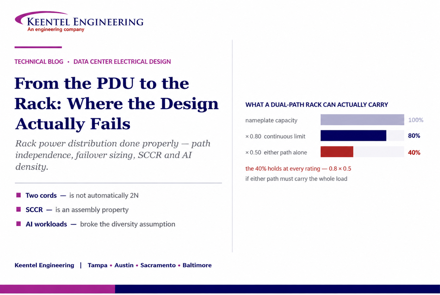
Learn how to size rack power distribution, PDU and RPP systems for continuous loads, A/B redundancy, failover capacity, SCCR and high-density AI data centers.
By SANDIP R PATEL
•
September 18, 2026
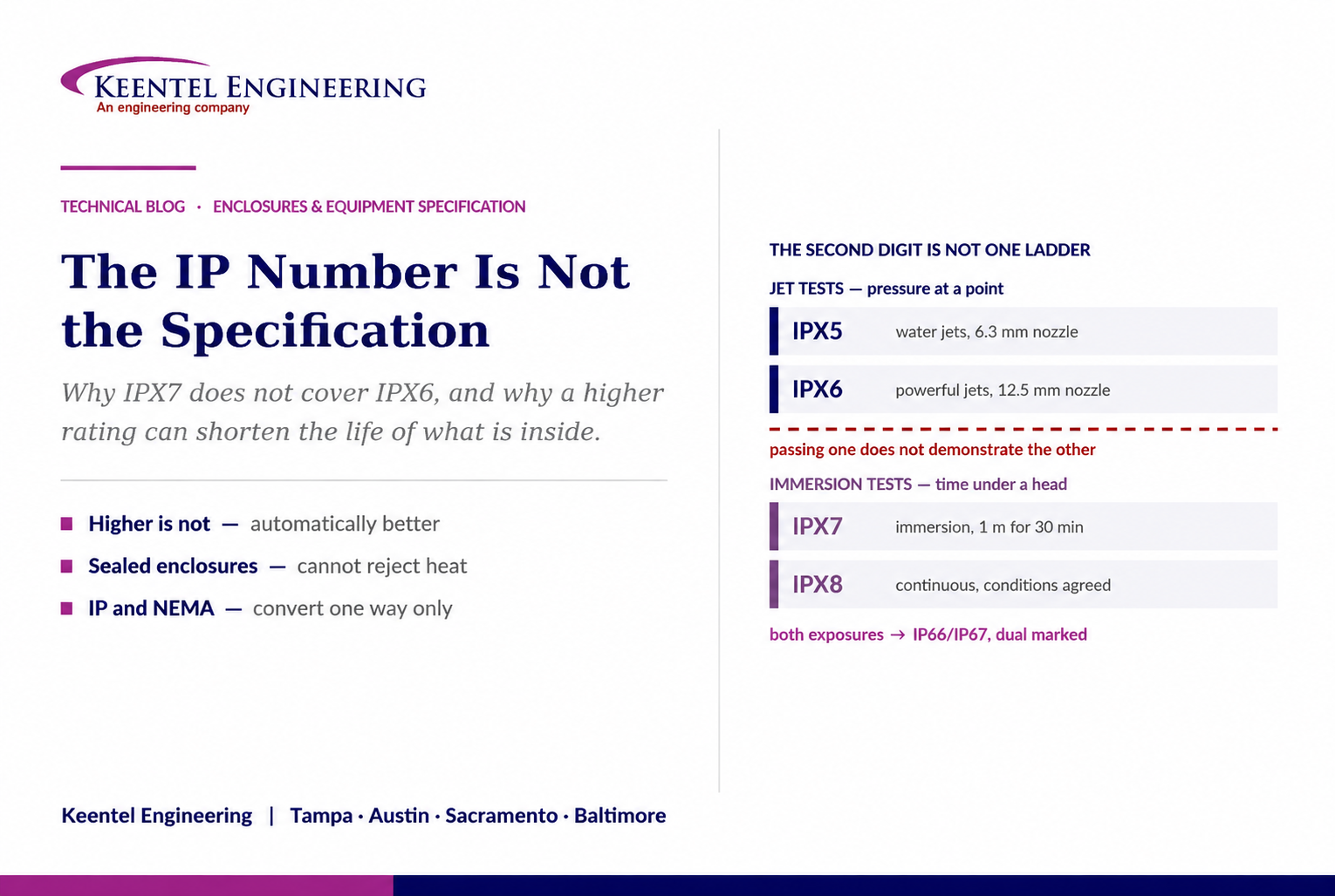
Learn why IP ratings like IP66, IP67, and IP68 do not tell the full story. Understand enclosure selection, NEMA differences, heat, corrosion, and protection.
By SANDIP R PATEL
•
September 9, 2026
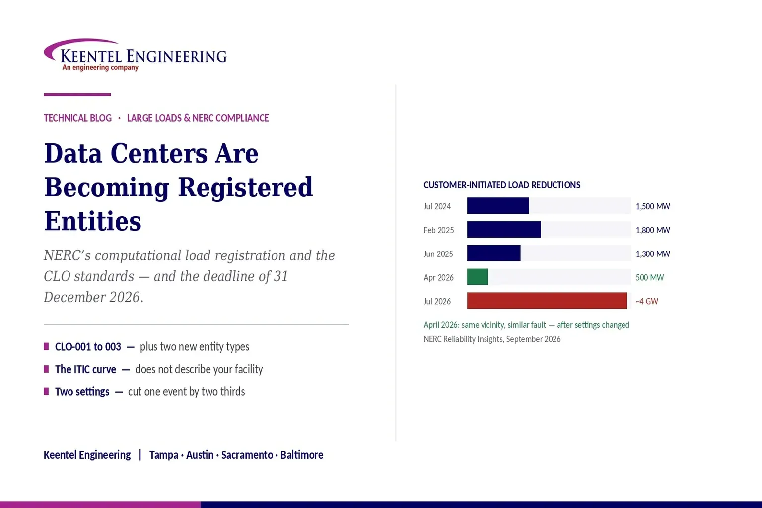
Learn how NERC computational load registration impacts data centers, CLO standards, ride-through requirements, modeling, and grid reliability compliance.
By SANDIP R PATEL
•
September 7, 2026
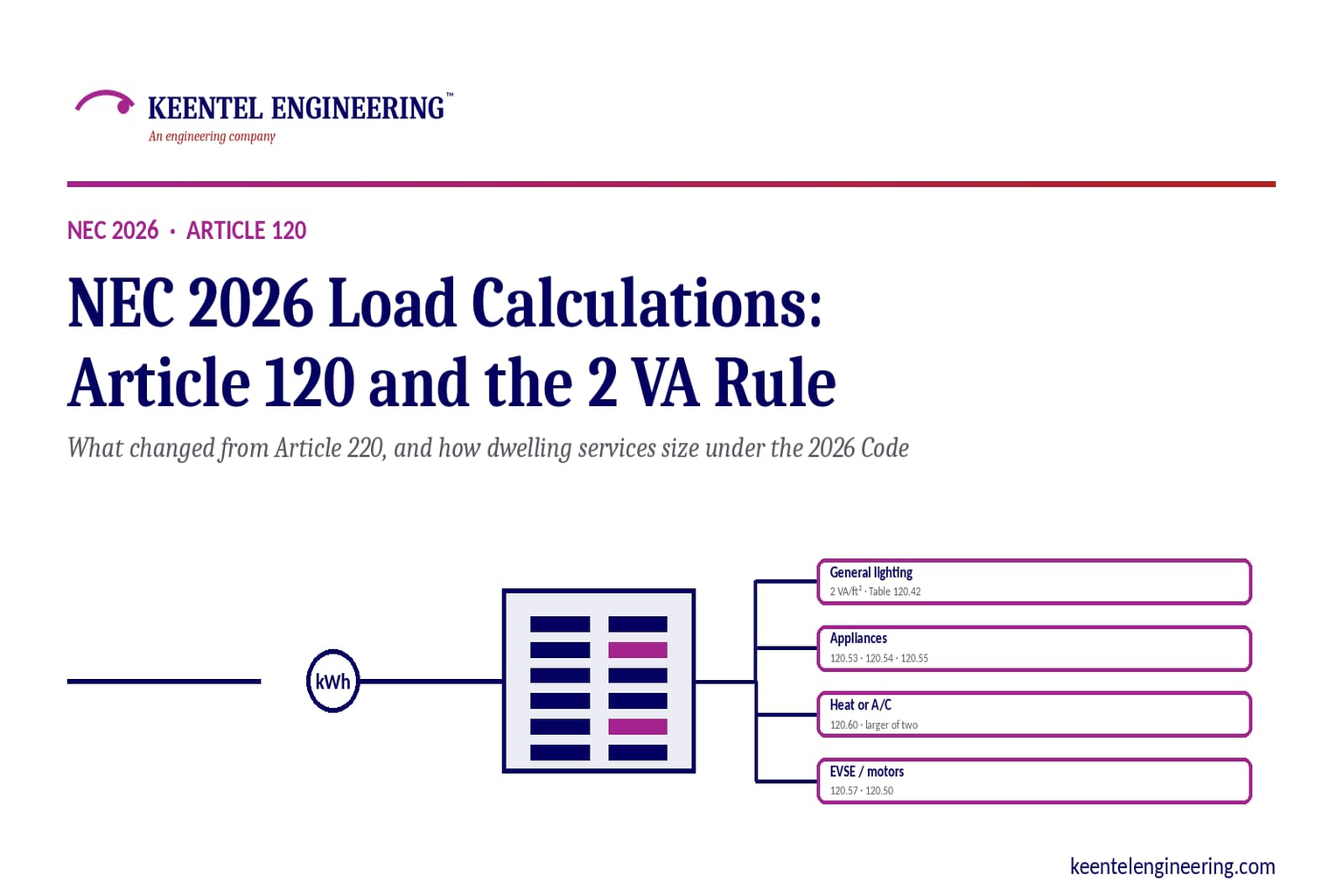
Learn NEC 2026 load calculations, Article 120 changes, the 2 VA rule, EV charging requirements, service sizing, and dwelling calculation methods.
By SANDIP R PATEL
•
September 7, 2026
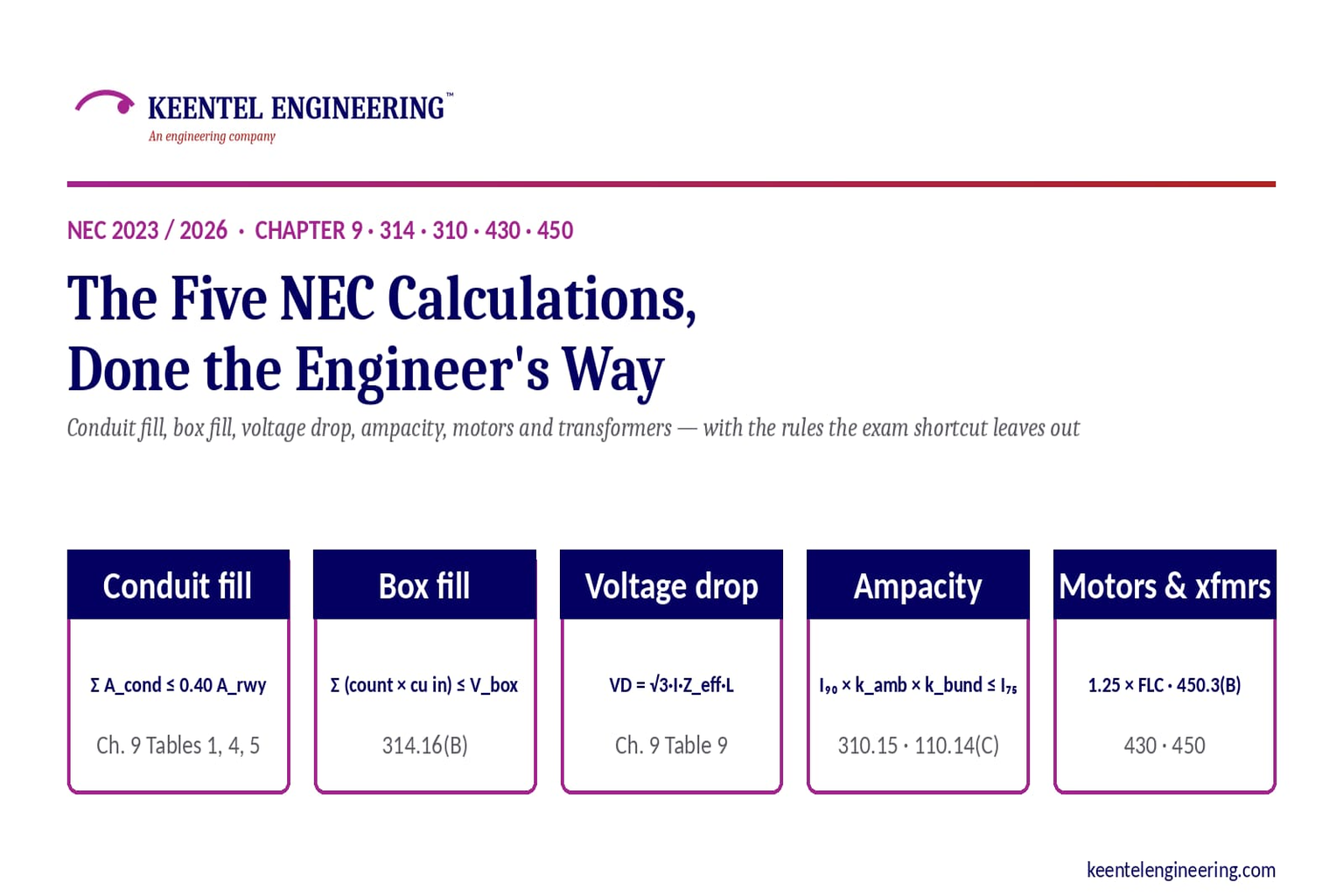
Learn five essential NEC calculations covering conduit fill, voltage drop, ampacity, motor circuits, and transformer protection with engineering examples.
By SANDIP R PATEL
•
September 7, 2026
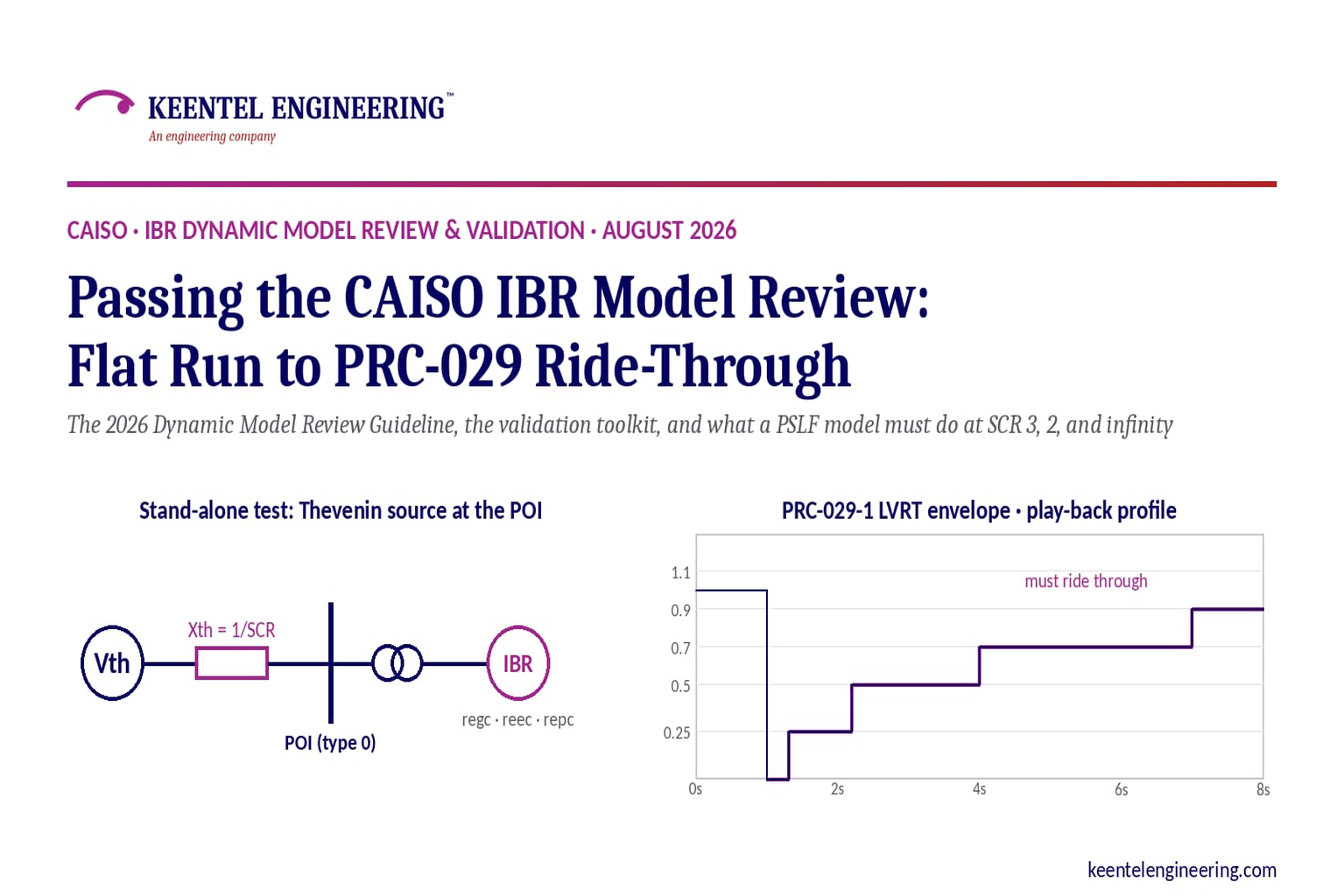
Learn how CAISO reviews IBR models using PSLF validation, PRC-029-1 ride-through requirements, WECC models, and inverter resource compliance testing.
By SANDIP R PATEL
•
September 7, 2026
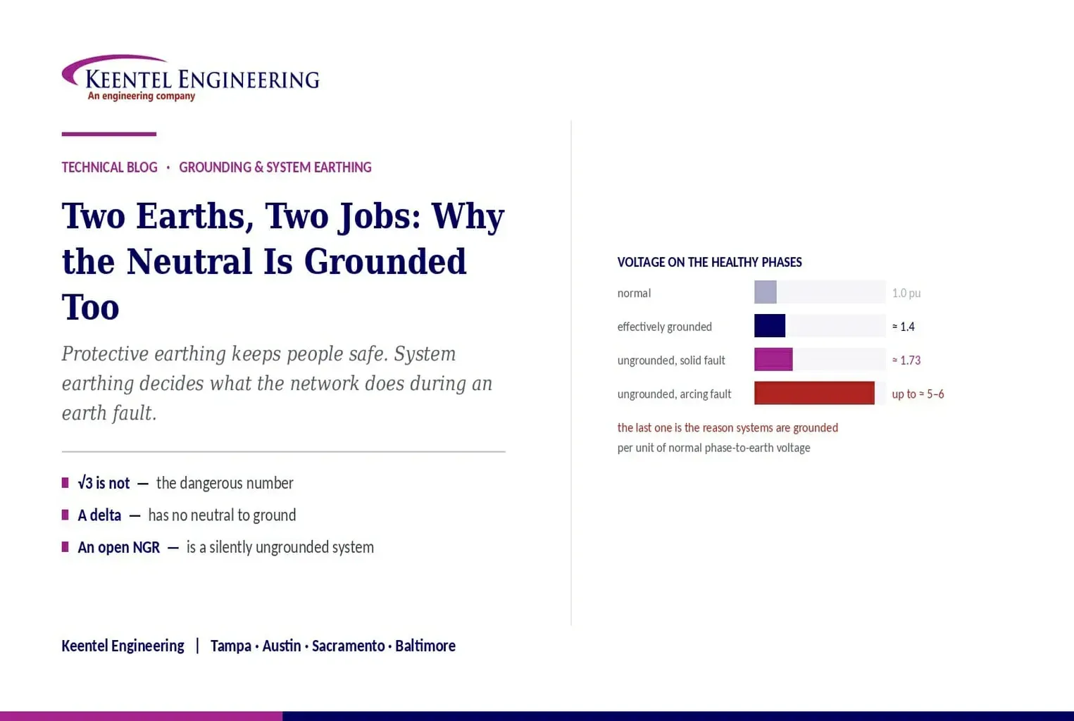
Understand system earthing and protective earthing, neutral grounding methods, effective grounding, ground grids, and insulation coordination for power systems
By SANDIP R PATEL
•
September 6, 2026
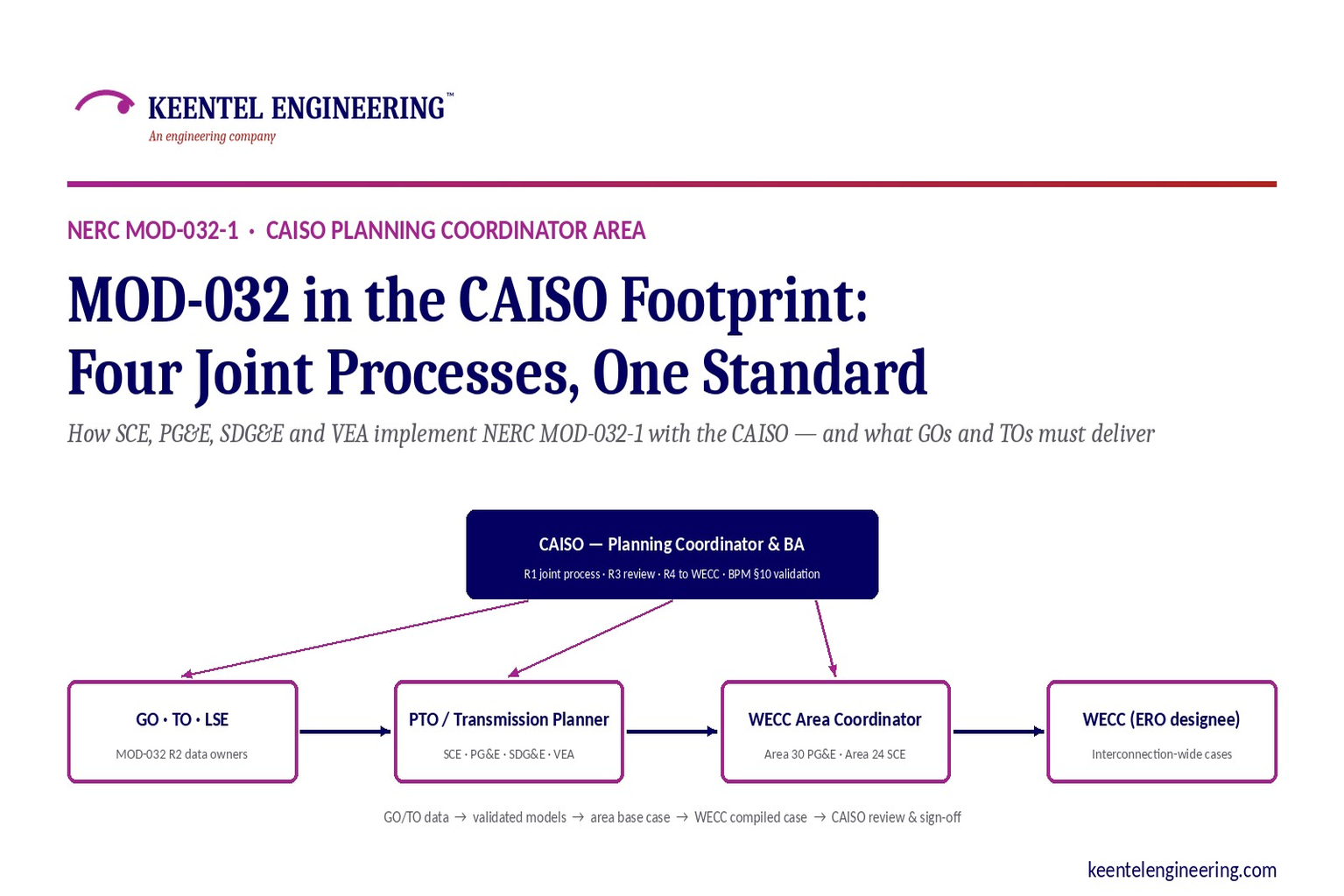
Learn how NERC MOD-032-1 applies across CAISO, SCE, PG&E, VEA and SDG&E, including generator data, PSLF models, EMT requirements and WECC submissions.
By SANDIP R PATEL
•
September 6, 2026
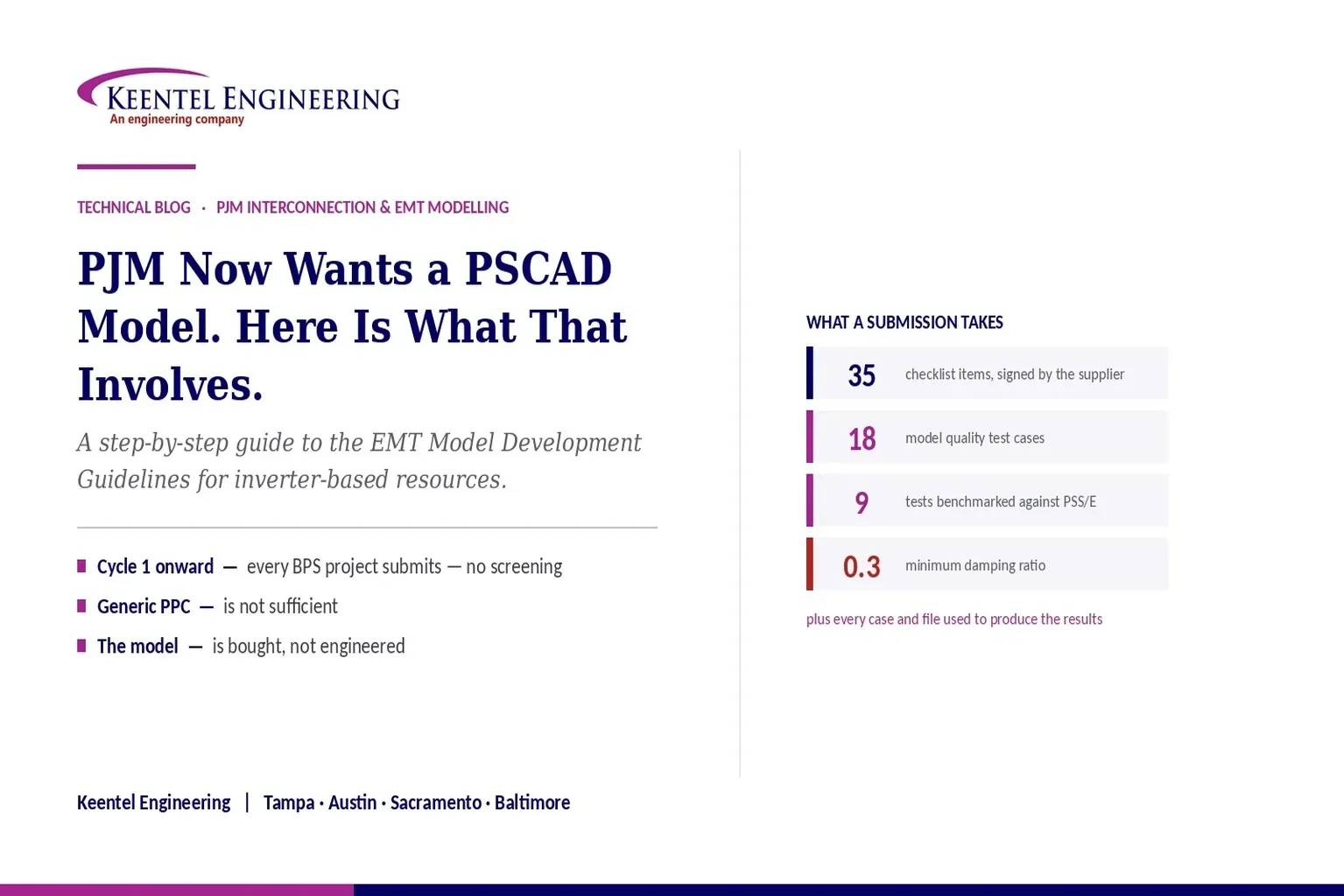
Learn PJM PSCAD model requirements for inverter-based resources, EMT testing, PSS/E benchmarking, ride-through studies, and compliance submissions





