A Coordinated Electric System Interconnection Review—the utility’s deep-dive on technical and cost impacts of your project.
Challenge: Frequent false tripping using conventional electromechanical relays
Solution: SEL-487E integration with multi-terminal differential protection and dynamic inrush restraint
Result: 90% reduction in false trips, saving over $250,000 in downtime
The three operating regions you have to design to
| Device | Output vs voltage | Response | Best suited to | Main limitations |
|---|---|---|---|---|
| Mechanically switched capacitor or reactor | Proportional to voltage squared | Seconds; discrete steps; limited switching operations per day | Steady-state reactive supply, voltage profile, loss reduction | No dynamic capability; step voltage change on switching; capability collapses when most needed |
| Static var compensator | Capacitive branches proportional to voltage squared | A few cycles; continuously controllable | Continuous control where cost matters and deep voltage support is not the driver | Square-law capability loss; harmonic filters are part of the plant and interact with the network |
| STATCOM | Approximately proportional to voltage — constant current capability | One to two cycles closed loop; converter response faster still | Voltage stability margin, weak interconnections, fast disturbance recovery, flicker and unbalance compensation | Higher capital cost; converter losses; adds a converter and its control dynamics to the network |
| Synchronous condenser | Governed by machine capability and excitation | Excitation response in the hundreds of milliseconds; inherent inertial response instantaneous | System strength and inertia, short-circuit contribution, black start support | Rotating plant with maintenance and losses; slower controlled response than a converter |
| STATCOM with energy storage | Reactive as a STATCOM, plus real power within the storage rating | As STATCOM for reactive; real power limited by storage | Where a real power deficiency is part of the problem | Cost and complexity of the storage; different failure and maintenance profile |
| Stage | Keentel scope | Outcome |
|---|---|---|
| Screening | Series-compensation proximity, radial contingency review, UIF and short-circuit ratio screening, frequency scans | Early identification of which SSO types apply |
| Detailed studies | PSCAD/EMTDC EMT studies with vendor real-code models, impedance-based and frequency-scan analysis | Clear evidence of stability margins or risk |
| Model quality | EMT model review, benchmarking against positive-sequence models, model acceptance support | Models that system operators accept |
| Mitigation | Control retuning recommendations with vendors, SSDC and bypass logic requirements, protection and monitoring specifications | Practical, coordinated solutions |
| Interconnection support | SSR and SSO study reports for ISO and utility requirements, response to reviewer comments | Fewer delays in the interconnection process |
Resilience: designing CDUs to the facility Tier objective
Liquid cooling makes heat removal more critical, not less. Cold plates hold only seconds of thermal buffer. If TCS flow stops, processors throttle or shut down very quickly. Resilience design must therefore cover:
- Pump redundancy: N+1 pumps at minimum, with automatic changeover.
- CDU redundancy: N+1 CDUs on a common TCS header, or 2N CDUs serving A and B manifolds for fault-tolerant designs.
- Power to CDUs: dual-corded CDUs fed from A and B sources, with pumps and controls on UPS power so coolant keeps flowing through a utility failure and generator start. This is the liquid-cooling equivalent of continuous cooling.
- Facility water continuity: chilled water or condenser water must also continue, through thermal storage, UPS-backed pumps or a high enough FWS temperature that the TCS can coast on stored thermal mass for the transfer period.
- Concurrent maintainability: isolation valves so any CDU, pump, filter or manifold section can be serviced without stopping the others.
- Leak management: leak detection, drip trays, automatic isolation valves and procedures for fluid spills.
Electrical engineering considerations
CDUs and liquid-cooling plants are electrical loads with their own design requirements:
- Pump motors and VFDs. Large CDUs use variable-frequency drives on their pump motors. These introduce harmonic current that must be included in the facility's harmonic study and IEEE 519 evaluation.
- Critical mechanical load on UPS. Putting CDU pumps on UPS increases UPS and battery sizing. The mechanical UPS load must be included in redundancy and ride-through calculations.
- Feeder and protection design. Dual feeds, automatic transfer, selective coordination and arc-flash labelling apply to CDU power distribution just as they do to IT power.
- Generator transient response. CDU pumps restarting together after a transfer create motor inrush on the generators. Staged restarts and soft acceleration reduce the step load.
- Load dynamics. AI training loads can swing rapidly between high and low power. Cooling controls must track those swings without temperature overshoot, and electrical systems must handle both the IT and the cooling load changes.
Commissioning a liquid-cooled data hall
- Flush and clean the TCS piping and manifolds to the specified cleanliness, using high-purity flush water.
- Fill and vent with the specified coolant, verifying glycol concentration and chemistry.
- Pressure test for leaks at design and test pressures, including quick-disconnect fittings.
- Verify sensors and controls: flow meters, temperature sensors, pressure transmitters, leak detection and BMS points.
- Load test with heat load banks connected through the cold-plate interfaces or rack manifolds, across the operating range.
- Prove the heat balance on both loops at several load steps, and the approach temperature against the design.
- Test failure scenarios: pump failure, CDU failure, power transfer to generator, valve failure and loss of facility water, confirming temperatures stay within the IT vendor's limits.
How Keentel Engineering helps
Keentel Engineering supports data center owners, developers and EPCs with the electrical engineering that liquid-cooled facilities depend on, and coordinates with the mechanical engineer of record and cooling vendors on the integrated design.
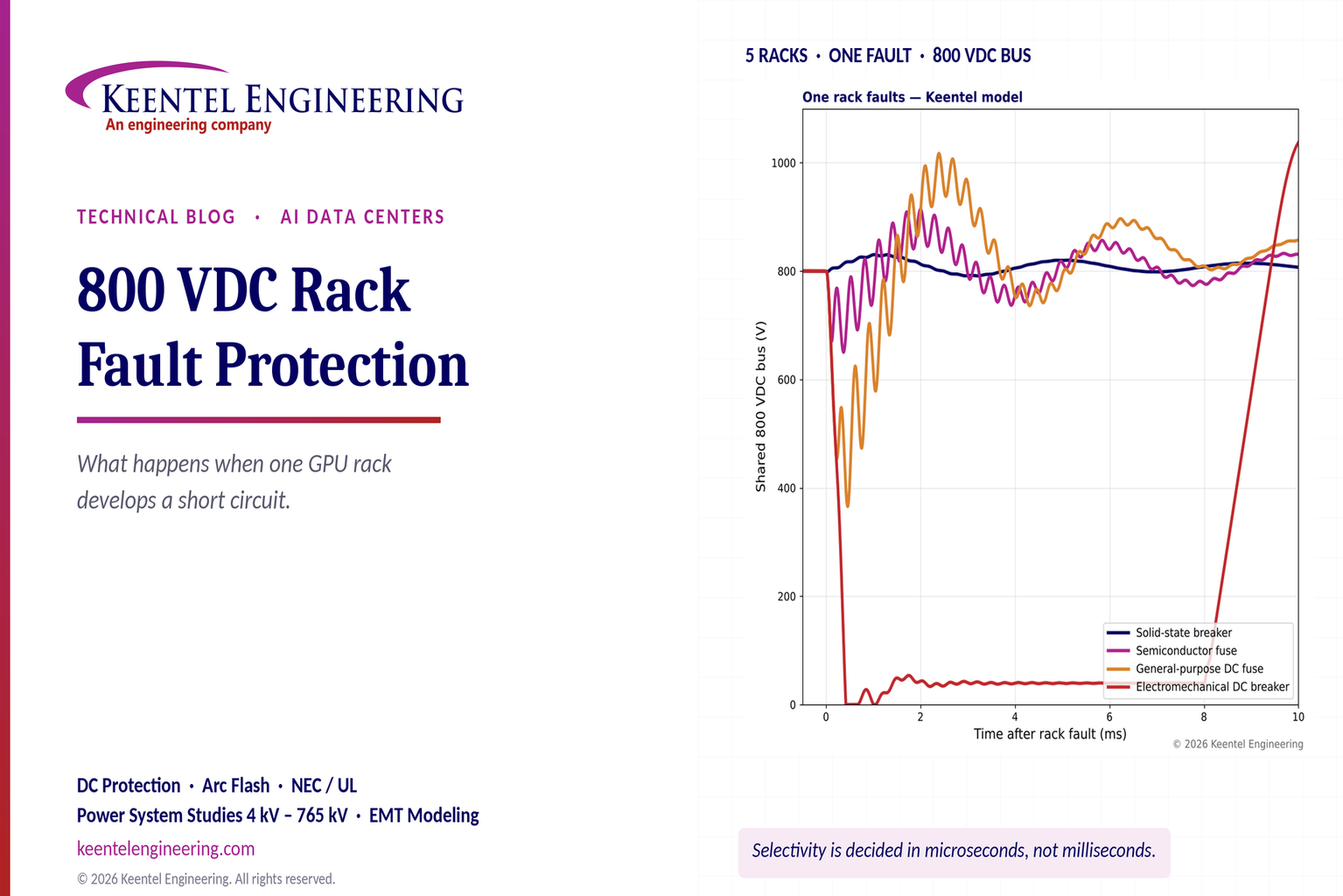
800 VDC Rack Fault Protection: AI Data Center DC Breakers, Selectivity & Safety
October 24, 2026 | Blog
Part A — 800 VDC Rack Fault Protection at a Glance
AI data centers are moving to 800 VDC power distribution. GPU racks now draw several hundred kilowatts each and are heading toward one megawatt. Delivering that power at 54 VDC inside a rack — or at 415 VAC to many small rectifiers — takes enormous amounts of copper and conversion hardware. Distributing 800 VDC to the row or rack cuts conductor current, reduces copper by roughly 45% for the same power, and removes conversion stages.
It also changes the protection problem. A DC bus has no natural current zero, its capacitors can deliver tens of kiloamperes in a fraction of a millisecond, and the racks it feeds are power electronic loads with little tolerance for voltage dips. When one rack develops a short circuit, the question is not only whether the fault is cleared, but whether the other racks on the same bus keep running.
The scenario
Five GPU racks share one 800 VDC bus (+400 V and −400 V conductors referenced to a midpoint). Rack 3 develops an internal short circuit between its positive and negative conductors.
| Stage | What happens |
|---|---|
| 1. Normal operation | Current flows from the source on the positive conductor, through each rack and back on the negative conductor |
| 2. Fault | A low-impedance path forms inside Rack 3; current rises at a rate set by loop inductance, fed first by bus and rack capacitors and then by the source |
| 3. Detection and interruption | Rack 3's protective device detects the overcurrent and interrupts it, absorbing the energy stored in the circuit inductance |
| 4. Isolation | Rack 3 is disconnected; the bus recovers |
| 5. Ride-through | Racks 1, 2, 4 and 5 keep running if the bus voltage stays within their ride-through capability |
| 6. Restoration | After inspection and repair, Rack 3 is reconnected, often through a precharge circuit |
What Keentel's simulation shows
Keentel Engineering modeled five 600 kW racks on an 800 VDC bus with 10 mF of bus capacitance, 2 mF at each rack input, 2 µH and 2 mΩ per rack feeder, a current-limited source, and a 5 mΩ fault inside Rack 3. Healthy racks were assumed to drop offline if their input voltage fell below 600 V. Four protective devices were compared.
| Rack 3 protective device | Peak fault current | Clearing time | Minimum bus voltage | Peak bus voltage after interruption | Healthy racks still online |
|---|---|---|---|---|---|
| Solid-state circuit breaker (trip at 2.5 kA; = 3 µs detection) | 3.1 kA | ≈ 30 µs | 791 V | 830 V | 4 of 4 |
| Semiconductor fuse (pre-arc I²t = 20 kA²s) | 26 kA | ≈ 150 µs | 650 V | 914 V | 4 of 4 (marginal: healthy rack minimum 618 V) |
| General-purpose DC fuse (I²t = 200 kA²s) | 46 kA | ≈ 290 µs | 366 V | 1,017 V | 0 of 4 |
| Electromechanical DC breaker (= 8 ms) | 49 kA | ≈ 8 ms | 0 V | 1,046 V | 0 of 4 (healthy breakers also trip on back-feed) |
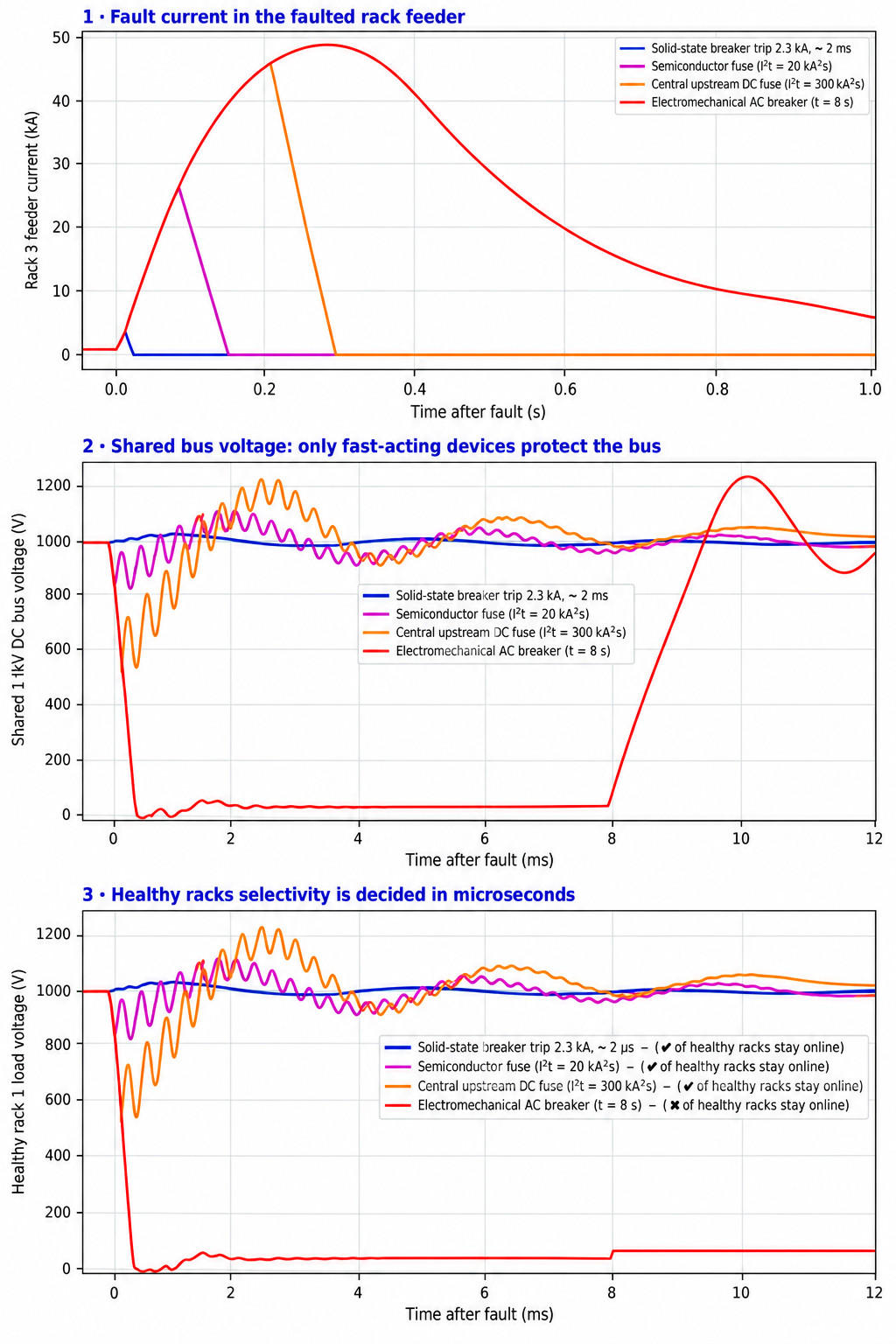
Figure 1. Keentel simulation of a short circuit in Rack 3. Panel 1: fault current in Rack 3's feeder. Panel 2: shared bus voltage. Panel 3: input voltage of a healthy rack.
Four lessons
- Selectivity is decided in microseconds. Bus capacitance alone can drive a fault current of tens of kiloamperes within about 300 µs. Only devices that act before the current builds — solid-state breakers or very fast semiconductor fuses — keep the bus up.
- The bus dip, not the fault current, decides whether the healthy racks survive. Bus voltage must stay above the healthy racks' ride-through threshold for the whole clearing time.
- Interruption creates an overvoltage. The energy stored in circuit inductance (½LI²) must go somewhere: into the breaker's surge absorber, a fuse arc or the bus capacitors. Slow devices let the current, and therefore the stored energy, grow large.
- Healthy racks can back-feed the fault. Rack input capacitors discharge back toward the faulted bus. Without reverse-current blocking or directional protection, healthy-rack devices can trip sympathetically.
Engineering review of a common explanation
The common explanation of this scenario is correct in outline. Several points deserve correction or expansion.
| Common statement | Keentel's check |
|---|---|
| "Positive bus +400 V supplies current; negative bus −400 V provides the return." | Correct for a midpoint-referenced (bipolar) system. Many 800 VDC designs are referenced this way, but some are floating or use high-resistance grounding. The grounding scheme determines what happens in pole-to-ground faults, which are often more common than pole-to-pole faults. |
| Fault path: source (+) → positive bus → Rack 3 protection → short → negative bus → source (−). | Incomplete. In the first hundreds of microseconds, most fault current comes from the bus capacitors and from the input capacitors of the healthy racks, not from the source. The source is usually a rectifier with its own current limit and contributes more slowly. |
| "Rack 3's protection detects excessive current and initiates isolation." | Only correct if the device acts before the bus collapses. An electromechanical breaker cannot do this; a solid-state device or carefully selected semiconductor fuse can. |
| "Protection device opens within milliseconds." | Milliseconds is too slow to keep other racks online in a tightly coupled, capacitive bus. Solid-state breakers interrupt in microseconds; semiconductor fuses in roughly 0.1 to 0.5 ms; electromechanical DC breakers in several milliseconds or more. |
| "All racks except the faulted one continue to run." | Only if the protection is fast enough, the healthy racks have enough ride-through, and back-feed is controlled. Keentel's model shows all four healthy racks dropping when the faulted rack is protected by a general-purpose DC fuse or an electromechanical breaker. |
| "DC interruption is challenging because there is no natural current zero." | Correct. The device must create a counter-voltage higher than the system voltage to force the current to zero, and must absorb the circuit's stored inductive energy. |
| "After inspection and repair, the rack is reconnected and the protection device is reset." | Reconnection should use precharge to limit inrush into the rack's capacitors, which otherwise could draw hundreds of amperes and disturb the bus. |
Part B — Fault Protection for 800 VDC AI Data Centers: An Engineering Guide for US Facilities
1. Why AI data centers are moving to 800 VDC
1.1 The power density problem
GPU rack power has grown from around 10 to 20 kW in traditional enterprise racks to 130 kW and more in current AI systems. Industry roadmaps target racks of about 1 MW by around 2027. At those levels, low-voltage distribution becomes impractical:
| Distribution voltage | Current for a 600 kW rack | Current for a 1 MW rack |
|---|---|---|
| 54 VDC (in-rack busbar) | ≈ 11,100 A | ≈ 18,500 A |
| 415 VAC three-phase (0.95 power factor) | ≈ 880 A | ≈ 1,460 A |
| 800 VDC | 750 A | 1,250 A |
Distributing the same power at 800 VDC instead of 415 VAC reduces current by roughly 15% and eliminates one conductor set. For example, a 3 MW row draws about 3,750 A at 800 VDC on two conductors, compared with about 4,390 A per phase at 415 VAC on three conductors. Conductor losses fall to roughly half:

for equal conductor sizes. Industry analyses report copper savings of around 45% and end-to-end efficiency improvements of a few percent by removing conversion stages.
1.2 Architecture overview
| Element | Function |
|---|---|
| Utility service | 13.8 kV, 34.5 kV, 69 kV, 115 kV or 138 kV service depending on campus size |
| Medium-voltage distribution | 13.8 kV or 34.5 kV switchgear and transformers |
| AC/DC conversion | Large rectifiers in a power room, or solid-state transformers converting medium-voltage AC directly to 800 VDC |
| 800 VDC distribution | Busway or cable from power room to data hall to rows |
| Energy storage | Batteries or capacitor banks on the DC bus to absorb fast GPU load swings and provide ride-through |
| Rack sidecar or power shelf | DC/DC conversion from 800 VDC to the rack's internal voltage (often around 50 V, moving toward higher voltages) |
| Protection | Overcurrent devices at the power room, hall, row and rack boundaries |
Two main configurations are being pursued: row-level 800 VDC busways feeding racks directly, and ±400 VDC "sidecar" racks that convert AC to DC beside the compute racks. Both put protection of a shared DC bus at the center of design.
1.3 Codes and standards landscape in the US
| Code or standard | Relevance |
|---|---|
| NFPA 70 (NEC) Article 645 | Information technology equipment rooms |
| NEC Article 712 | Direct current microgrids, including DC systems with multiple sources and loads |
| NEC Article 706 | Energy storage systems |
| NEC Article 240 | Overcurrent protection, including requirements that devices be rated for DC where used on DC |
| NEC Article 250 | Grounding and bonding, including DC system grounding |
| NFPA 70E | Electrical safety in the workplace, including DC arc flash, DC shock and capacitor hazards |
| UL 489 | Molded-case circuit breakers, including DC ratings |
| UL 2367 | Special purpose solid-state overcurrent protectors |
| UL 248 series | Low-voltage fuses, including fuses for semiconductor protection |
| UL 9540 and UL 9540A | Energy storage systems and fire testing |
| NFPA 75 | Fire protection of information technology equipment |
| IEEE 946 | Recommended practice for DC power systems in stationary applications (useful methods for DC fault and protection analysis) |
Industry specifications for 800 VDC racks are evolving through equipment vendors and open hardware groups. Designers must reconcile emerging vendor requirements with the NEC edition adopted by the local authority having jurisdiction, and with product listings — listed DC-rated protective devices at 800 VDC and multi-kiloampere ratings are still limited in some categories.
2. DC fault fundamentals
2.1 Sources of fault current
A DC distribution bus has three sources of fault current, each with its own time scale:
| Source | Time scale | Magnitude | Notes |
|---|---|---|---|
| Bus and busway capacitance (DC link capacitors, filter capacitors, energy storage capacitors) | Microseconds to about 1 ms | Tens of kiloamperes possible | Limited only by loop inductance and resistance |
| Rack input capacitors of healthy racks | Microseconds to about 1 ms | Several kiloamperes | Flow backward toward the fault |
| Rectifiers or solid-state transformers | About 1 ms and longer | Typically limited to about 1.1 to 2 times rated current by controls | Some diode rectifiers are not current-limited |
| Batteries on the bus | Milliseconds and longer | Very high; limited by internal resistance | A battery can deliver tens of kiloamperes indefinitely until protection acts |
2.2 The capacitor discharge
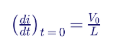
A fault across a charged capacitor C through loop inductance L and resistance R produces an RLC discharge. The initial rate of rise is:
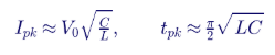
For an underdamped circuit, the peak current and the time to peak are approximately:
2.3 Worked example: bus capacitor discharge
For V0 = 800 V, C = 10 mF and a total loop inductance of 4 µH (feeder plus busway):
| Quantity | Calculation | Result |
|---|---|---|
| Initial di/dt | 800 ÷ 4 µH | 200 A/µs |
| Undamped peak | 800 × √(0.01 ÷ (4 × 10 −6 )) | 40 kA |
| Time to peak | (π/2) × √(4 × 10 −6 × 0.01) | ≈ 0.31 ms |
| Stored energy | ½ × 0.01 × 800 2 | 3.2 kJ |
Resistance reduces the peak; Keentel's full model, which includes source and feeder resistance and rack capacitance, gives about 46 to 49 kA when nothing interrupts the current early. The important point is the time scale: a protective device that waits for "excessive current" over milliseconds will see the full capacitor discharge.
2.4 Worked example: how fast must the device act?
To keep fault current below 3 kA with di/dt of about 200 A/µs from a 750 A load current, the device must begin interrupting within:
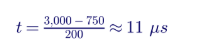
That is achievable only with solid-state detection and switching. A semiconductor fuse begins melting when its pre-arc I²t is reached, typically after tens to a hundred or more microseconds at these rates of rise, by which time current has reached tens of kiloamperes.
2.5 Pole-to-pole versus pole-to-ground faults
| Fault type | Path | Current magnitude | Grounding dependence |
|---|---|---|---|
| Pole-to-pole (+ to −) | Through both conductors | Highest | Independent of grounding |
| Pole-to-ground, solidly grounded midpoint | From one pole to ground and back through the midpoint | High; full half-voltage drives fault | Requires overcurrent protection on both poles |
| Pole-to-ground, high-resistance grounded midpoint | Limited by grounding resistor | Low (often amperes) | Requires ground fault detection; system may continue running with one fault, but voltage to ground on the healthy pole rises |
| Pole-to-ground, ungrounded (floating) | No sustained path | Very low (capacitive) | First fault often undetected without insulation monitoring; second fault on the other pole becomes pole-to-pole |
Grounding choice is therefore a protection decision, not only a safety one.
3. Interrupting DC current
3.1 The fundamental problem
AC breakers interrupt current at its natural zero crossing, 120 times per second at 60 Hz. DC current has no zero crossing. To interrupt DC, a device must generate a voltage greater than the system voltage, driving the current down:

The energy stored in the circuit inductance must be absorbed by the device:
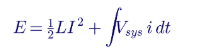
where the second term is the energy the source keeps delivering while the current falls.
3.2 Worked example: energy to absorb
For loop inductance of 4 µH and interruption at 3 kA:

At 46 kA (a slower device), the same inductance stores about 4.2 kJ — more than 200 times as much. Keentel's model shows about 24 J absorbed by the solid-state breaker's surge absorber, about 1.1 kJ in the semiconductor fuse arc, and about 2.5 kJ in the general-purpose fuse arc. Energy absorption drives device size, cost, heat and, for fuses, the risk of arc persistence.
3.3 Protective device technologies:
| Device | Operating principle | Typical interruption time | Advantages | Limitations |
|---|---|---|---|---|
| Solid-state circuit breaker (SSCB) | Semiconductor switches (IGBTs, SiC MOSFETs) turn off current; a metal-oxide varistor or similar clamp absorbs inductive energy | Microseconds | Fastest; limits fault current to near trip level; programmable; resettable | Conduction losses; no galvanic isolation (needs a series mechanical disconnect); cost; thermal management |
| Hybrid DC breaker | Mechanical contacts carry normal current; on trip, current is commutated to a semiconductor path, which turns off | About 0.5 to 2 ms (faster designs exist) | Low conduction losses; galvanic isolation | More complex; slower than pure solid-state |
| High-speed DC circuit breaker (electromechanical, arc chute) | Contacts open and arc is driven into a chute to build arc voltage | Several milliseconds to tens of milliseconds | Mature in traction and industrial DC; galvanic isolation | Too slow to prevent bus collapse in capacitive systems |
| Current-limiting fuse (semiconductor or DC-rated) | Fuse element melts and arcs in sand; arc voltage forces current down | About 0.1 to several ms depending on I²t and fault level | Simple; high interrupting rating; no control power | One-time device; I²t coordination; overvoltage from arc; slow at low fault currents |
| Electronic fuse (eFuse) in power shelves | Semiconductor current limiting at board level | Microseconds | Very fast; integrated | Low power levels per device |
3.4 Solid-state breaker design considerations
| Parameter | Design consideration |
|---|---|
| Rated voltage | 800 VDC nominal, with margin for transients; devices typically rated 1,200 V or 1,700 V |
| Rated current | Rack load current with thermal margin; for 600 kW at 800 V, 750 A |
| Conduction loss | I 2 R of the semiconductor; for 750 A and 1 mΩ, about 560 W per breaker, requiring cooling |
| Trip threshold | Above maximum load and GPU transient peaks, below the level that would sag the bus |
| Detection time | Typically a few microseconds; may use current, di/dt or both |
| Clamp voltage | Above peak system voltage, below device and equipment withstand |
| Energy absorption | ½LI 2 plus source contribution during turn-off, with margin for repeated operations |
| Galvanic isolation | Series mechanical disconnect for safe maintenance |
| Bidirectionality | Required if back-feed must be interrupted |
| Precharge | Controlled reconnection to limit inrush |
3.5 Fuse application in DC
DC fuses must be rated for DC voltage and DC time constant (L/R). A fuse rated for AC at 1,000 V may not interrupt 800 VDC safely. Key parameters:
| Parameter | Meaning |
|---|---|
| DC voltage rating | Must equal or exceed system voltage, at the stated time constant |
| Pre-arc I 2 t | Energy to begin melting; determines when interruption starts |
| Total clearing I 2 t | Energy let through; must be below what downstream and upstream equipment can withstand |
| Peak arc voltage | Overvoltage imposed on the system during interruption |
| Minimum breaking current | Below this current, the fuse may not interrupt reliably |
In Keentel's model, a semiconductor fuse with a pre-arc I²t of about 20 kA²s keeps the healthy racks online, but only just: the healthy rack input voltage dips to 618 V against an assumed 600 V dropout threshold, and peak bus voltage reaches 914 V. A general-purpose fuse with ten times the I²t does not.
4. Selectivity on a shared DC bus
4.1 What selectivity means here
In AC systems, selectivity usually means time–current coordination: the downstream device clears before the upstream device trips. On a capacitive DC bus, selectivity has two more conditions:
- Upstream devices must not trip on the high current that flows through them during the fault and on the back-feed from rack capacitors.
- Healthy loads must ride through the bus voltage dip during the clearing time.
4.2 Voltage dip during clearing
During the fault, the bus capacitor discharges into the fault. For a short clearing time, the voltage dip is approximately the charge removed divided by the bus capacitance:
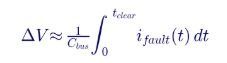
For a linear rise at 200 A/µs over 30 µs (solid-state breaker):

The bus barely moves. For a semiconductor fuse, current rises to about 25 kA over about 90 µs and falls over about 60 µs, removing more than 1.5 coulombs of charge — a dip of well over 100 V, consistent with Keentel's simulated minimum of 650 V once ringing is included.
4.3 Ride-through of GPU power shelves
A rack's ride-through depends on its input capacitance, hold-up energy and the voltage at which its DC/DC converters drop out:
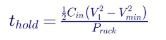
For Cin = 2 mF, V1 = 800 V, Vmin = 600 V and P = 600 kW:

Half a millisecond is enough for a solid-state breaker and a fast semiconductor fuse, but not for an electromechanical breaker. Increasing hold-up requires more capacitance at the rack or bus, energy storage on the DC bus, or lower dropout thresholds in the power shelves.
4.4 Back-feed from healthy racks
When the bus voltage dips, healthy racks' input capacitors are at higher voltage and discharge backward through their feeders toward the fault. In Keentel's model with an electromechanical breaker, back-feed currents reach several kiloamperes and trip the healthy racks' own breakers. Solutions:
| Approach | Effect |
|---|---|
| Fast interruption of the faulted feeder | Keeps the dip small, so back-feed never builds |
| Reverse-current blocking at rack inputs (diodes or ideal-diode controllers) | Prevents rack capacitors from feeding the bus fault |
| Directional protection at rack feeders | Allows healthy-feeder devices to ignore reverse current |
| Feeder impedance (inductance and resistance) | Slows back-feed, at the cost of efficiency and voltage regulation |
4.5 Upstream coordination
Upstream devices — row, hall and power-room protection — carry the total fault current. They must be set to ride through the fault while the rack device clears. For solid-state upstream devices with fast detection, this requires:
- higher trip thresholds upstream than downstream;
- short intentional delays (tens of microseconds) upstream;
- or communication-based coordination, where the rack device signals that it is clearing and upstream devices hold off.
4.6 Worked example: coordinating two solid-state levels
Rack SSCB: trip at 2.5 kA with 3 µs detection. Row SSCB feeding five racks (3,750 A load): trip at 9 kA with 20 µs intentional delay.
| Event | Rack device | Row device |
|---|---|---|
| Fault in Rack 3 at 200 A/µs | Reaches 2.5 kA at about 9 µs, interrupts by about 15 to 30 µs | Sees load current plus fault current, peaking near 3,750 + 3,100 ≈ 6.9 kA, below its 9 kA threshold |
| Fault on the row busway | Not in the fault path | Reaches 9 kA in about 26 µs, then waits 20 µs; current about 13 kA at interruption |
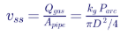
The row device stays selective, but its own interruption current and energy must be rated for the busway fault case.
4A. Distinguishing faults from GPU load transients
AI workloads create large, fast load steps. Thousands of GPUs moving together between compute-intensive and communication phases can swing rack power by a large fraction of its rating in milliseconds, and power shelves may briefly draw currents above their steady rating. A
protective device set too low will trip on normal operation; one set too high will let fault current build.
| Signal | Load transient | Short circuit |
|---|---|---|
| Peak current | Typically up to about 1.2 to 2 times rated, set by power-shelf current limits | Many times rated, limited only by circuit impedance |
| Rate of rise (di/dt) | Limited by power-shelf input inductance and control; typically well below 10 A/µs at the rack | Set by V/L; about 200 A/µs in the examples above |
| Voltage at the rack | Small dip | Collapses toward zero at the fault |
| Duration | Milliseconds, then settles | Grows until interrupted |
Solid-state breakers can combine a current threshold with a di/dt threshold, tripping fast for steep rises while ignoring slower load steps. Settings should be based on measured or vendor-specified GPU load profiles, not on steady-state ratings alone.
Worked example: setting a di/dt element
Suppose the maximum credible load di/dt at a rack is 5 A/µs and the minimum fault di/dt (for a high-impedance fault far into the rack) is 50 A/µs. A di/dt threshold of 20 A/µs, confirmed over 1 µs, separates the two with margin in both directions. A current threshold of 2.5 kA backs it up for faults that rise more slowly than expected. These values are illustrative; real settings come from coordination studies and vendor data.
4B. Source behavior: rectifiers and solid-state transformers
The AC/DC conversion stage shapes the sustained fault current:
| Source type | Fault contribution | Protection implications |
|---|---|---|
| Diode rectifier with transformer | Large, uncontrolled; limited by transformer and AC system impedance | Needs DC-side interruption rated for full prospective current |
| Thyristor-controlled rectifier | Can phase back to limit current within about one cycle | Initial capacitor discharge still dominates the first millisecond |
| Active-front-end (PWM) rectifier | Current-limited by control to about 1.1 to 2 times rated; may block on severe faults | Low sustained fault current may be hard to detect at upstream devices |
| Solid-state transformer | Current-limited by its power electronics; may provide fault-blocking | Protection must coordinate with the converter's own limits |
A current-limited source helps arc flash and equipment duty but complicates upstream fault detection: if the source only provides 1.5 times rated current for a bus fault, an upstream overcurrent device set above that level will never trip. Converter-level protection, undervoltage detection and communication between converter and breakers fill the gap.
5. Transient overvoltage
5.1 Sources
| Source | Mechanism |
|---|---|
| Device clamp voltage | SSCB clamps or fuse arc voltage exceed system voltage during interruption |
| Post-interruption ringing | Inductance and capacitance oscillate after current is interrupted |
| Load rejection | Removing a large rack load suddenly while the source is delivering power |
| Lightning and switching surges from the AC side | Transferred through rectifiers |
5.2 Keentel's results
Peak bus voltage after interruption ranged from 830 V (solid-state breaker) to about 1,046 V (electromechanical breaker, when the source current limit recovers into a de-energized bus). Equipment on the bus must be rated for these peaks with margin. Clamp and surge protective devices (SPDs) are typically coordinated so that the bus stays below the rated voltage of semiconductors in rack power shelves.
5.3 Clamp sizing
For an SSCB with a metal-oxide varistor clamp, the clamp voltage must exceed the maximum system voltage enough to drive current down quickly:
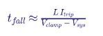
For L = 4 µH, Itrip = 3 kA, Vclamp = 1,300 V and Vsys = 800 V:

A higher clamp voltage shortens interruption but stresses insulation and downstream semiconductors.
6. DC arc flash and shock hazards
6.1 DC arc flash
NFPA 70E requires an arc flash risk assessment for DC systems. A commonly used method for DC incident energy is the maximum power method, which assumes the arc current is half the bolted fault current and the arc voltage is half the system voltage:

with E in cal/cm², V in volts, I in amperes, T in seconds and D in centimeters. This method is conservative. NFPA 70E also notes that arcs in enclosures can direct energy toward the worker, and that multipliers may be applied.
6.2 Worked example: incident energy versus clearing time
For an 800 V bus with a bolted fault current of 40 kA (Iarc = 20 kA) and a working distance of 45.7 cm (18 in), so D² ≈ 2,090 cm²:
| Arc clearing time | Incident energy |
|---|---|
| 0.03 ms (solid-state breaker, assuming arc current reached) | ≈ 0.002 cal/cm 2 |
| 0.3 ms (fast fuse) | ≈ 0.02 cal/cm 2 |
| 10 ms (fast electromechanical device) | ≈ 0.77 cal/cm 2 |
| 100 ms | ≈ 7.7 cal/cm 2 |
| 2 s (slow upstream protection) | ≈ 153 cal/cm 2 |
The fault energy available from capacitors alone is bounded by their stored energy, but battery-backed or rectifier-fed buses can sustain arcs until protection operates. Clearing time is the dominant variable, and fast DC protection is a powerful arc flash mitigation.
6.3 Capacitor hazards
Large DC bus and rack capacitors remain charged after the source is disconnected. NFPA 70E addresses capacitor hazards, including stored-energy thresholds, discharge before work, verification of absence of voltage and grounding of capacitors. Discharge resistors and verified discharge times must be part of the design.
6.4 Shock
800 VDC pole-to-pole and 400 VDC pole-to-ground are well above shock hazard thresholds. Approach boundaries, insulated tools and lockout/tagout procedures apply. Live work on 800 VDC busways in production data halls should be designed out wherever possible.
7. Grounding and ground fault protection
7.1 Grounding options
| Scheme | Description | Ground fault behavior | Considerations |
|---|---|---|---|
| Solidly grounded midpoint (±400 V) | Midpoint bonded to ground | First pole-to-ground fault produces high current; protection trips | Simple detection; both poles need overcurrent protection; voltage to ground limited to 400 V |
| High-resistance grounded midpoint | Midpoint grounded through a resistor | First ground fault produces small current; alarm, continue operation | Requires ground fault location; voltage to ground on the healthy pole can rise toward 800 V |
| Ungrounded (floating) | No intentional ground reference | First fault produces negligible current | Requires insulation monitoring; second fault on the other pole is pole-to-pole |
| Negative pole grounded (0/+800 V) | One pole grounded | Ground faults on the positive pole are high current | Voltage to ground up to 800 V |
The NEC requires DC systems to be grounded or to meet specific requirements for ungrounded operation, including ground fault detection. The choice must balance continuity of service, equipment insulation ratings and personnel safety.
7.2 Worked example: high-resistance grounding current
For a midpoint grounding resistor sized to limit ground fault current to 5 A on a 400 V pole-to-ground voltage:

during a fault. The system can continue operating with one ground fault while maintenance locates it, but the unfaulted pole now sits at up to 800 V to ground, so insulation must be rated accordingly and a second fault must be prevented.
7.3 Insulation monitoring and fault location
Ground fault detection in DC systems uses insulation monitoring devices that inject a low-frequency signal or measure pole-to-ground voltages, together with residual current sensors on feeders to locate the faulted branch. Locating a ground fault in a large data hall without disconnecting racks is a significant operational requirement.
8. Energy storage on the DC bus
8.1 Why storage is added
AI training workloads create fast, synchronized power swings as thousands of GPUs move between compute and communication phases. DC-bus energy storage — batteries, supercapacitors or both — smooths these swings, reduces their effect on the AC grid, and can provide ride-through for upstream disturbances.
8.2 Impact on fault protection
| Effect | Consequence |
|---|---|
| Batteries add sustained fault current | Bus faults are fed until protection opens; arc flash energy rises with clearing time |
| Capacitor banks add initial fault current | Higher peak and di/dt; faster protection needed |
| Storage holds the bus up | Healthy racks ride through longer upstream events |
| Storage converters may be current-limited | If storage connects through DC/DC converters, its fault contribution is controlled |
Every storage installation must have its own overcurrent protection rated for its prospective fault current, and NEC Article 706, UL 9540, UL 9540A and NFPA 855 apply as relevant.
9. Design workflow for 800 VDC protection
- Define the architecture: sources, storage, busway topology, grounding, rack interfaces and ride-through requirements.
- Build a time-domain model: EMT-type simulation including capacitances, inductances, resistances, source current limits, rack load behavior and protective device models.
- Calculate fault currents: peak, rate of rise and sustained current for pole-to-pole and pole-to-ground faults at each location.
- Select devices: SSCBs, hybrid breakers or fuses at each level, with voltage, current, interrupting and energy ratings.
- Verify selectivity: upstream devices hold off; healthy racks ride through; back-feed is controlled.
- Check overvoltage: clamp levels, ringing and SPD coordination.
- Assess arc flash and shock: incident energy, labels, approach boundaries and procedures under NFPA 70E.
- Ground fault design: grounding method, detection and location.
- Code compliance: NEC articles, listed equipment, AHJ coordination.
- Test and commission: device tests, staged fault tests where practical, and protection settings documentation.
9A. Keentel's model in detail
9A.1 Model structure
| Element | Representation | Value used |
|---|---|---|
| Source | Voltage source behind 10 mΩ and 20 µH, with current limit at 1.5 times total rated current | 800 V nominal bus, 3,750 A load, 5,625 A limit |
| Bus capacitance | Lumped capacitor at the bus | 10 mF |
| Rack feeders (×5) | Series inductance and resistance | 2 µH and 2 mΩ each |
| Rack input capacitance | Capacitor at each rack input | 2 mF each |
| Rack loads | Constant-power loads with dropout below 600 V | 600 kW each |
| Fault | Resistance across Rack 3 input | 5 mΩ |
| Solid-state breaker | Trips 3 µs after current exceeds 2.5 kA; clamp at 1,300 V | — |
| Semiconductor fuse | Arcs when pre-arc I 2 t reaches 20 kA 2 s; arc voltage 1,400 V | — |
| General-purpose DC fuse | Arcs when pre-arc I 2 t reaches 200 kA 2 s; arc voltage 1,400 V | — |
| Electromechanical breaker | Opens 8 ms after current exceeds 2.5 kA; arc voltage 1,100 V | — |
9A.2 Sensitivity results
The fast-fuse case is the most sensitive to assumptions. With feeder resistance raised from 2 mΩ to 5 mΩ, the semiconductor fuse's peak let-through falls from about 26 kA to about 25 kA and the healthy-rack minimum voltage rises from 618 V to 630 V. With feeder resistance reduced to 0.5 mΩ and identical fuses at every rack, ringing and back-feed are large enough that healthy-rack fuses can also operate. A design that relies on fuses must therefore be verified with realistic impedances and fuse curves; small changes can flip the outcome from "four racks online" to "none."
The solid-state breaker result is robust across all variations Keentel tested: peak let-through stayed near 3.1 kA, the bus dip stayed below 15 V, and all healthy racks stayed online.
9A.3 What the model leaves out
| Effect not modeled | Expected influence |
|---|---|
| Distributed busway parameters | Traveling-wave effects at microsecond scale; may raise local overvoltages |
| Detailed rack power shelf controls | Constant-power behavior and input current limiting change ride-through margins |
| Energy storage converters | Can add or limit fault current depending on design |
| Pole-to-ground faults | Depend on grounding; not represented in the pole-to-pole model |
| Arc resistance at the fault | Real faults may be arcing with variable resistance, reducing current but sustaining energy release |
| Temperature dependence of fuses | Fuse I²t varies with preloading and ambient temperature |
These effects are addressed in project studies with detailed EMT models.
9B. Selecting protection by level
| Level | Typical current | Recommended technology | Coordination role |
|---|---|---|---|
| Power room (rectifier or SST output) | Thousands to tens of thousands of amperes | Hybrid or solid-state breakers; source current limiting | Backup for hall faults; must ride through downstream faults |
| Hall feeder | Thousands of amperes | Hybrid or solid-state breakers | Backup for row faults |
| Row busway | 2,000 to 6,000 A | Solid-state or hybrid breakers with coordinated delays | Backup for rack faults; primary for busway faults |
| Rack tap | 500 to 1,500 A | Solid-state breakers with series disconnects, or carefully selected semiconductor fuses | Primary for rack faults; must interrupt in microseconds |
| Inside the rack | Tens to hundreds of amperes | eFuses and power-shelf protection | Primary for board-level faults |
The deeper a fault is in the hierarchy, the faster and more local the clearing must be to preserve everything upstream.
10. Worked example: complete rack feeder design
Design the protection for one 600 kW, 800 VDC rack feeder.
| Step | Calculation | Result |
|---|---|---|
| Rated current | 600,000 ÷ 800 | 750 A |
| Continuous rating with 125% factor (NEC practice for continuous loads) | 750 × 1.25 | 938 A; select 1,000 A device |
| GPU transient peak allowance | Vendor-specified peak load, for example 1.5× for a few milliseconds | 1,125 A must not trip |
| SSCB trip threshold | Above transient peaks with margin | 2,500 A |
| Prospective fault di/dt | 800 V ÷ 4 µH | 200 A/µs |
| Peak let-through | Trip current plus di/dt during detection and turn-off | ≈ 3 to 3.5 kA |
| Energy absorbed | ½ × 4 µH × 3,000 2 plus source contribution | ≈ 18 to 30 J |
| Bus dip | From section 4.2 | ≈ 10 V |
| Conduction loss | 750 2 × 1 mΩ | ≈ 560 W |
| Galvanic isolation | Series disconnect switch | Required for maintenance |
| Reconnection | Precharge resistor or soft-start control | Limits inrush to rack capacitors |
The same feeder with a general-purpose fuse would let through more than 40 kA, absorb kilojoules and collapse the shared bus.
11. Testing, commissioning and maintenance
| Activity | Purpose |
|---|---|
| Factory testing of SSCBs | Verify trip thresholds, interruption time, clamp performance and thermal behavior |
| Settings verification | Confirm programmed trip levels and delays match the coordination study |
| Insulation resistance testing | Verify busway and cable insulation before energization |
| Precharge and energization tests | Confirm controlled inrush |
| Staged fault tests (where practical) | Confirm selectivity and ride-through in a controlled setting, often on a test bench rather than the production bus |
| Ground fault detection tests | Verify alarms and location functions |
| Thermal imaging | Detect hot connections on high-current busways |
| Firmware and settings management | Document changes in programmable devices |
| Event recording | Capture high-resolution current and voltage during events for analysis |
12. Common misconceptions corrected
| Misconception | Engineering reality |
|---|---|
| "Any DC-rated breaker will isolate a faulted rack and keep the others running." | Only devices that act within tens of microseconds, or very fast semiconductor fuses, keep a capacitive bus from collapsing. |
| "Fault current comes from the source." | Initially it comes from capacitors on the bus and in healthy racks. |
| "AC fuses and breakers can be used at 800 VDC." | Devices must be specifically rated for DC at the system voltage and time constant. |
| "Selectivity is a time–current curve exercise." | On DC buses, it is also a voltage-dip and back-feed problem solved in microseconds. |
| "A solid-state breaker provides isolation." | Semiconductors do not provide galvanic isolation; a mechanical disconnect is needed for safe work. |
| "Arc flash is an AC problem." | DC arcs are sustained and dangerous; clearing time dominates incident energy. |
| "Grounding is only a safety issue." | Grounding determines ground fault current and protection strategy. |
13. Key takeaways
- 800 VDC reduces current, copper and losses, but makes fault protection a microsecond-scale problem.
- Capacitors dominate the first millisecond of a fault.
- Solid-state breakers keep the bus up; slow devices do not.
- Ride-through and back-feed control are part of protection design.
- Interruption energy and overvoltage must be managed.
- Grounding, arc flash and capacitor hazards require deliberate design.
- Model the system in the time domain before choosing devices.
14. How Keentel Engineering helps
Keentel Engineering supports data center owners, developers, colocation providers and equipment vendors with power system design and studies for AI facilities, from utility interconnection at 13.8 kV to 345 kV through medium-voltage distribution to 800 VDC rack power.
| Service | Keentel scope | Outcome |
|---|---|---|
| Architecture studies | AC versus DC distribution, voltage levels, rectifier and solid-state transformer options, storage integration | Right-sized, efficient architecture |
| DC fault studies | Time-domain modeling of capacitor discharge, source contribution, back-feed and ride-through | Quantified fault currents and dips |
| Protection design | SSCB, hybrid and fuse selection, coordination, clamp and SPD design | Selective protection that keeps racks online |
| Grounding design | Midpoint, high-resistance and ungrounded options; ground fault detection and location | Safe, maintainable systems |
| Arc flash and safety | DC arc flash studies, labeling, NFPA 70E procedures, capacitor discharge design | Compliant, safer work practices |
| Code compliance | NEC Articles 240, 250, 645, 706 and 712; listed equipment strategy; AHJ coordination | Permit-ready designs |
| Utility interconnection | Large-load interconnection studies, substation design, power quality | Grid connection on schedule |
| Commissioning support | Test procedures, settings verification, witness testing | Verified performance |
Why clients choose Keentel Engineering
- Power systems depth from grid to rack: utility interconnection, medium-voltage design and DC distribution under one team.
- Time-domain modeling expertise: EMT and transient studies for fast DC phenomena.
- Practical code knowledge: NEC, NFPA 70E and UL requirements applied to emerging technology.
- Vendor-neutral perspective: independent evaluation of protective devices and architectures.
- Licensed professional engineering: a Florida-registered firm with offices in Tampa, Austin, Sacramento and Baltimore, supporting projects nationwide.
Designing an 800 VDC AI data hall or evaluating DC protection options? Talk to Keentel Engineering at (813) 389-7871, contact@keentelengineering.com, or book a 15-minute scoping call at calendly.com/keentel-engineering/15min.
Part C — Case Studies
The following are illustrative scenarios based on conditions typical of US AI data center projects. They show how Keentel Engineering approaches 800 VDC protection; site details are generalized and figures are rounded.
Case Study 1 — Fuses on a shared row bus that would have dropped the row
Situation. A developer's preliminary design for a 120 MW AI data hall uses 800 VDC row busways feeding eight 600 kW racks each, with DC-rated fuses at each rack tap and molded-case breakers at the row. The owner's requirement is that a single rack fault must not interrupt other racks.
Analysis. Keentel builds a time-domain model of a representative row, including busway inductance, rectifier current limits, row energy storage capacitors and rack input capacitance. With the specified fuses, a rack fault produces more than 40 kA and a bus dip below 400 V for several hundred microseconds — enough to drop every rack on the row. Back-feed from healthy racks also approaches the row breaker's instantaneous setting.
Engineered solution. Keentel recommends solid-state breakers at each rack tap with series disconnects, row-level hybrid breakers with coordinated delays, and ideal-diode reverse blocking in the rack power shelves. Precharge circuits are added for rack reconnection.
Outcome. Simulated rack faults are cleared in about 30 µs with a bus dip of about 10 V, and the owner's single-fault ride-through requirement is met.
Case Study 2 — Grounding decision for a ±400 VDC sidecar architecture
Situation. A colocation provider plans ±400 VDC sidecar power racks for GPU tenants and must decide between solidly grounded and high-resistance grounded midpoints.
Analysis. Keentel evaluates fault currents, protection requirements, insulation ratings and operations for each option. Solid grounding produces high-current ground faults that require two-pole protection and trip the affected rack. High-resistance grounding limits ground faults to a few amperes, allowing continued operation, but requires all equipment insulated for 800 V to ground and a reliable fault location system.
Engineered solution. Keentel recommends high-resistance grounding at 5 A with continuous insulation monitoring and feeder-level residual current sensors, plus alarms that require response within a defined time. Equipment specifications are updated for 800 V to ground insulation.
Outcome. The provider gains continuity of service through single ground faults while keeping a clear path to locate and correct them, and the design is documented for the authority having jurisdiction.
Case Study 3 — DC arc flash at a battery-backed 800 VDC bus
Situation. An AI campus adds battery storage to its 800 VDC busways to smooth GPU load swings. The original arc flash labels were based on rectifier-fed fault currents with fast rectifier current limiting.
Analysis. Keentel recalculates fault currents with battery contribution, which sustains tens of kiloamperes until the busway's upstream protection opens. With the existing upstream device clearing in about 100 ms for busway faults, incident energy at the busway tap boxes exceeds 7 cal/cm² by the maximum power method.
Engineered solution. Keentel specifies fast-acting protection between the battery system and the bus, adds a maintenance mode with reduced trip delay, revises labels and updates energized work procedures under NFPA 70E.
Outcome. Incident energy at the busway falls below 1.2 cal/cm² in maintenance mode, and the campus's safety program reflects the new storage-backed fault conditions.
Part D — Technical FAQ: 800 VDC Fault Protection
To deliver hundreds of kilowatts to one megawatt per rack with less current, less copper and fewer conversion stages than low-voltage DC or 415 VAC distribution.
Initially from bus and rack capacitors, which can deliver tens of kiloamperes in a fraction of a millisecond, then from rectifiers and batteries.
At V/L. For 800 V and 4 µH of loop inductance, about 200 A per microsecond.
DC has no natural current zero. The device must create a voltage higher than the system voltage and absorb the stored inductive energy.
A breaker that uses semiconductor switches to interrupt current in microseconds, with a clamp such as a metal-oxide varistor to absorb inductive energy.
They interrupt before current and bus voltage dip become large. In Keentel's model, a solid-state breaker limited fault current to 3.1 kA and the bus dip to about 10 V.
Very fast semiconductor fuses can, marginally, if the bus capacitance, feeder impedance and rack ride-through are favorable. General-purpose DC fuses usually cannot prevent bus collapse.
They take several milliseconds to build arc voltage, by which time capacitors have discharged into the fault and the bus has collapsed.
Discharge of healthy racks' input capacitors toward the faulted bus. It can trip healthy-rack devices unless blocked or controlled.
Enough to cover the protection clearing time. A rack with 2 mF input capacitance at 600 kW can hold up for about 0.47 ms from 800 V to 600 V.
Device clamp or arc voltage, post-interruption ringing of inductance and capacitance, and load rejection.
No. A series mechanical disconnect is needed for galvanic isolation.
I²R of the semiconductor: about 560 W at 750 A with 1 mΩ on-resistance, requiring cooling.
Solidly grounded midpoint, high-resistance grounded midpoint, ungrounded with insulation monitoring, or one pole grounded. Each changes ground fault behavior and protection needs.
Commonly with the maximum power method referenced in NFPA 70E, which depends strongly on clearing time.
Yes. Batteries can sustain high fault currents, increasing interrupting duty and arc flash energy unless fast protection is applied.
Articles 240, 250, 645, 706 and 712, among others, depending on the installation and the edition adopted locally.
UL 489 for molded-case breakers with DC ratings, UL 2367 for solid-state overcurrent protectors and the UL 248 series for fuses.
Rack input capacitors at zero voltage would draw very high inrush current from the bus, disturbing other racks and stressing devices.
Time-domain modeling of the DC system, including capacitances, inductances, sources, loads and protective devices, before selecting equipment.
References and Further Reading
Links were current at publication (October 2026).
- NFPA 70, National Electrical Code, Articles 240, 250, 645, 706 and 712. National Fire Protection Association.
- NFPA 70E, Standard for Electrical Safety in the Workplace (DC arc flash and capacitor hazards). National Fire Protection Association.
- NFPA 75, Standard for the Fire Protection of Information Technology Equipment; NFPA 855, Installation of Stationary Energy Storage Systems. National Fire Protection Association.
- UL 489, Molded-Case Circuit Breakers; UL 2367, Special Purpose Solid State Overcurrent Protectors; UL 248 series, Low-Voltage Fuses; UL 9540 and UL 9540A. UL Standards & Engagement.
- IEEE Std 946, Recommended Practice for the Design of DC Power Systems for Stationary Applications. IEEE.
- D. R. Doan, "Arc Flash Calculations for Exposures to DC Systems," IEEE Transactions on Industry Applications, 2010.
- NVIDIA, "NVIDIA 800 V HVDC Architecture Will Power the Next Generation of AI Factories," NVIDIA Technical Blog, 2025.
- ABB and NVIDIA, 800 VDC architecture white paper, 2025.
- Open Compute Project materials on high-voltage DC rack power ("Mt. Diablo" ±400 VDC). Open Compute Project.
Disclaimer
This article is general technical information for educational purposes. It is not engineering advice for any specific project and does not create a professional relationship. Keentel Engineering's simulation uses a simplified lumped model with illustrative parameters; actual fault currents, clearing times, ride-through and overvoltages depend on specific equipment, layout, controls and protective device characteristics and must be verified by project-specific study and manufacturer data. Designs must follow the NEC edition adopted by the authority having jurisdiction, NFPA 70E, applicable UL listings and IEEE standards, and project-specific engineering analysis, sealed by a licensed professional engineer where required. Arc flash examples are illustrative and must not be used for labeling.
Case studies are illustrative scenarios based on typical project conditions, not records of specific client projects. Figures are rounded and indicative.
NFPA, NEC, UL, IEEE, NVIDIA, ABB, Open Compute Project and other names are the property of their respective owners. Keentel Engineering is not affiliated with or endorsed by these organizations or any equipment vendor.
| Office | Address | Phone |
|---|---|---|
| Head Office — Tampa | 400 N Ashley Dr STE #2600, Tampa FL 33602 | (813) 389-7871 |
| Austin | 5900 Balcones Drive STE 100, Austin TX 78731 | (512) 591-0752 |
| Sacramento | 1401 21st St Ste R, Sacramento CA 95811 | (916) 913-4524 |
| Baltimore | 306 W Redwood St STE 200, Baltimore MD 21201 | (410) 225-2181 |

About the Author:
Sandip "Sonny" R. Patel, P.E.
IEEE Senior Member · Founder & CEO, Keentel Engineering
In 1995, Sonny Patel earned his Electrical Engineering degree from the University of Illinois. But degrees don't build legacies — action does.
For three decades, he has worked the power industry from every side of the table: 16 years as a utility engineer at Exelon/Commonwealth Edison; generation leadership across hydroelectric, industrial steam turbine, and a 9 GW renewable fleet; NERC Regional Entity Senior Compliance Engineer and Audit Team Lead, auditing some of the nation's largest utilities; and testing and commissioning lead on equipment up to 765 kV — the very top of the North American grid.Utility. Generator. Regulator. Consultant. Few engineers have seen all four seats. Fewer still have sat in them.
His experience spans nuclear, hydro, conventional generation, renewables, oil and gas, mining — and today's data centers, where he is authoring a three-book series on data center design. He is a Licensed Professional Engineer in six states and a Licensed Electrical Contractor in Florida (Unlimited EC) — he doesn't just design the work; he's qualified to stand behind its execution.Today, as Founder and CEO of Keentel Engineering, Sonny leads a nationwide team of engineers delivering substation design, power system studies, NERC compliance, and commissioning — done right, coast to coast.Three decades. Every side of the table. One standard: accountable engineering.
Services

Let's Discuss Your Project
Let's book a call to discuss your electrical engineering project that we can help you with.
About the Author:
Sandip "Sonny" R. Patel, P.E.
IEEE Senior Member · Founder & CEO, Keentel Engineering
In 1995, Sonny Patel earned his Electrical Engineering degree from the University of Illinois. But degrees don't build legacies — action does.
For three decades, he has worked the power industry from every side of the table: 16 years as a utility engineer at Exelon/Commonwealth Edison; generation leadership across hydroelectric, industrial steam turbine, and a 9 GW renewable fleet; NERC Regional Entity Senior Compliance Engineer and Audit Team Lead, auditing some of the nation's largest utilities; and testing and commissioning lead on equipment up to 765 kV — the very top of the North American grid.
Utility. Generator. Regulator. Consultant. Few engineers have seen all four seats. Fewer still have sat in them.
His experience spans nuclear, hydro, conventional generation, renewables, oil and gas, mining — and today's data centers, where he is authoring a three-book series on data center design. He is a Licensed Professional Engineer in six states and a Licensed Electrical Contractor in Florida (Unlimited EC) — he doesn't just design the work; he's qualified to stand behind its execution.
Today, as Founder and CEO of Keentel Engineering, Sonny leads a nationwide team of engineers delivering substation design, power system studies, NERC compliance, and commissioning — done right, coast to coast.Three decades. Every side of the table. One standard: accountable engineering.
Leave a Comment
Thank you for contacting us.
We will get back to you as soon as possible.
We will get back to you as soon as possible.
Oops, there was an error sending your message.
Please try again later.
Please try again later.
Related Posts
By SANDIP R PATEL
•
October 24, 2026
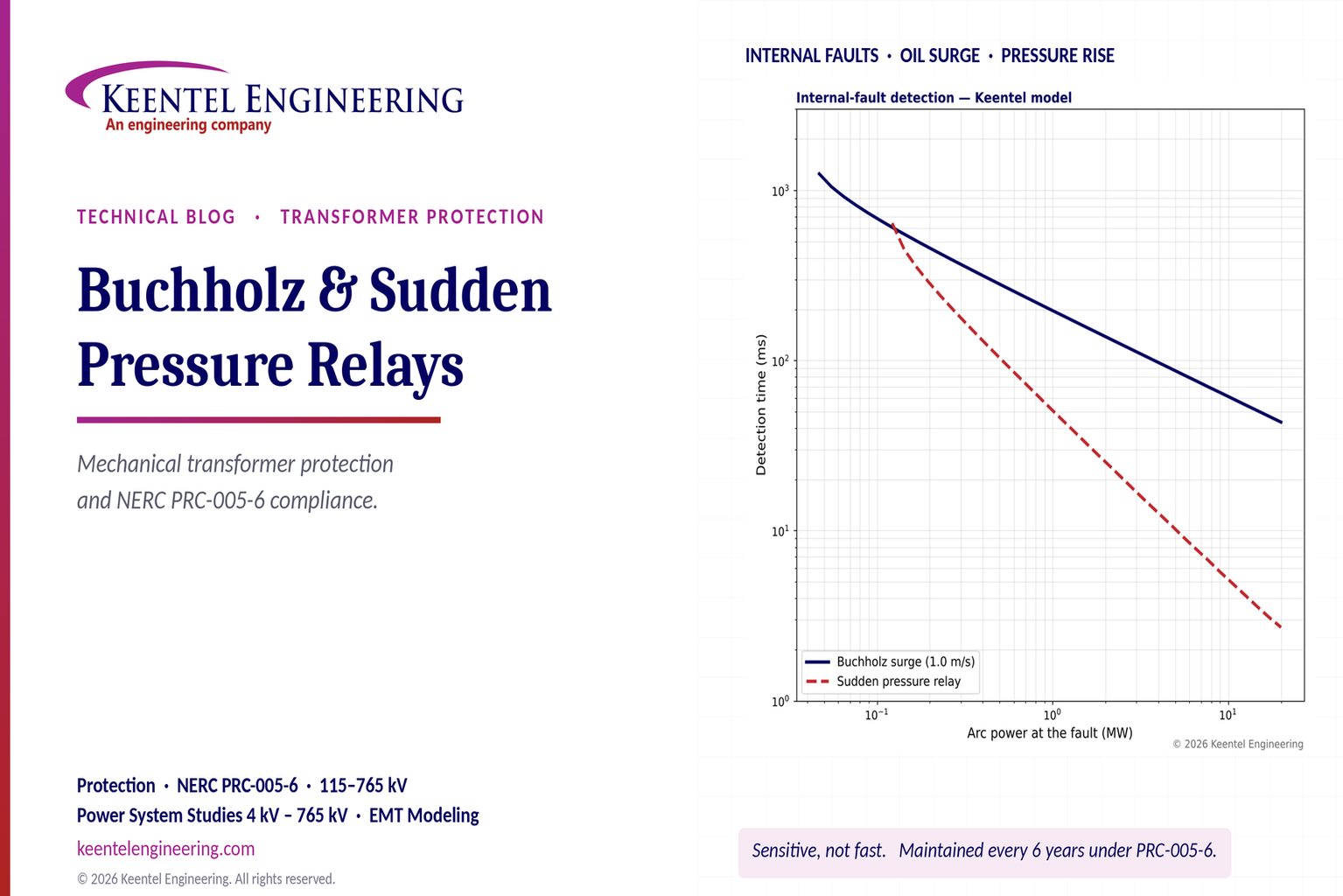
Learn how Buchholz and sudden pressure relays protect transformers, detect internal faults, and meet NERC PRC-005-6 maintenance requirements.
October 24, 2026
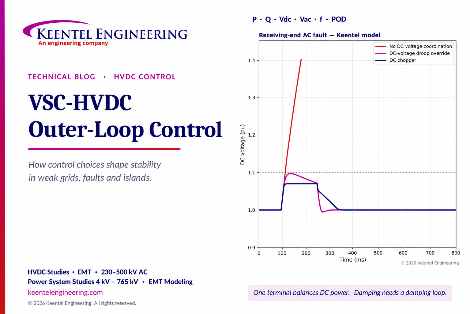
Explore VSC-HVDC outer-loop control for P, Q, DC voltage, weak-grid stability, fault ride-through and power oscillation damping with engineering models.
By SANDIP R PATEL
•
October 23, 2026
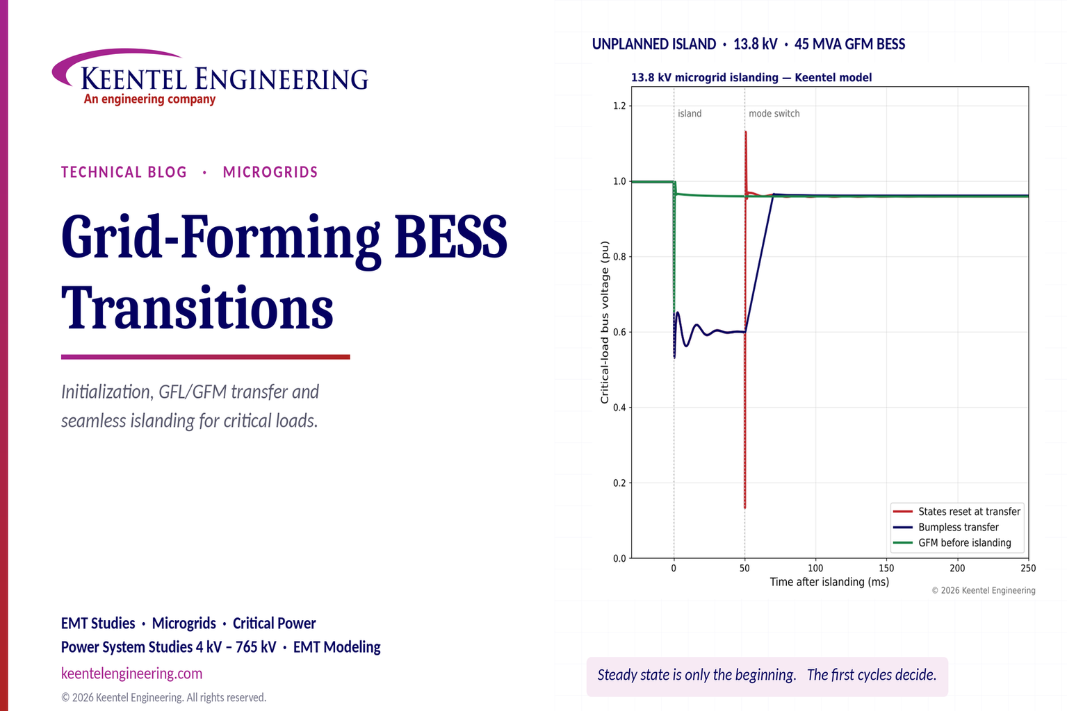
Explore grid-forming BESS initialization, GFL-to-GFM transitions, seamless islanding, EMT simulations, current limiting and microgrid protection.
By SANDIP R PATEL
•
October 23, 2026
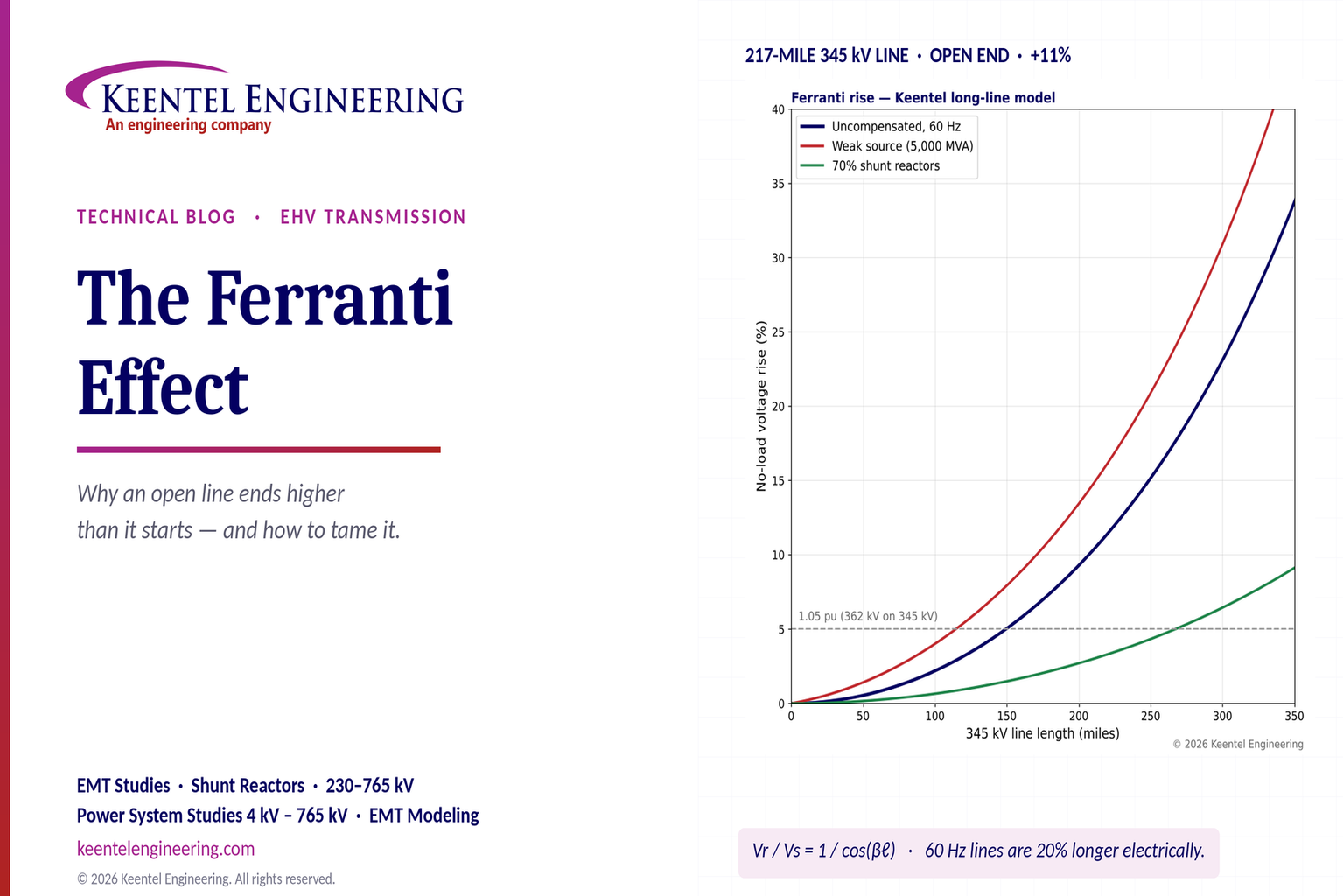
Explore the Ferranti effect in EHV transmission lines: voltage rise, 345 kV examples, switching overvoltages, shunt reactor sizing and mitigation.
By SANDIP R PATEL
•
October 23, 2026
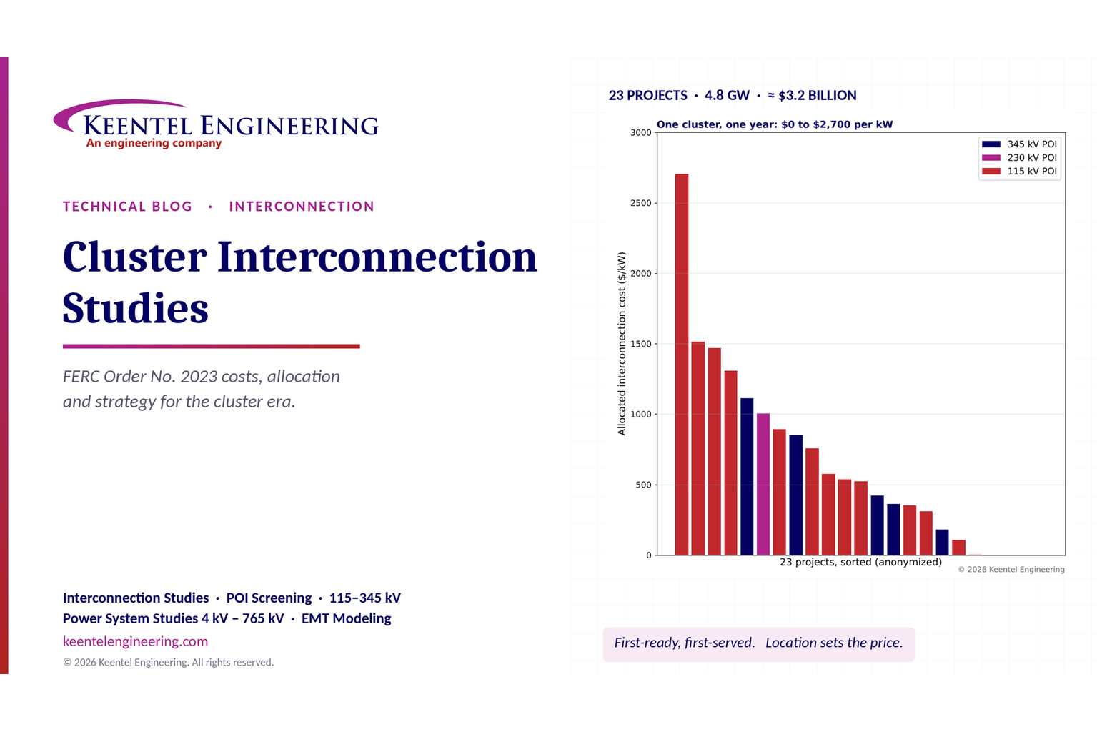
Explore cluster interconnection studies under FERC Order 2023, including network upgrades, cost allocation, withdrawal penalties and developer strategy.
By SANDIP R PATEL
•
October 21, 2026
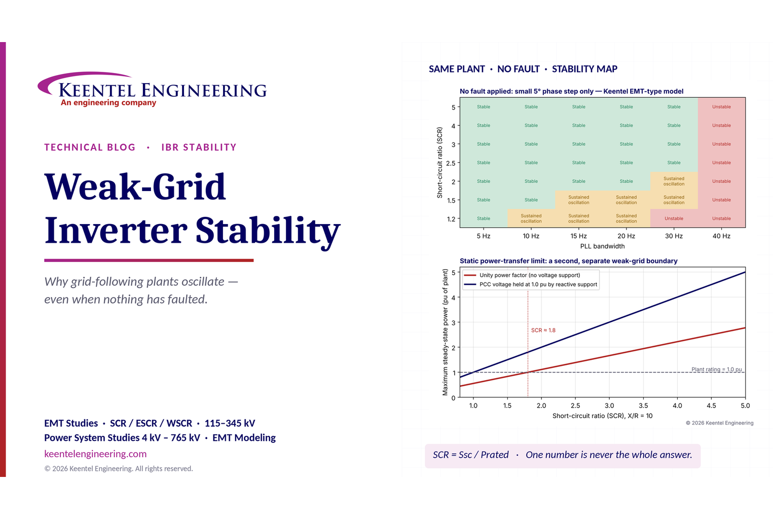
Learn why grid-following inverters become unstable without grid faults. Explore SCR, PLL interactions, EMT studies, grid strength, and mitigation.
By SANDIP R PATEL
•
October 21, 2026
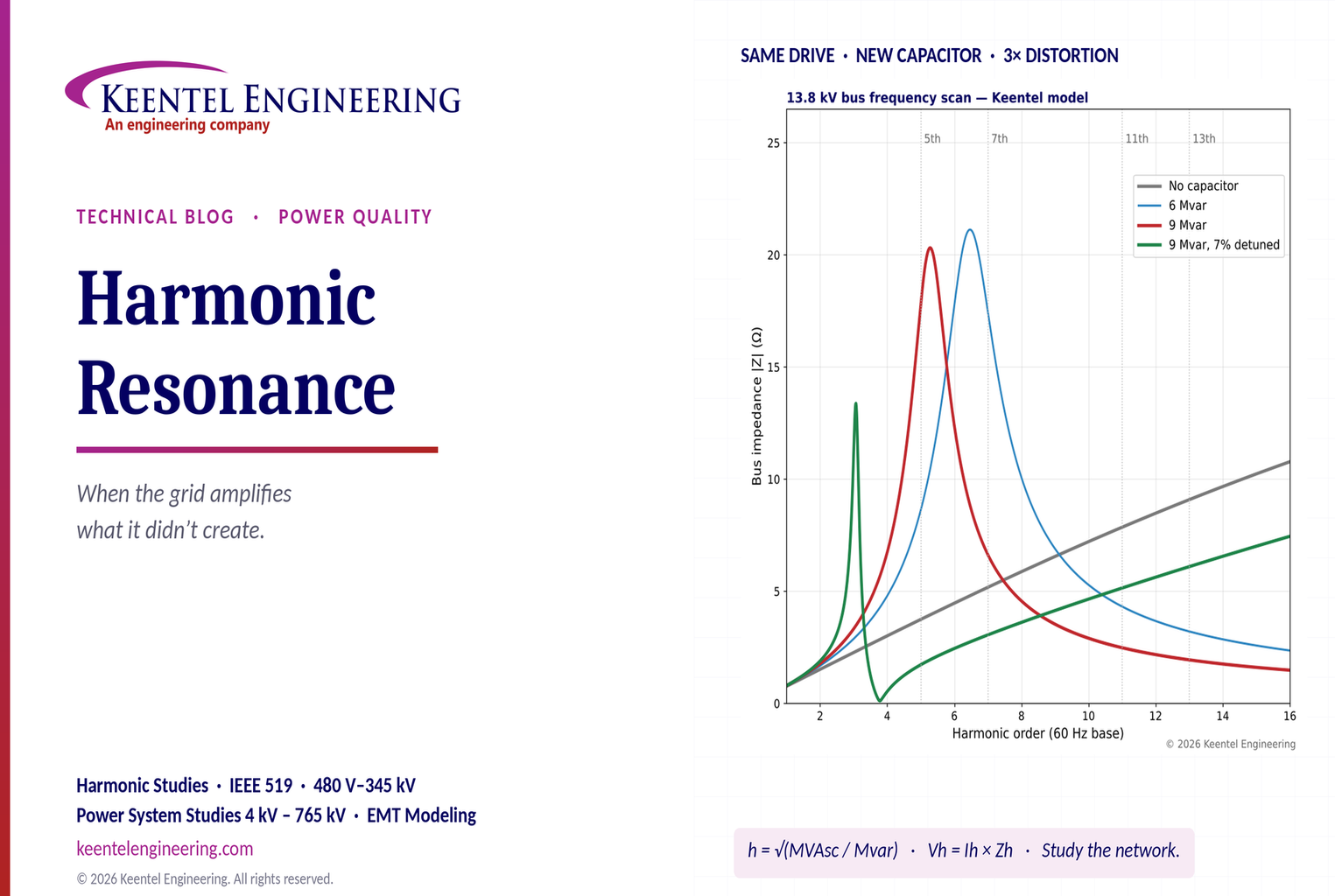
Learn how harmonic resonance amplifies distortion in power systems. Explore capacitor banks, detuned reactors, frequency scans, and IEEE 519 solutions.
By SANDIP R PATEL
•
October 20, 2026
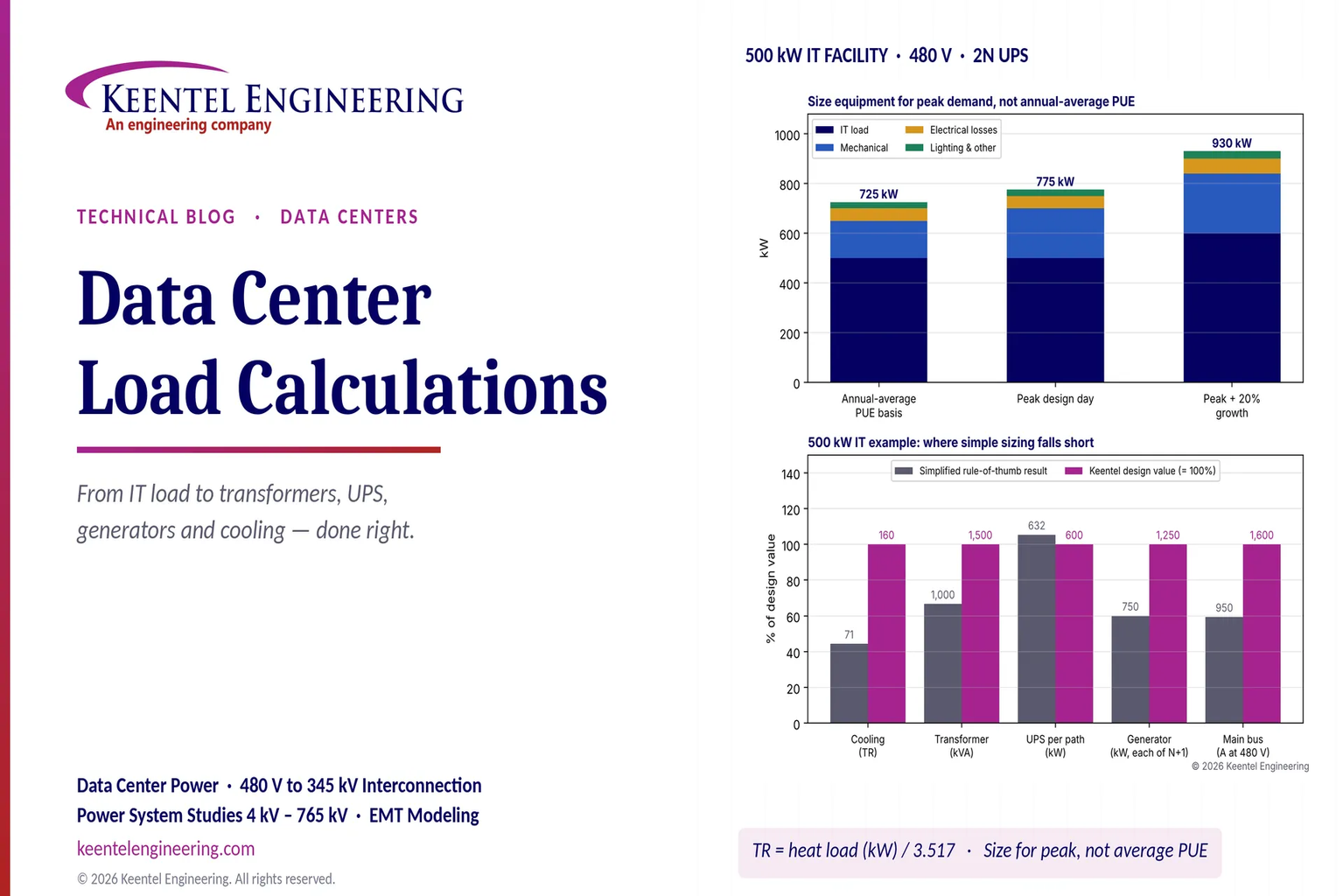
Learn data center electrical load calculations, including IT demand, PUE, UPS and generator sizing, cooling loads, redundancy, and worked US examples.
By SANDIP R PATEL
•
October 20, 2026
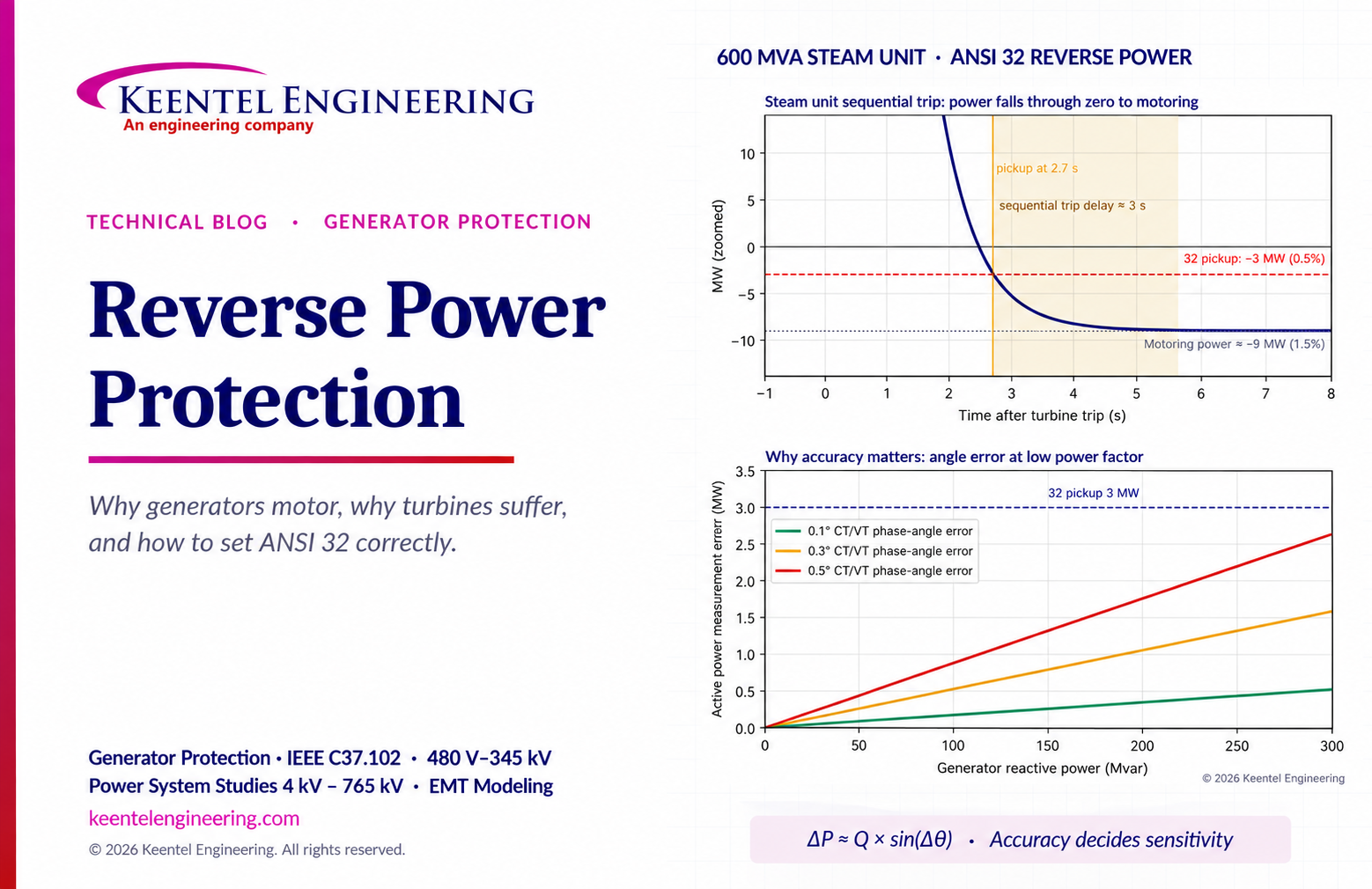
Learn reverse power protection (ANSI 32), generator motoring, relay pickup settings, time delays, sequential tripping and testing for US power plants.