
A Coordinated Electric System Interconnection Review—the utility’s deep-dive on technical and cost impacts of your project.
Challenge: Frequent false tripping using conventional electromechanical relays
Solution: SEL-487E integration with multi-terminal differential protection and dynamic inrush restraint
Result: 90% reduction in false trips, saving over $250,000 in downtime
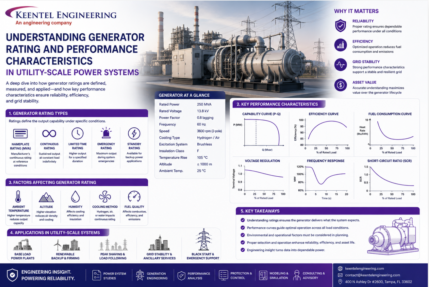
Understanding Generator Rating and Performance Characteristics in Utility-Scale Power Systems
May 25, 2026 | Blog
A Complete Technical Guide for Utility, Industrial, and Renewable Power Applications
Large synchronous generators are the backbone of modern power systems. Whether installed in thermal plants, hydroelectric stations, combined-cycle facilities, nuclear stations, or renewable energy plants with synchronous condensers, generator performance directly affects system reliability, grid stability, protection coordination, and long-term asset life.
For utility operators, EPC firms, independent power producers, and industrial facilities, understanding generator rating parameters is not simply an academic exercise—it is essential for safe operation, compliance, equipment specification, and system planning.
The uploaded reference document explains twelve essential parameters used in large generator ratings and operation. Keentel Engineering expands upon these concepts in this technical guide with practical engineering applications, protection implications, operational considerations, and grid integration insights.
Why Generator Rating Parameters Matter
Generator ratings define:
- Continuous operating capability
- Thermal limits
- Mechanical stress limits
- Electrical insulation capability
- Reactive power capability
- Grid support performance
- Stability characteristics
- Protection coordination requirements
Incorrect interpretation of these parameters can lead to:
- Rotor overheating
- Stator insulation failure
- Core damage
- Synchronization failures
- Grid instability
- Generator trips
- Reduced asset life
- Catastrophic failures
Modern generators are now reaching capacities above 1700 MVA in steam turbine applications and up to 400–500 MVA in gas turbine systems. As ratings increase, operational margins become tighter, making accurate engineering analysis even more critical.
The 12 Essential Generator Rating Parameters
1. Apparent Power (MVA Rating)
The apparent power rating is the primary parameter used to classify a generator. It represents the generator’s total electrical output capability and is normally expressed in MVA.
In three-phase systems:
MVA=3VLLIL
Where:
- VLL= line-to-line voltage
- IL= line current
The article explains that generator physical size is largely determined by voltage and current product rather than only real power.
Engineering Significance
MVA rating impacts:
- Bus duct sizing
- Generator transformer sizing
- Circuit breaker interrupting capacity
- Cooling system design
- Protection relay settings
- Short-circuit calculations
Keentel Engineering Perspective
In renewable and utility interconnection projects, improper MVA assumptions frequently result in:
- Under-rated collector systems
- Thermal overload conditions
- Incorrect relay coordination
- Interconnection study failures
Keentel Engineering performs detailed
load flow and thermal capability studies to validate generator MVA operation under normal and contingency conditions.
2. Real Power (MW Rating)
Real power is the actual usable electrical power delivered to the system.
The document states:
Rated MW output equals apparent power multiplied by power factor.
The relationship is:
MW=MVA×Power Factor
Why MW Rating Matters
MW rating determines:
- Turbine loading
- Fuel consumption
- Economic dispatch
- Grid scheduling
- Market participation
- Revenue generation
Operational Risks
The reference document emphasizes that MW overload conditions are extremely serious because they generally indicate stator current overload.
Excessive MW loading may cause:
- Stator winding overheating
- Core heating
- Insulation degradation
- Differential protection operation
- Generator trips
Practical Engineering Application
Keentel Engineering routinely evaluates:
- Generator overload capability
- Emergency loading conditions
- Thermal aging impacts
- Dynamic loading during contingencies
- NERC compliance implications
3. Power Factor (PF)
Power factor defines the phase angle relationship between voltage and current. The document explains that lagging power factor indicates VAR generation while leading power factor indicates VAR absorption.
Generator Operating Modes
Overexcited Generator
- Supplies reactive power (MVARs)
- Supports system voltage
- Operates in lagging PF region
Underexcited Generator
- Absorbs reactive power
- Reduces voltage
- Operates in leading PF region
The document notes that most large turbogenerators operate around 0.85–0.90 lagging PF.
Grid Stability Impacts
Reactive power directly influences:
- Voltage stability
- Transmission capability
- Oscillation damping
- Dynamic stability
- Fault recovery performance
Modern Grid Challenges
Today’s grids with inverter-based resources require stronger reactive support capabilities.
Keentel Engineering performs:
- Reactive capability studies
- Voltage stability analysis
- PV/PQ capability validation
- Dynamic reactive reserve assessment
- ERCOT and WECC interconnection support
4. Terminal Voltage
Terminal voltage is the continuous operating line-to-line voltage of the generator. The document states typical large generator voltages range from 13.8 kV to 27 kV.
Voltage Tolerance
IEEE-compliant generators generally operate continuously within ±5% of rated voltage.
Synchronization Requirements
Before breaker closure:
- Voltage magnitude must match
- Frequency must match
- Phase angle must match
Failure to synchronize correctly can produce:
- Severe shaft torque
- Rotor damage
- Pole slipping
- Generator transformer damage
Engineering Services by Keentel
Keentel Engineering supports:
- Synchronization studies
- Generator breaker coordination
- Voltage regulation design
- AVR tuning
- Excitation system integration
5. Stator Current
Stator current capability is one of the most critical thermal limitations of a generator.
The document explains that cooling method heavily influences stator current capability.
Cooling Types
Air-Cooled Generators
- Lower ratings
- Simpler maintenance
- Lower efficiency
Hydrogen-Cooled Generators
- Improved thermal performance
- Reduced windage losses
- Higher current capability
Water-Cooled Stator Systems
- Highest cooling effectiveness
- Common in very large units
Thermal Constraints
High stator current causes:
- Copper losses
- Insulation stress
- End-winding heating
- Core heating
The capability curve shown in the document demonstrates how hydrogen pressure affects generator capability.
Keentel Engineering Applications
Our engineers perform:
- Thermal capability assessments
- Generator uprating evaluations
- Cooling system review
- Loadability studies
- Generator protection coordination
6. Field Voltage
Field voltage controls rotor excitation.
The document states that increasing field voltage increases field current proportionally according to rotor resistance.
Why Field Voltage Matters
Field voltage impacts:
- Reactive power output
- Voltage regulation
- Stability response
- Excitation control
Common Failure Modes
AVR malfunctions may cause:
- Overexcitation
- Rotor overheating
- Excessive VAR export
- Loss of synchronism
Keentel Engineering evaluates excitation system performance through detailed transient stability studies and dynamic modeling.
7. Field Current
Field current determines rotor magnetic flux and generator excitation capability.
The document explains that increased field current:
- Increases MVAR export
- Raises stator current
- Increases terminal voltage potential difference
Engineering Importance
Field current affects:
- Rotor thermal limits
- Stability margins
- Voltage control
- Reactive capability
Protection Considerations
Protection systems monitor:
- Overexcitation
- Loss of excitation
- Rotor overheating
- Pole slipping
- V/Hz conditions
Keentel Engineering develops generator protection philosophies compliant with IEEE, NERC, ERCOT, and utility requirements.
8. Speed
Synchronous generators operate at fixed speed according to system frequency and pole count.
The document provides the equation:
Ns=120fP
Where:
- Ns= synchronous speed
- f= system frequency
- P= number of poles
Common Operating Speeds
60 Hz Systems
- 2-pole: 3600 rpm
- 4-pole: 1800 rpm
50 Hz Systems
- 2-pole: 3000 rpm
- 4-pole: 1500 rpm
Mechanical Implications
Higher speeds produce:
- Greater centrifugal stress
- Rotor vibration challenges
- Tighter balancing tolerances
Keentel Engineering performs torsional interaction studies and vibration risk assessments for generator-turbine systems.
9. Hydrogen Pressure
Hydrogen cooling dramatically improves generator efficiency and thermal capability.
The document notes that modern generators may operate up to 75 psig hydrogen pressure.
Advantages of Hydrogen Cooling
- Better heat transfer
- Lower windage losses
- Reduced oxidation
- Higher efficiency
- Increased MVA capability
Operational Risks
Hydrogen systems require careful monitoring because:
- Hydrogen leakage creates explosion hazards
- Pressure drops reduce cooling effectiveness
- Seal oil systems are critical
Engineering Focus Areas
Keentel Engineering evaluates:
- Hydrogen cooling system integration
- Alarm/trip settings
- Thermal performance
- Ventilation coordination
- Safety compliance
10. Hydrogen Temperature
Hydrogen gas temperature directly affects generator cooling performance.
The document explains:
- Typical cold gas temperatures: 30–40°C
- Maximum cold gas temperature: 46°C
- Typical hot/cold differential: 15–25°C
Why Temperature Control Matters
Poor cooling performance may cause:
- Rotor overheating
- Stator insulation damage
- Core hot spots
- Reduced generator life
Monitoring Systems
Generators commonly use:
- RTDs
- Thermocouples
- Cooler flow monitoring
- Alarm thresholds
Keentel Engineering assists clients with:
- Cooling optimization
- Thermal monitoring integration
- Generator condition assessment
- Predictive maintenance programs
11. Short-Circuit Ratio (SCR)
The short-circuit ratio is one of the most important indicators of generator stability performance.
The document defines SCR as the ratio between:
- Field current needed for rated voltage on open circuit
- Field current required for rated current during sustained short circuit
Why SCR Is Important
Higher SCR generally means:
- Better voltage regulation
- Improved transient stability
- Lower sensitivity to load changes
However, higher SCR may also:
- Increase generator size
- Reduce efficiency
- Increase cost
The document notes that modern turbine generators typically have SCR values between 0.4 and 0.6.
Modern Grid Challenges
Low-SCR systems are becoming increasingly common due to inverter-based resources.
Keentel Engineering specializes in:
- Weak-grid analysis
- Short-circuit ratio studies
- Grid-forming evaluations
- IBR stability assessment
- PSCAD and EMT simulations
12. Volts per Hertz (V/Hz) and Overfluxing
Overfluxing is among the most dangerous abnormal operating conditions for generators and transformers.
The document explains that flux density is proportional to V/Hz.
B∝Vf
What Happens During Overfluxing
Excessive V/Hz causes:
- Core saturation
- High magnetizing current
- Increased hysteresis losses
- Severe heating
The document warns that severe overfluxing can destroy core insulation and winding insulation within seconds.
Typical Causes
- AVR malfunction
- Load rejection
- Underfrequency conditions
- Incorrect transformer tap settings
- Black-start operations
Protection Systems
Modern generators include:
- ANSI 24 overexcitation protection
- V/Hz relays
- Temperature monitoring
- Core flux monitoring
Keentel Engineering provides:
- Protection setting development
- Generator relay coordination
- Dynamic event analysis
- Root-cause investigations
Generator Capability Curves and Operating Limits
The capability curve shown in the document illustrates the operational boundaries imposed by:
- Stator heating
- Rotor heating
- Core heating
- Stability limits
Understanding capability curves is critical for:
- Dispatch optimization
- Voltage support
- Reactive reserve planning
- Emergency operation
- Renewable integration
Keentel Engineering Generator Services
Keentel Engineering provides comprehensive generator engineering services including:
Generator Studies
- Load flow analysis
- Short-circuit analysis
- Dynamic stability studies
- Harmonic analysis
- EMT studies
Generator Protection
- Relay coordination
- Differential protection
- Out-of-step protection
- Overexcitation protection
- Loss-of-field protection
Generator Design Support
- Generator interconnection
- Excitation system design
- Synchronization systems
- Cooling system review
- Grounding analysis
Renewable Integration
- Weak-grid analysis
- IBR compliance
- NERC modeling support
- PSCAD simulations
- ERCOT and WECC compliance
Conclusion
Large generator ratings are far more than simple nameplate values. They represent the thermal, electrical, mechanical, and stability boundaries within which a generator must safely operate.
The twelve essential parameters discussed in this guide collectively define:
- Generator reliability
- Grid stability contribution
- Thermal operating limits
- Protection coordination
- Long-term equipment health
As modern power systems evolve toward higher renewable penetration and increasingly dynamic operating conditions, understanding these generator parameters becomes even more important.
Keentel Engineering helps utilities, renewable developers, industrial facilities, and independent power producers optimize generator performance, maintain compliance, and improve system reliability through advanced power system engineering and protection expertise.
Frequently Asked Questions (FAQs)
1. What is the difference between MW and MVA in generators?
MW represents real usable power, while MVA represents total apparent power including reactive power.
2. Why are generators rated in MVA instead of MW?
Because generator heating depends primarily on voltage and current rather than only real power output.
3. What causes generator overheating?
Common causes include:
Excessive stator current
Overexcitation
Cooling system failure
Poor hydrogen pressure
High V/Hz operation
4. What is reactive power in generators?
Reactive power (MVAR) supports voltage regulation and system stability but does not perform real work.
5. What does overexcited operation mean?
It means the generator is supplying reactive power to the grid.
6. What does underexcited operation mean?
It means the generator is absorbing reactive power from the grid.
7. Why is hydrogen used for cooling large generators?
Hydrogen has excellent thermal conductivity and low density, reducing losses and improving cooling.
8. What is generator synchronization?
Synchronization ensures voltage magnitude, frequency, and phase angle match the grid before breaker closure.
9. What is a capability curve?
A capability curve defines the safe operating limits of a generator in MW/MVAR space.
10. What is short-circuit ratio (SCR)?
SCR measures generator stability and excitation sensitivity characteristics.
11. Why is low SCR a concern?
Low SCR systems are weaker and more susceptible to voltage instability and oscillations.
12. What is V/Hz protection?
V/Hz protection prevents excessive magnetic flux that can damage generator cores and windings.
13. What happens during overfluxing?
Core saturation occurs, producing excessive heating and insulation stress.
14. What is the purpose of an AVR?
The Automatic Voltage Regulator controls generator excitation and terminal voltage.
15. What protection relays are commonly used for generators?
Typical protections include:
Differential protection (87G)
Loss of field (40)
Overexcitation (24)
Reverse power (32)
Negative sequence (46)
16. Why is stator current critical?
Excessive stator current directly causes copper losses and winding overheating.
17. How does frequency affect generator speed?
Synchronous speed is directly proportional to system frequency.
18. What is unity power factor?
Unity power factor means voltage and current are perfectly aligned.
19. Why are hydrogen temperatures monitored?
To ensure proper generator cooling and prevent insulation damage.
20. How does Keentel Engineering support generator projects?
Keentel Engineering provides:
- Power system studies
- Generator protection design
- Dynamic modeling
- Renewable integration analysis
- NERC compliance support
- Interconnection engineering

About the Author:
Sonny Patel P.E. EC
IEEE Senior Member
In 1995, Sandip (Sonny) R. Patel earned his Electrical Engineering degree from the University of Illinois, specializing in Electrical Engineering . But degrees don’t build legacies—action does. For three decades, he’s been shaping the future of engineering, not just as a licensed Professional Engineer across multiple states (Florida, California, New York, West Virginia, and Minnesota), but as a doer. A builder. A leader. Not just an engineer. A Licensed Electrical Contractor in Florida with an Unlimited EC license. Not just an executive. The founder and CEO of KEENTEL LLC—where expertise meets execution. Three decades. Multiple states. Endless impact.
Services

Let's Discuss Your Project
Let's book a call to discuss your electrical engineering project that we can help you with.
About the Author:
Sonny Patel P.E. EC
IEEE Senior Member
In 1995, Sandip (Sonny) R. Patel earned his Electrical Engineering degree from the University of Illinois, specializing in Electrical Engineering . But degrees don’t build legacies—action does. For three decades, he’s been shaping the future of engineering, not just as a licensed Professional Engineer across multiple states (Florida, California, New York, West Virginia, and Minnesota), but as a doer. A builder. A leader. Not just an engineer. A Licensed Electrical Contractor in Florida with an Unlimited EC license. Not just an executive. The founder and CEO of KEENTEL LLC—where expertise meets execution. Three decades. Multiple states. Endless impact.
Leave a Comment
Thank you for contacting us.
We will get back to you as soon as possible.
We will get back to you as soon as possible.
Oops, there was an error sending your message.
Please try again later.
Please try again later.
Related Posts
By SANDIP R PATEL
•
July 15, 2026
Learn how PJM markets, governance, stakeholder processes, and interconnection rules shape generation, storage, and large-load projects across North America.
By SANDIP R PATEL
•
July 14, 2026
Learn how AI data centers, cryptocurrency mining, and hydrogen electrolysis impact grid interconnection, EMT modeling, power quality, and system reliability.

By SANDIP R PATEL
•
July 13, 2026
Learn the complete ERCOT BESS interconnection process for TNMP and AEP Texas, including GINR, studies, SGIA, commissioning, fees, and project timelines.
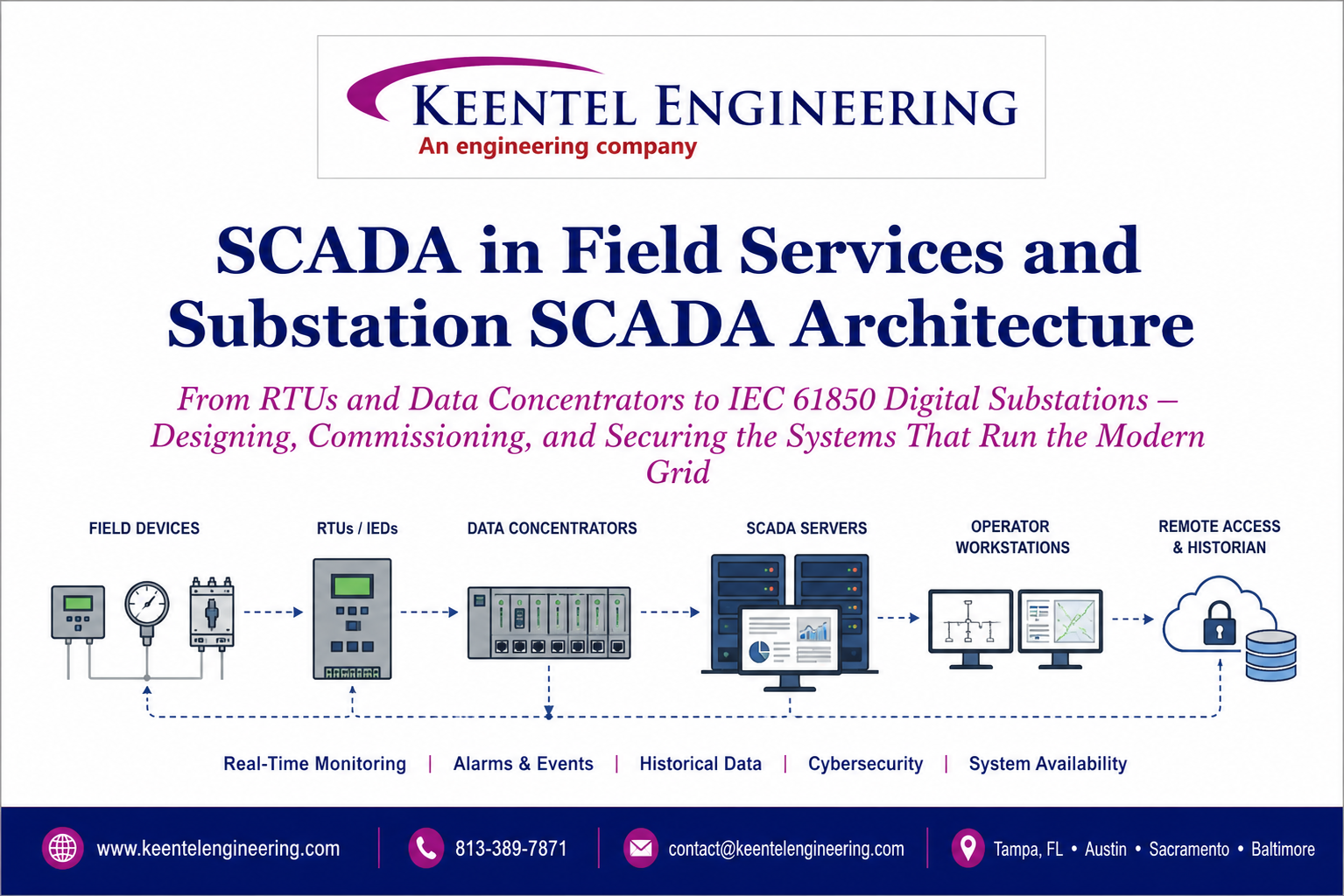
By SANDIP R PATEL
•
July 13, 2026
Learn SCADA architecture, IEC 61850, RTUs, IEDs, DNP3, digital substations, commissioning, cybersecurity, and field services for modern power systems.

By SANDIP R PATEL
•
July 13, 2026
Learn how IEEE standards for grounding, protection, power quality, arc flash, and grid interconnection are applied in real engineering projects.
By SANDIP R PATEL
•
July 12, 2026
Complete PRC-028-1 guide for inverter-based resources. 12-chapter technical resource
By SANDIP R PATEL
•
July 11, 2026
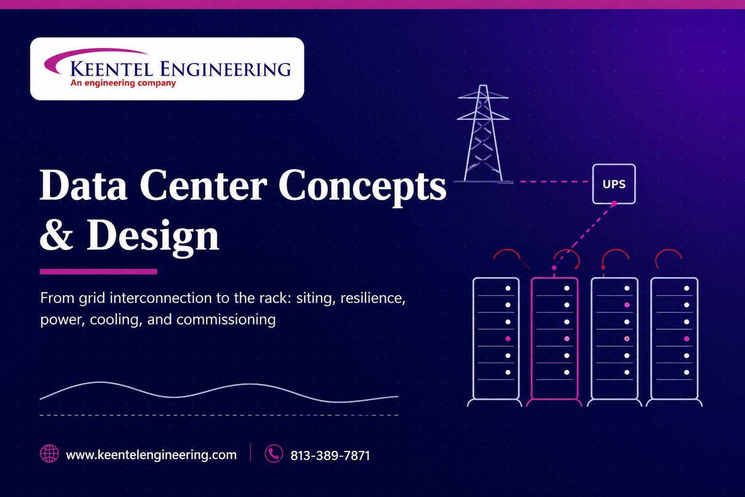
Learn modern data center design, grid interconnection, electrical systems, cooling, commissioning, resilience, and operations for AI-ready facilities.

By SANDIP R PATEL
•
July 11, 2026
Master IEC 61850 SCADA engineering with ACSELERATOR Architect, GOOSE messaging, MMS, SCL files, server models, commissioning, and substation automation.
By SANDIP R PATEL
•
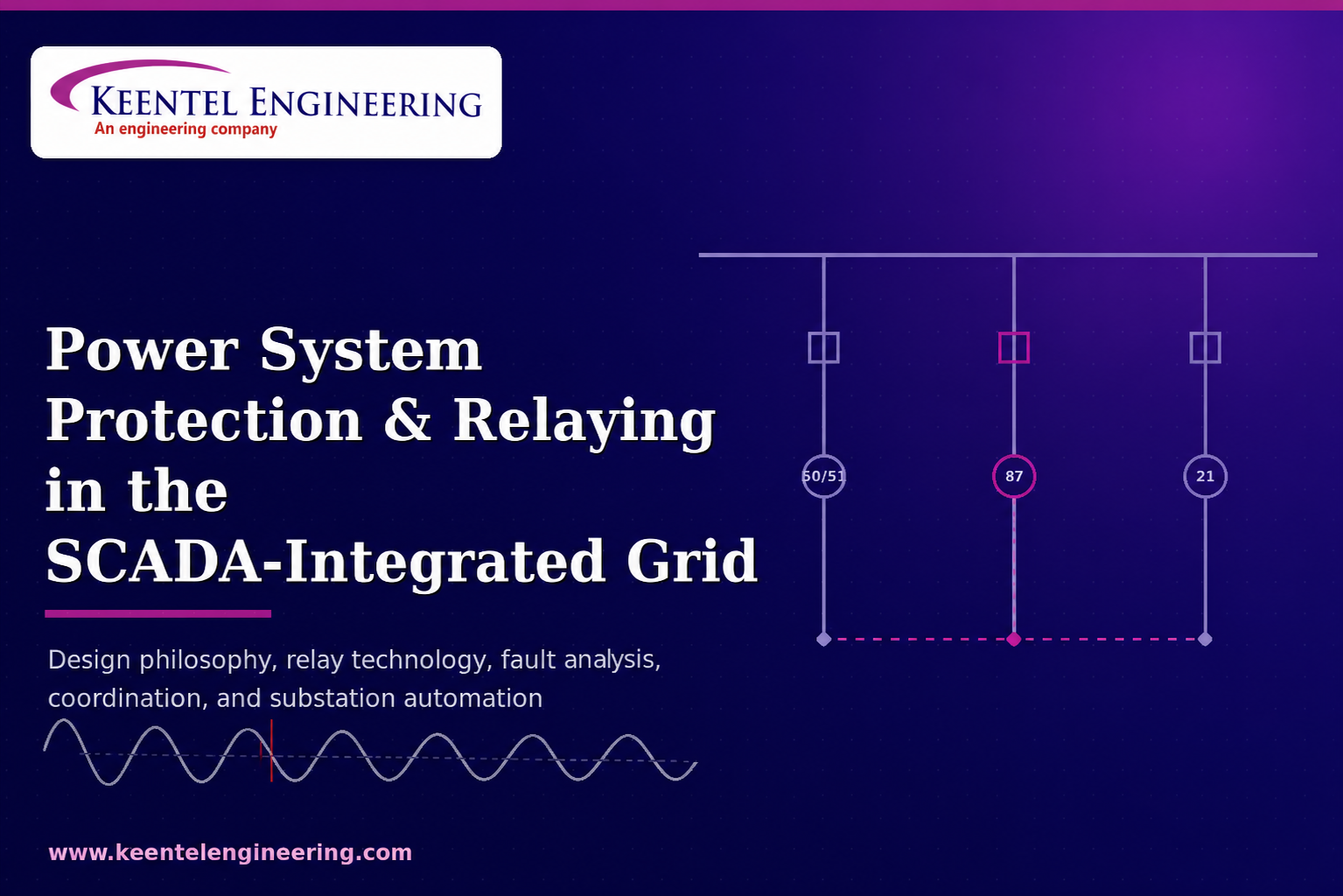
July 11, 2026
Learn power system protection and relaying, SCADA integration, relay coordination, fault analysis, grounding, and substation protection engineering.


