
A Coordinated Electric System Interconnection Review—the utility’s deep-dive on technical and cost impacts of your project.
Challenge: Frequent false tripping using conventional electromechanical relays
Solution: SEL-487E integration with multi-terminal differential protection and dynamic inrush restraint
Result: 90% reduction in false trips, saving over $250,000 in downtime
ERCOT enforces all of the above through simulation, which means your model is your compliance case. The bar is now high:
- Whole-facility scope. The model must represent everything the IT load, the UPS and power conversion, the cooling plant, the protection and control systems in formats compatible with ERCOT's study platforms (PSS/E, PSCAD, TSAT).
- Real control loops, not approximations. Generic textbook representations are unacceptable. The model must capture the actual inner control behavior of your power electronics.
- Hardware-validated converter models. For electronic loads, the PSCAD model must be benchmarked against actual hardware testing including voltage ride-through and subsynchronous response. A model assembled from standard PSCAD library blocks fails by definition, because a generic block has never been tested against your vendor's hardware. The good news: validation is a hardware-type test, so results for a given converter product are reusable across every facility that uses it.
- Format migration. Facilities that previously submitted the older composite load model (CMLD) format must transition to EPRI's PERC1 format.
- Three checkpoints. Models are reviewed before the stability study begins (no model, no study), before each quarterly stability assessment, and for electronic loads one final time before energization, when you must submit as-built models with a documented comparison against the previously studied data and a sworn attestation that the model matches actual field settings. ERCOT's review takes 10 business days, extendable by 20 put it on your critical path.
- A living obligation. Change your technology, controls, or relay settings in a way that affects ride-through including converting a crypto mining site to an AI data center — and you've triggered a new interconnection study, even if your megawatts don't change.
| Parameter | Detail |
|---|---|
| System | 230 kV / 138 kV transmission corridors, wind and wet-snow icing exposure |
| Data basis | 15 years of minute-resolution forced-outage records + regional weather observations |
| Core methods | Event grouping, MVA performance curves, time-to-95%-restore, area outage rate curves, fragility modeling, rerun-history benefits, exceedance and log-domain risk metrics |
| Headline result | ≈85% of maximum resilience benefit at 60% of original capital; worst-event restoration window cut from 11 days to 5 in rerun-history terms |
| Decision supported | Capital portfolio selection; resilience plan filing; post-investment verification framework |
| System / Topic | Governing Standard(s) | What It Controls |
|---|---|---|
| Overall plant electrical distribution | IEEE 141 (Red Book); IEEE 666 | Distribution architecture, voltage selection, design of generating station auxiliary service systems |
| Power system studies | IEEE 399 (Brown Book); IEEE 551 | Load flow, symmetrical/asymmetrical short circuit, motor starting methodologies down to the lowest LV panelboard |
| Protection & coordination | IEEE 242 (Buff Book); IEEE 3004.5; IEEE C37 series | Generator relaying (21, 59N, 87G), time-current coordination, selective clearing between LV and MV tiers |
| GSU / UAT / SST transformers | IEEE C57.12.00 and C57 family | Transformer ratings, impedance, testing, loading |
| HV switchyard breakers | IEEE C37.06 | AC high-voltage circuit breaker preferred ratings |
| MV switchgear (13.8 kV) | IEEE C37.20.2; IEEE C37.20.7 | Metal-clad construction, compartmentalization, vacuum breakers; arc-resistant design with plenum venting |
| MV cable | UL 1072; ICEA S-93-639 (NEMA WC 74) | Type MV-105 shielded cable, 133% insulation level for HRG systems |
| LV switchgear (480 V) | IEEE C37.13; UL 1558 | Metal-enclosed LV power circuit breaker switchgear to 635 V, draw-out ACBs with electronic trip units |
| Motor control centers | UL 845; NEMA ICS 18 | LV-MCC construction, MCCB/MCP protection for motors under ~200 HP |
| Motors | NEMA MG-1 | Motor performance, starting characteristics, service factors |
| DC & battery systems | IEEE 485; IEEE 946 | Lead-acid battery sizing (125/250 VDC), DC auxiliary system design |
| Grounding | IEEE 80; IEEE 142 (Green Book) | Ground grid step/touch potential limits; system grounding including high-resistance grounding |
| Lightning protection | IEEE 998 | Direct-stroke shielding of switchyard and outdoor generator structures |
| Arc flash & electrical safety | IEEE 1584; NFPA 70E | Incident energy calculation; worker safety boundaries and PPE |
| Fire protection | NFPA 850 | Fire protection and risk management for combustion turbine generating plants |
| Installation code | NEC (NFPA 70); NESC | Wiring methods inside the plant fence; overhead/outdoor clearances at the switchyard |
| Interconnection & compliance | FERC LGIP; NERC MOD-025/026/027, PRC-019/024/029, FAC-008 | Interconnection process, model validation, protection/ride-through coordination, facility ratings |
| IFC / Construction Deliverable | Purpose |
|---|---|
| Stamped IFC packages | Legal basis for construction; P.E. responsible charge |
| Final relay settings & TCCs | Protection as-installed matches the coordination study |
| Calculation archive | Owner records; NERC audit evidence trail |
| Commissioning procedures | Safe, sequenced energization; MOD field testing |
| Construction support | RFIs, field changes, FAT/SAT witness |
| As-builts & model handoff | Operating baseline; future study currency |
| Metric | Outcome |
|---|---|
| Defects found pre-occupancy | Three topology defects and one settings-mismatch family corrected before load migration; the shared-switchboard defect alone would have invalidated the concurrently-maintainable claim on day one |
| IST findings | Fourteen additional discrepancies surfaced under scenario testing (control logic, alarm mapping, one generator sequencing fault) — all closed before handover instead of during operations |
| Black-building test | Passed on second execution; the first attempt exposed the generator sequencing fault under true block load, exactly the failure the compressed plan would never have found |
| Handover quality | Operations team certified on the actual failure scenarios; corrected EOPs and settings documentation delivered as controlled documents |
| Business outcome | Occupancy proceeded three weeks behind the original date — against an independent estimate that the uncorrected sequencing fault carried a high probability of a full facility outage within the first year |
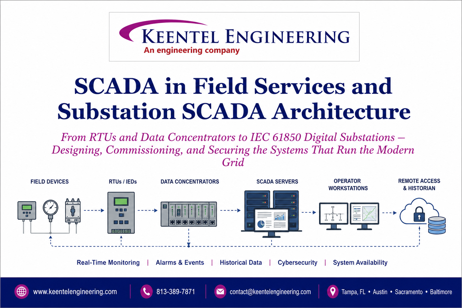
SCADA in Field Services and Substation SCADA Architecture
Jul 13, 2026 | Blog
From RTUs and Data Concentrators to IEC 61850 Digital Substations — Designing, Commissioning, and Securing the Systems That Run the Modern Grid
1. Why SCADA Is Now a First-Order Design Input
Supervisory Control and Data Acquisition has quietly become the nervous system of the North American grid. Every unmanned substation, every utility-scale solar plant, every battery energy storage facility, and every large-load interconnection depends on a SCADA architecture that acquires field data reliably, transports it securely, and presents it to operators in a form that supports fast, correct decisions. Yet on far too many projects, SCADA is still treated the way interconnection studies once were: as a late-stage administrative task, scoped after the one-line is frozen and the protection panels are ordered.
At Keentel Engineering, we take the opposite view. SCADA architecture — point counts, protocol selection, network topology, redundancy philosophy, and cybersecurity zoning — belongs at the 30% design milestone, alongside the protection and control philosophy. Retrofitting a communications architecture into a substation that was not designed for it is expensive; retrofitting cybersecurity into a SCADA system that was not zoned for it is worse. This blog walks through what SCADA actually does in the field, how modern substation SCADA architectures are structured, and where field-services engineering makes or breaks the outcome.
2. SCADA Fundamentals: Data Acquisition to Supervisory Control
At its core, every SCADA system performs the same loop: sense, digitize, transmit, interpret, decide, and act. Field sensors and instrument transformers measure analog quantities — voltages, currents, temperatures, pressures, tap positions. Signal conditioning and analog-to-digital conversion turn those measurements into digital values. Communication links move the data to a master station, where operators and applications interpret it, and control commands travel the same path in reverse to breakers, switches, tap changers, and inverter controllers.
SCADA has evolved through four recognizable generations. First-generation monolithic systems ran on standalone minicomputers with proprietary protocols and no external connectivity.
Second-generation distributed systems spread processing across networked stations on a LAN. Third-generation networked SCADA embraced open standards — DNP3, IEC 60870-5, and eventually IEC 61850 — allowing multi-vendor interoperability across wide-area networks. The fourth generation folds in IP-native architectures, cloud-adjacent analytics, and IIoT-style edge devices. Most utilities today operate somewhere between the third and fourth generation, with legacy islands from the first two still in service — which is exactly why field-services engineering and protocol integration remain so consequential.
Keentel Perspective
Generational mixing is the norm, not the exception. A typical brownfield substation we encounter has a 20-year-old RTU polling serial IEDs, a partially deployed station bus, and a corporate mandate to reach IEC 61850. The engineering challenge is not choosing the destination — it is sequencing the migration so protection, control, and NERC compliance never lapse along the way.
3. The Building Blocks: RTUs, IEDs, Data Concentrators, and Merging Units
3.1 Remote Terminal Units and Gateways
The RTU remains the workhorse of substation data acquisition. A modern RTU is a modular platform — CPU, analog input/output cards, digital status inputs, control outputs, redundant power supplies, and multiple communication interfaces — hardened for the substation environment and increasingly expected to carry NERC CIP-relevant security functions. Critically, the modern RTU is no longer just an I/O box: it acts as the substation data concentrator and secure gateway, polling dozens of IEDs over the station LAN, performing protocol conversion for legacy devices, hosting a web-based local HMI, and presenting a single hardened connection point to the wide-area network.
3.2 Intelligent Electronic Devices
Microprocessor-based protective relays, meters, bay controllers, and power-quality monitors — collectively IEDs — have absorbed functions that once required racks of discrete hardware. A single modern relay provides protection elements, metering, event and disturbance recording, breaker monitoring, and native Ethernet communications. From a SCADA architecture standpoint, IEDs are both the richest data sources in the substation and the devices whose configuration discipline most directly determines data quality at the master station.
3.3 Merging Units and the Process Bus
Merging units extend the digital architecture from the control house into the switchyard. By digitizing current and voltage signals at the primary equipment and publishing time-synchronized sampled values over fiber, the merging unit replaces bundles of copper CT and VT wiring with a process bus. The payoff is significant: reduced copper, reduced CT saturation and open-circuit hazards, simplified panel wiring, and a foundation for fully digital substations
The cost is a new engineering discipline — process bus network design, time synchronization (PTP/IEEE 1588), and sampled-value performance validation all become field-services responsibilities that did not exist in the copper world.
3.4 Master Stations and the HMI
At the top of the hierarchy sits the master control center: SCADA servers, application servers, historians, communication front ends, ICCP servers for inter-utility data exchange, network management, and dispatcher training simulators. The human-machine interface is where architecture meets operations — mimic diagrams, alarm handling, and situational-awareness tools determine whether an operator can distinguish a genuine cascading event from an alarm flood. Intelligent alarm filtering and rationalized alarm philosophies are design deliverables, not afterthoughts.
4. Substation SCADA Architecture: Levels, Buses, and Topologies
| Level | Equipment | Primary Functions | Key Networks / Protocols |
|---|---|---|---|
| Process Level | CTs/VTs, NCITs, merging units, breaker I/O, actuators | Signal acquisition and digitization at primary equipment | Process bus — IEC 61850-9-2 Sampled Values, GOOSE |
| Bay Level | Protective relays, bay controllers, meters | Protection, interlocking, local control, event recording | Station bus — IEC 61850 MMS, GOOSE peer-to-peer |
| Station Level | RTU/gateway, station HMI, engineering workstation, GPS clock | Data concentration, protocol conversion, local supervision, secure WAN gateway | DNP3 / IEC 60870-5-104 to control center; PTP/IRIG-B timing |
Above the station level, the utility control center connects via DNP3 (dominant in North America) or IEC 60870-5-104 (dominant internationally), while control centers exchange data with neighbors and reliability coordinators over ICCP (IEC 60870-6 / TASE.2). The architecture within the station can be arranged in several topologies — cascaded (daisy-chained) switches for small stations, ring architectures with rapid spanning tree for medium stations, and fully redundant designs using PRP (Parallel Redundancy Protocol) or HSR (High-availability Seamless Redundancy) where zero-recovery-time failover is required for protection-class traffic.
Design Rule of Thumb
Match the network redundancy class to the traffic class. Supervisory polling can tolerate seconds of network reconvergence; GOOSE-based breaker-failure tripping and sampled values cannot. If protection functions ride the network, the network is protection equipment — design, test, and maintain it to that standard.
5. Reliability Engineering: Fail-Safe, Fault-Tolerant, and High-Availability Design
Because SCADA directly supervises energized equipment, its reliability philosophy must be explicit. Three related but distinct concepts govern the design:
- Fail-safe — A design that, upon failure, defaults to a state that cannot cause harm — normally-closed alarm circuits that annunciate on wire break, complementary signal pairs that expose sensor faults, and control outputs that revert to safe states on loss of communication.
- Fault-tolerant — A design that continues full operation through component failure — duplexed CPUs, mirrored disks and historians, redundant power supplies, and hot-standby servers with automatic changeover.
- High availability — A design philosophy for the overall system — dual independent LANs, redundant communication channels and routes to the control center, primary/secondary master configurations, and geographically separated backup control centers.
In power system SCADA, redundancy must be traced end to end: a redundant server farm buys nothing if a single serial link, single antenna, or single station gateway sits in the path of critical data. Channel redundancy from the RTU outward, CPU and port redundancy in the RTU itself, dual station LANs, and diverse WAN routing are the recurring requirements for mission-critical points — and the items most frequently value-engineered out under budget pressure. Our position is straightforward: define the critical-function list first, apply full redundancy to that list without compromise, and economize elsewhere.
6. Protocols: Choosing and Integrating the Right Ones
Protocol selection shapes everything downstream — point mapping effort, event time-tagging fidelity, bandwidth requirements, and the cybersecurity surface. The table below summarizes the protocols a substation SCADA engineer in North America actually encounters:
| Protocol | Typical Role | Strengths | Watch Items |
|---|---|---|---|
| DNP3 / DNP3-SA | Substation-to-control-center telemetry (North America) | Event buffering, time-tagged SOE, unsolicited reporting, secure authentication option | Legacy deployments without authentication; inconsistent point mapping practices |
| IEC 60870-5-101/104 | Substation-to-control-center telemetry (international) | Mature, widely supported serial and TCP/IP profiles | Limited native security without IEC 62351 wrappers |
| Modbus RTU/TCP | Legacy IEDs, BOP devices, meters, inverters | Ubiquitous, simple, cheap to implement | No authentication, no time tags, no events — poll-only |
| IEC 61850 MMS | Station bus client/server data and control | Self-describing object models, engineering via SCL, vendor interoperability | Configuration discipline; version and edition mismatches |
| IEC 61850 GOOSE | Peer-to-peer protection signaling, interlocking | Millisecond multicast messaging replacing hardwired trip/interlock circuits | VLAN and network design; testing and isolation practices |
| IEC 61850-9-2 SV | Process bus sampled values from merging units | Digitized CT/VT signals over fiber; enables digital substations | Time-sync dependency (PTP); network performance validation |
| ICCP / TASE.2 | Control-center-to-control-center exchange | Standardized inter-utility and RC data sharing via bilateral tables | Implementation interoperability; association and table management |
legacy Modbus and serial DNP3 devices concentrated behind a gateway that normalizes them into the station data model;
IEC 61850 deployed for the station bus where it earns its complexity; and a clean, well-documented DNP3 or 104 point map presented to the control center. Complementary standards round out the picture — IEEE C37.118 for synchrophasor streams, IEC 62351 for protocol-layer security, and IEC 61968/61970 (CIM) for enterprise data integration.
7. SCADA in Field Services: Where Architecture Meets Reality
A SCADA architecture is only as good as its commissioning. Field services is where the design assumptions — point lists, protocol mappings, network settings, failover logic — are proven against energized reality. In our experience, the field scope breaks into six recurring disciplines:
- Point-to-point and end-to-end testing — Verifying every analog scale factor, every status point, and every control output from the field device through the RTU/gateway to the control center display. Point-to-point testing is tedious and non-negotiable; a mis-scaled MW point or reversed breaker status discovered during a system event is an operational hazard.
- Integration and protocol conversion — Configuring and validating protocol conversions at the gateway — Modbus registers to DNP3 points, serial IED data into the 61850 station model — including exception behaviors, quality flags, and time-tag propagation that only surface under fault and restart conditions.
- FAT and SAT — Structured factory acceptance testing against the approved point database and HMI screens, followed by site acceptance testing with the real field wiring, real communication channels, and real master station — with documented punch lists closing the loop between the two.
- Redundancy validation — Failover and redundancy proving: pulling primary power supplies, failing network links, forcing server changeovers, and confirming the system degrades and recovers exactly as the reliability philosophy promises — with no loss of event data and no spurious controls.
- Timing and SOE integrity — Time synchronization verification across GPS clocks, IRIG-B distribution, PTP grandmasters, and NTP fallbacks, so sequence-of-events records and synchrophasor data are trustworthy for post-event analysis and NERC disturbance-monitoring obligations.
- Migration and cutover — Cutover planning for brownfield migrations — sequencing legacy RTU retirement, parallel operation windows, rollback criteria, and outage coordination so the control center never loses visibility of an energized station.
Field Reality Check
The most common field finding is not a broken device — it is an undocumented assumption. A point list that drifted from the relay settings, a gateway map edited on-site without a database update, a spare input landed on the wrong terminal. Rigorous configuration management, disciplined as-built documentation, and independent point-to-point verification are the cheapest insurance a utility can buy.
8. Securing the Substation SCADA System
SCADA security differs fundamentally from enterprise IT security: availability and integrity outrank confidentiality, devices live for decades, and patching windows are constrained by outage schedules. The threat catalog is well established — false data injection, replay and covert attacks against control loops, protocol exploits against unauthenticated DNP3/Modbus, malicious firmware, and removable-media vectors into engineering workstations. History's marquee ICS malware families all exploited the same underlying gaps: flat networks, unauthenticated protocols, and unmanaged remote access.
The countermeasure framework is defense-in-depth, applied specifically to the substation context:
- Zone-based architecture — Segment the architecture into security zones with defined conduits: process bus, station bus, station-level DMZ, WAN, and control center — each boundary enforced by firewalls of differing makes with deny-by-default rulesets, and no direct sessions permitted from less-trusted zones into the SCADA core.
- ICS-aware monitoring — Deploy SCADA-aware intrusion detection that understands DNP3, 61850, and Modbus semantics — flagging not just malformed packets but valid-but-anomalous control sequences.
- Endpoint hardening — Harden the endpoints: RTU and IED account management, disabled unused ports and services, signed firmware, controlled removable media, and secured local HMI access.
- Protocol-layer security — Wrap the protocols: DNP3 Secure Authentication and IEC 62351 profiles where the installed base supports them; encrypted VPN transport for WAN links regardless.
- Compliance as architecture — Anchor the program in NERC CIP: asset categorization, electronic security perimeters, interactive remote access management, configuration change monitoring, and incident response — engineered into the architecture rather than bolted on for audit season.
9. The Migration Question: Legacy, Hybrid, or Fully Digital?
Very few utilities can justify rip-and-replace. The economically rational path is almost always hybrid: new IEDs, data concentrators, and fiber deployed on an expansion or protection-refresh project, coexisting with the legacy RTU-based system while protocol conversion bridges the two. The engineering discipline lies in defining the target architecture first — station bus topology, data model, security zones, naming conventions — so each incremental project is a step toward the target rather than another one-off island. For greenfield stations, the calculus increasingly favors going digital from the start: IEC 61850 station and process bus, merging units, PRP/HSR networking, and an HMI with modern situational awareness, specified as an integrated system rather than assembled by change order.
10. How Keentel Engineering Supports SCADA and Substation Automation
Keentel Engineering delivers substation SCADA and automation as an integrated engineering scope — not a bolt-on to someone else's design. Our services span:
- Architecture and design — SCADA architecture development and 30/60/90/IFC design integration for transmission and distribution substations, renewable plants, BESS facilities, and large-load interconnections.
- Integration engineering — RTAC/gateway configuration, IEC 61850 system engineering (SCL, GOOSE, sampled values), DNP3 and Modbus point mapping, and legacy protocol integration.
- Field services and commissioning — FAT/SAT planning and execution, point-to-point testing, redundancy and failover validation, and commissioning support through energization.
- Compliance and cybersecurity — NERC CIP-aligned network zoning, secure remote access design, and disturbance-monitoring compliance engineering for conventional and inverter-based resources.
- Owner's engineer services — Owner's engineer oversight of vendor SCADA scopes — reviewing architectures, point databases, and test records so the owner's interests are protected from specification through final acceptance.
Whether you are planning a greenfield digital substation, migrating a legacy RTU fleet, or untangling an integration problem discovered at commissioning, our team brings protection, automation, and interconnection engineering under one roof.
Let's Talk
Contact Keentel Engineering at 813-389-7871 or contact@keentelengineering.com to discuss your substation SCADA architecture, integration, or field-services scope. Offices in Tampa, Austin, Sacramento, and Baltimore. www.keentelengineering.com
Disclaimer
This publication is provided by Keentel Engineering for general informational purposes only and does not constitute engineering advice for any specific project. Keentel Engineering is not affiliated with, endorsed by, or sponsored by any standards body, equipment manufacturer, publisher, or author referenced herein. All trademarks, standards designations, and product names are the property of their respective owners. Readers should consult a licensed professional engineer regarding their specific applications.
Frequently Asked Questions
Q1. What is a SCADA system in a power substation?
SCADA (Supervisory Control and Data Acquisition) is a system that monitors, controls, and collects real-time data from substation equipment such as circuit breakers, protective relays, transformers, and RTUs. It enables operators to supervise grid operations remotely and respond quickly to system events.
Q2. What is the difference between an RTU and an IED?
A Remote Terminal Unit (RTU) gathers data from multiple field devices and communicates it to the control center, while an Intelligent Electronic Device (IED) performs protection, control, monitoring, and automation functions directly at the equipment level. Modern SCADA systems typically integrate both technologies.
Q3. Why is IEC 61850 important for modern digital substations?
IEC 61850 provides a standardized communication framework that enables interoperability between multi-vendor devices, supports high-speed GOOSE messaging, Sampled Values, and simplifies engineering through standardized data models and SCL configuration files.
Q4. What communication protocols are commonly used in SCADA systems?
Modern SCADA systems commonly use DNP3, IEC 60870-5-101/104, Modbus RTU/TCP, IEC 61850 MMS, IEC 61850 GOOSE, IEC 61850 Sampled Values, and ICCP/TASE.2, depending on project requirements and utility standards.
Q5. What is the difference between IEC 61850 MMS and GOOSE messaging?
IEC 61850 MMS is used for supervisory monitoring, data exchange, and control between devices and SCADA systems, while GOOSE messaging provides high-speed peer-to-peer communication for protection and interlocking functions that require millisecond response times.
Q6. Why is redundancy important in substation SCADA architecture?
Redundancy improves system availability by eliminating single points of failure. It typically includes redundant servers, communication paths, power supplies, network switches, and gateways to ensure continuous operation during equipment failures.
Q7. What is the role of SCADA during commissioning?
During commissioning, SCADA engineers perform point-to-point testing, protocol validation, FAT, SAT, redundancy verification, time synchronization testing, and control logic validation to ensure the system operates correctly before energization.
Q8. What cybersecurity measures should be implemented in SCADA systems?
A secure SCADA architecture includes network segmentation, firewalls, secure remote access, endpoint hardening, protocol security, intrusion detection, and compliance with NERC CIP and IEC 62351 cybersecurity standards.
Q9. What is the difference between a legacy SCADA system and a digital substation?
Legacy SCADA systems rely on serial communications and conventional RTUs, while digital substations use IEC 61850, Ethernet-based communication, process bus architectures, merging units, and intelligent electronic devices to improve performance and flexibility.
Q10. How does Keentel Engineering support SCADA and substation automation projects?
Keentel Engineering provides SCADA architecture development, IEC 61850 system engineering, RTAC and gateway configuration, protocol integration, FAT and SAT support, commissioning services, cybersecurity engineering, and owner's engineer oversight for utility, renewable energy, BESS, and industrial facilities.
Q11. What are the biggest challenges when upgrading an existing SCADA system?
Common challenges include integrating legacy RTUs with modern IEC 61850 devices, maintaining uninterrupted operations during migration, validating communication protocols, updating point databases, ensuring cybersecurity compliance, and minimizing commissioning risks.
Q12. When should SCADA engineering begin during a substation project?
SCADA engineering should begin during the early design phase (around the 30% design milestone). Defining network architecture, protocol selection, point lists, redundancy philosophy, and cybersecurity requirements early helps avoid costly redesigns later in the project.

About the Author:
Sandip "Sonny" R. Patel, P.E.
IEEE Senior Member · Founder & CEO, Keentel Engineering
In 1995, Sonny Patel earned his Electrical Engineering degree from the University of Illinois. But degrees don't build legacies — action does.
For three decades, he has worked the power industry from every side of the table: 16 years as a utility engineer at Exelon/Commonwealth Edison; generation leadership across hydroelectric, industrial steam turbine, and a 9 GW renewable fleet; NERC Regional Entity Senior Compliance Engineer and Audit Team Lead, auditing some of the nation's largest utilities; and testing and commissioning lead on equipment up to 765 kV — the very top of the North American grid.Utility. Generator. Regulator. Consultant. Few engineers have seen all four seats. Fewer still have sat in them.
His experience spans nuclear, hydro, conventional generation, renewables, oil and gas, mining — and today's data centers, where he is authoring a three-book series on data center design. He is a Licensed Professional Engineer in six states and a Licensed Electrical Contractor in Florida (Unlimited EC) — he doesn't just design the work; he's qualified to stand behind its execution.Today, as Founder and CEO of Keentel Engineering, Sonny leads a nationwide team of engineers delivering substation design, power system studies, NERC compliance, and commissioning — done right, coast to coast.Three decades. Every side of the table. One standard: accountable engineering.
Services

Let's Discuss Your Project
Let's book a call to discuss your electrical engineering project that we can help you with.
About the Author:
Sandip "Sonny" R. Patel, P.E.
IEEE Senior Member · Founder & CEO, Keentel Engineering
In 1995, Sonny Patel earned his Electrical Engineering degree from the University of Illinois. But degrees don't build legacies — action does.
For three decades, he has worked the power industry from every side of the table: 16 years as a utility engineer at Exelon/Commonwealth Edison; generation leadership across hydroelectric, industrial steam turbine, and a 9 GW renewable fleet; NERC Regional Entity Senior Compliance Engineer and Audit Team Lead, auditing some of the nation's largest utilities; and testing and commissioning lead on equipment up to 765 kV — the very top of the North American grid.
Utility. Generator. Regulator. Consultant. Few engineers have seen all four seats. Fewer still have sat in them.
His experience spans nuclear, hydro, conventional generation, renewables, oil and gas, mining — and today's data centers, where he is authoring a three-book series on data center design. He is a Licensed Professional Engineer in six states and a Licensed Electrical Contractor in Florida (Unlimited EC) — he doesn't just design the work; he's qualified to stand behind its execution.
Today, as Founder and CEO of Keentel Engineering, Sonny leads a nationwide team of engineers delivering substation design, power system studies, NERC compliance, and commissioning — done right, coast to coast.Three decades. Every side of the table. One standard: accountable engineering.
Leave a Comment
Thank you for contacting us.
We will get back to you as soon as possible.
We will get back to you as soon as possible.
Oops, there was an error sending your message.
Please try again later.
Please try again later.
Related Posts

By SANDIP R PATEL
•
October 11, 2026
Explore grid inertia, RoCoF and frequency response, with swing equation calculations, frequency nadir analysis and US power system simulation examples.

By SANDIP R PATEL
•
October 10, 2026
Learn BESS DC sizing with power, energy, current and C-rate calculations, battery losses, degradation and a 100 MW/400 MWh utility-scale example.

By SANDIP R PATEL
•
October 10, 2026
Learn how BESS ROI is calculated using peak shaving, energy arbitrage, power quality and battery storage economics, with a practical 5 MW/10 MWh example.
By SANDIP R PATEL
•
October 10, 2026
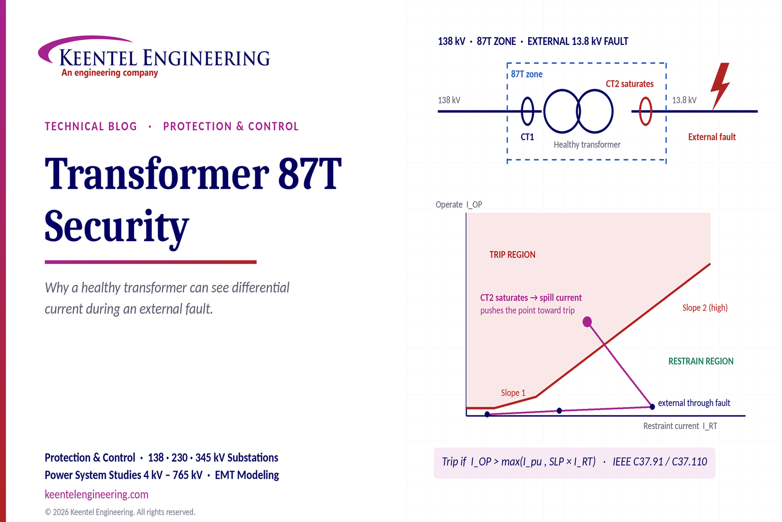
Learn why transformer differential relays detect current during external faults, how CT saturation causes spill current, and how secure 87T protection prevents trips.
By SANDIP R PATEL
•
October 10, 2026
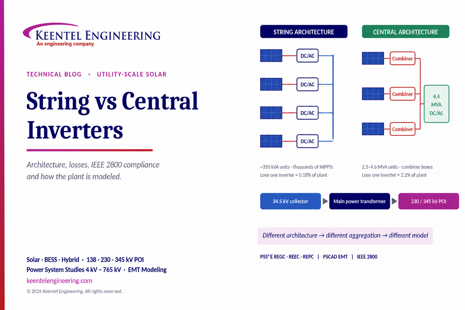
Compare string vs central inverters for utility-scale solar, including efficiency, maintenance, grid compliance, reactive power and interconnection studies.
By SANDIP R PATEL
•
October 9, 2026
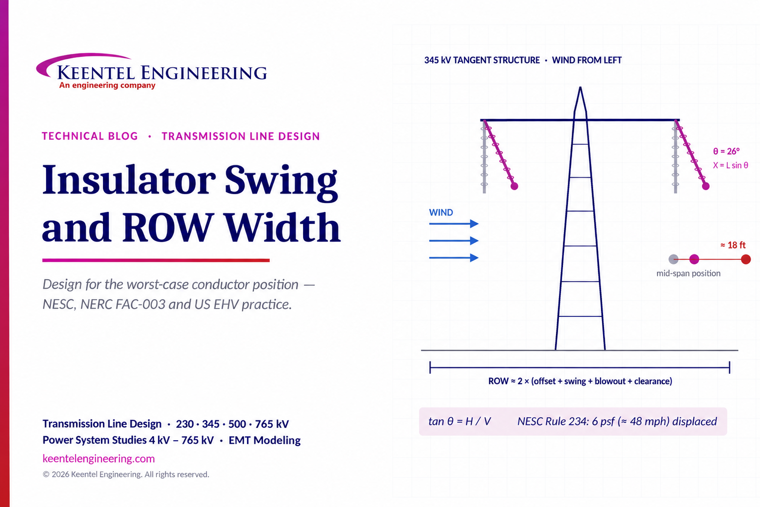
Learn how insulator swing angle and conductor blowout affect transmission line ROW width, with NESC clearances, NERC FAC-003 guidance, and a 345 kV example.
Copy

By SANDIP R PATEL
•
October 3, 2026
Engineering guide to PRC-028 disturbance recording, PRC-029 ride-through and PRC-030 event detection for inverter-based resources.

By SANDIP R PATEL
•
October 3, 2026
A practical guide to SSO classification, SSR, PEDI, Wind-SSCI, EMT analysis, mitigation and protection based on CIGRE TB 909.

By SANDIP R PATEL
•
October 3, 2026
Learn ERCOT generator testing for PFR, MOD-025 and MOD-026/027, including staged tests, capability verification, dynamic models and field testing.





