
A Coordinated Electric System Interconnection Review—the utility’s deep-dive on technical and cost impacts of your project.
Challenge: Frequent false tripping using conventional electromechanical relays
Solution: SEL-487E integration with multi-terminal differential protection and dynamic inrush restraint
Result: 90% reduction in false trips, saving over $250,000 in downtime
ERCOT enforces all of the above through simulation, which means your model is your compliance case. The bar is now high:
- Whole-facility scope. The model must represent everything the IT load, the UPS and power conversion, the cooling plant, the protection and control systems in formats compatible with ERCOT's study platforms (PSS/E, PSCAD, TSAT).
- Real control loops, not approximations. Generic textbook representations are unacceptable. The model must capture the actual inner control behavior of your power electronics.
- Hardware-validated converter models. For electronic loads, the PSCAD model must be benchmarked against actual hardware testing including voltage ride-through and subsynchronous response. A model assembled from standard PSCAD library blocks fails by definition, because a generic block has never been tested against your vendor's hardware. The good news: validation is a hardware-type test, so results for a given converter product are reusable across every facility that uses it.
- Format migration. Facilities that previously submitted the older composite load model (CMLD) format must transition to EPRI's PERC1 format.
- Three checkpoints. Models are reviewed before the stability study begins (no model, no study), before each quarterly stability assessment, and for electronic loads one final time before energization, when you must submit as-built models with a documented comparison against the previously studied data and a sworn attestation that the model matches actual field settings. ERCOT's review takes 10 business days, extendable by 20 put it on your critical path.
- A living obligation. Change your technology, controls, or relay settings in a way that affects ride-through including converting a crypto mining site to an AI data center — and you've triggered a new interconnection study, even if your megawatts don't change.
| Parameter | Detail |
|---|---|
| System | 230 kV / 138 kV transmission corridors, wind and wet-snow icing exposure |
| Data basis | 15 years of minute-resolution forced-outage records + regional weather observations |
| Core methods | Event grouping, MVA performance curves, time-to-95%-restore, area outage rate curves, fragility modeling, rerun-history benefits, exceedance and log-domain risk metrics |
| Headline result | ≈85% of maximum resilience benefit at 60% of original capital; worst-event restoration window cut from 11 days to 5 in rerun-history terms |
| Decision supported | Capital portfolio selection; resilience plan filing; post-investment verification framework |
| System / Topic | Governing Standard(s) | What It Controls |
|---|---|---|
| Overall plant electrical distribution | IEEE 141 (Red Book); IEEE 666 | Distribution architecture, voltage selection, design of generating station auxiliary service systems |
| Power system studies | IEEE 399 (Brown Book); IEEE 551 | Load flow, symmetrical/asymmetrical short circuit, motor starting methodologies down to the lowest LV panelboard |
| Protection & coordination | IEEE 242 (Buff Book); IEEE 3004.5; IEEE C37 series | Generator relaying (21, 59N, 87G), time-current coordination, selective clearing between LV and MV tiers |
| GSU / UAT / SST transformers | IEEE C57.12.00 and C57 family | Transformer ratings, impedance, testing, loading |
| HV switchyard breakers | IEEE C37.06 | AC high-voltage circuit breaker preferred ratings |
| MV switchgear (13.8 kV) | IEEE C37.20.2; IEEE C37.20.7 | Metal-clad construction, compartmentalization, vacuum breakers; arc-resistant design with plenum venting |
| MV cable | UL 1072; ICEA S-93-639 (NEMA WC 74) | Type MV-105 shielded cable, 133% insulation level for HRG systems |
| LV switchgear (480 V) | IEEE C37.13; UL 1558 | Metal-enclosed LV power circuit breaker switchgear to 635 V, draw-out ACBs with electronic trip units |
| Motor control centers | UL 845; NEMA ICS 18 | LV-MCC construction, MCCB/MCP protection for motors under ~200 HP |
| Motors | NEMA MG-1 | Motor performance, starting characteristics, service factors |
| DC & battery systems | IEEE 485; IEEE 946 | Lead-acid battery sizing (125/250 VDC), DC auxiliary system design |
| Grounding | IEEE 80; IEEE 142 (Green Book) | Ground grid step/touch potential limits; system grounding including high-resistance grounding |
| Lightning protection | IEEE 998 | Direct-stroke shielding of switchyard and outdoor generator structures |
| Arc flash & electrical safety | IEEE 1584; NFPA 70E | Incident energy calculation; worker safety boundaries and PPE |
| Fire protection | NFPA 850 | Fire protection and risk management for combustion turbine generating plants |
| Installation code | NEC (NFPA 70); NESC | Wiring methods inside the plant fence; overhead/outdoor clearances at the switchyard |
| Interconnection & compliance | FERC LGIP; NERC MOD-025/026/027, PRC-019/024/029, FAC-008 | Interconnection process, model validation, protection/ride-through coordination, facility ratings |
| IFC / Construction Deliverable | Purpose |
|---|---|
| Stamped IFC packages | Legal basis for construction; P.E. responsible charge |
| Final relay settings & TCCs | Protection as-installed matches the coordination study |
| Calculation archive | Owner records; NERC audit evidence trail |
| Commissioning procedures | Safe, sequenced energization; MOD field testing |
| Construction support | RFIs, field changes, FAT/SAT witness |
| As-builts & model handoff | Operating baseline; future study currency |
| Metric | Outcome |
|---|---|
| Defects found pre-occupancy | Three topology defects and one settings-mismatch family corrected before load migration; the shared-switchboard defect alone would have invalidated the concurrently-maintainable claim on day one |
| IST findings | Fourteen additional discrepancies surfaced under scenario testing (control logic, alarm mapping, one generator sequencing fault) — all closed before handover instead of during operations |
| Black-building test | Passed on second execution; the first attempt exposed the generator sequencing fault under true block load, exactly the failure the compressed plan would never have found |
| Handover quality | Operations team certified on the actual failure scenarios; corrected EOPs and settings documentation delivered as controlled documents |
| Business outcome | Occupancy proceeded three weeks behind the original date — against an independent estimate that the uncorrected sequencing fault carried a high probability of a full facility outage within the first year |
IEEE Standards and How Keentel Engineering Puts Them to Work
Jul 13, 2026 | Blog
Disclaimer
This document is published by Keentel Engineering for educational and informational purposes. Keentel Engineering is an independent consulting engineering firm and is not affiliated with, endorsed by, or sponsored by IEEE, the Bureau of Indian Standards (BIS), the International Electrotechnical Commission (IEC), NERC, FERC, or any equipment manufacturer or standards body referenced herein. All trademarks and standard designations are the property of their respective owners. Standards are revised periodically; readers should always verify the current edition and any amendments before applying requirements to a specific project. The case studies in this document are fully anonymized composites drawn from representative project experience; names, locations, ratings, and identifying details have been altered.
Introduction: Standards Are Design Inputs, Not Checkboxes
Every substation, solar plant, battery energy storage system (BESS), and industrial facility that Keentel Engineering touches is shaped by a common body of engineering law: the IEEE standards. These documents are not paperwork to be cited at the end of a project — they are first-order design inputs that determine conductor sizes, grounding grid geometry, relay settings, battery capacity, harmonic filters, and even the anchor bolts under a transformer. At Keentel Engineering, we treat grid interconnection and power system studies the same way: as engineering that must be done early, correctly, and to the letter of the governing standard.
This blog walks through eleven of the most consequential IEEE standards in power engineering — the same standards that appear on virtually every utility technical-requirements document and interconnection agreement — and explains, standard by standard, how Keentel Engineering's workflows, software toolchain, and deliverables align with each one.
Strip away the vendor language and every data center resolves into the same functional blocks. A secure envelope encloses one or more data halls of IT cabinets. Utility power enters through an intake substation, flows through medium- and low-voltage switchgear, is conditioned and bridged by uninterruptible power supply (UPS) systems, backed by standby generation, and delivered to racks through power distribution units (PDUs), busway, or rack power panels. Heat leaves through a cooling chain — room or row-level air handlers, chilled water or refrigerant loops, and external heat rejection — sized to remove essentially every watt the electrical system delivers. Around this core sit the support spaces: plant rooms, battery rooms, network intake rooms at diverse building entries, loading and build/test areas, a network operations center, and the security layers that control movement among them all.
Rack power density is the design variable that drives everything else. Legacy enterprise cabinets at 2–5 kW, virtualized and blade environments at 8–15 kW, dense compute at 20–40 kW, and current-generation AI training racks at 80–150 kW and climbing represent fundamentally different electrical distribution, cooling, and structural problems — not scaled versions of one problem. A hall designed for uniform 8 kW air-cooled racks cannot absorb a 120 kW liquid-cooled AI pod without touching the power chain, the cooling topology, the floor loading, and often the utility supply itself. Because IT refreshes every two to five years while the building and plant last decades, the highest-value design decision is the one that keeps density growth from becoming a rebuild: oversized risers and containment routes, plant rooms with expansion positions, electrical architectures that scale in modules, and a site with secured headroom at the point of interconnection.
| Standard | Title (Short) | Core Subject |
|---|---|---|
| IEEE 80 | Guide for Safety in AC Substation Grounding | Touch/step voltage limits, grid design, GPR |
| IEEE 81 | Measuring Earth Resistivity & Grounding Impedance | Soil resistivity testing, fall-of-potential, grid impedance |
| IEEE 142 (Green Book) | Grounding of Industrial & Commercial Power Systems | System/equipment grounding philosophy |
| IEEE 1584 | Guide for Arc-Flash Hazard Calculations | Incident energy, arc-flash boundaries, PPE categories |
| IEEE 485 | Sizing Lead-Acid Batteries for Stationary Applications | DC system and battery sizing for substations |
| IEEE 519 | Harmonic Control in Electric Power Systems | Voltage/current distortion limits at the PCC |
| IEEE 1547 | Interconnection of Distributed Energy Resources | DER interconnection, ride-through, power quality |
| IEEE 1159 | Monitoring Electric Power Quality | Sags, swells, transients, monitoring practice |
| IEEE 693 | Seismic Design of Substations | Equipment qualification for seismic performance |
| IEEE 1815 | DNP3 Communication Protocol | SCADA/RTU communications for power systems |
| IEEE C37 Series | Switchgear, Circuit Breakers & Protection | Breaker ratings, relays, protection standards |
Keentel Perspective
A standards-aligned design is cheaper than a standards-remediated one. Nearly every costly field change order we have reviewed as owner's engineer traces back to a standard that was applied late — a grounding grid sized before soil data existed, a battery sized without IEEE 485 duty cycles, or an arc-flash label printed from an outdated IEEE 1584 model.
IEEE 80 Safety in AC Substation Grounding
What the standard covers
IEEE 80 is the governing guide for the design of substation grounding systems. It defines the safety criteria — tolerable touch voltage, step voltage, and ground potential rise (GPR) — based on human body current limits, fault duration, and surface material, and it provides the methodology for sizing grounding conductors, arranging grid meshes and ground rods, and verifying that a fault on the system does not create lethal potentials for personnel or the public.
How Keentel Engineering aligns
- Every Keentel substation and collector-station grounding design begins with an IEEE 80 safety analysis performed in dedicated grounding software (WinIGS/CDEGS-class tools), modeling the actual grid geometry, soil model, and split-factor fault current rather than hand approximations.
- We size grid conductors and connections for the X/R-adjusted fault current and clearing time from the protection study — coordinating IEEE 80 with the C37-based relay settings so the assumed fault duration is the real one.
- Touch and step voltages are checked at fences, gates, equipment operating handles, and adjacent metallic structures, with crushed-rock surfacing derating applied per IEEE 80.
- Deliverables include a stamped grounding study report with GPR, tolerable-limit calculations, mesh/touch/step contour plots, and a construction-ready grounding plan.
IEEE 81 Earth Resistivity and Grounding Impedance Measurement
What the standard covers
IEEE 81 defines how to measure the things IEEE 80 needs as inputs: soil resistivity (Wenner four-point and Schlumberger arrays), grounding grid impedance (fall-of-potential method), and continuity of grounding connections. A grounding design is only as good as the soil model beneath it, and IEEE 81 is the standard that keeps that model honest.
How Keentel Engineering aligns
- Keentel specifies IEEE 81 Wenner-array soil resistivity testing at multiple traverses and probe spacings during the site-investigation phase — before 30% design — so the two-layer (or multilayer) soil model is a measured quantity, not an assumption.
- We develop test plans and review contractor field data for validity: probe spacing versus depth of interest, seasonal moisture effects, and interference from buried metallic objects.
- For energized or existing stations, we specify fall-of-potential grid impedance testing per IEEE 81 to validate as-built performance against the IEEE 80 design model.
- Measured data is reduced into layered soil models directly inside our grounding software, closing the loop between field measurement and design.
IEEE 142 (Green Book) Grounding of Industrial and Commercial Power Systems
What the standard covers
The IEEE Green Book addresses grounding philosophy inside the fence and inside the plant: whether a system should be solidly grounded, low- or high-resistance grounded, or ungrounded; how equipment grounding and bonding should be executed; and how static, lightning, and electronic-equipment grounding interact with the power system.
How Keentel Engineering aligns
- Keentel applies IEEE 142 when selecting the grounding method for collector systems, auxiliary power systems, and industrial facilities — for example, low-resistance grounding of a 34.5 kV collector neutral to limit ground-fault damage while keeping faults detectable.
- Our medium-voltage design packages document the grounding decision explicitly, with fault-current, protection-sensitivity, and transient-overvoltage justifications drawn from the Green Book.
- We coordinate IEEE 142 equipment grounding and bonding details with the IEEE 80 grid design so the below-grade and above-grade systems behave as one network.
IEEE 1584 Arc-Flash Hazard Calculations
What the standard covers
IEEE 1584 provides the empirically derived model for calculating arc-flash incident energy and arc-flash boundary distances in low- and medium-voltage equipment. The 2018 edition substantially revised the model — introducing electrode configuration factors and enclosure-size corrections — and remains the basis for the labels, PPE selection, and safe work boundaries required by workplace electrical safety programs.
How Keentel Engineering aligns
- Keentel performs arc-flash studies using the current IEEE 1584 model in ETAP/SKM-class software, built on a verified short-circuit model and the actual protective device settings from our coordination study — never on assumed clearing times.
- We evaluate incident-energy reduction options as part of the study: maintenance-mode switches, zone-selective interlocking, differential zones, and faster settings validated against selectivity requirements.
- Deliverables include equipment labels, an incident-energy table, and an engineering report identifying every bus above target energy thresholds with concrete mitigation recommendations.
- Legacy studies performed under the 2002 model are flagged for re-study — the 2018 equations can move results materially in either direction.
IEEE 485 Battery Sizing for Stationary Applications
What the standard covers
IEEE 485 defines the method for sizing vented and valve-regulated lead-acid batteries for stationary duty — the DC systems that trip breakers, run protection relays, and keep SCADA alive when the station itself is dead. It formalizes the duty cycle, the section-by-section sizing calculation, and the aging, temperature, and design margins that must be applied.
How Keentel Engineering aligns
- Keentel builds a complete IEEE 485 duty cycle for every substation DC system we design: continuous relay and RTU load, momentary breaker-trip inrush, and the emergency-lighting or communications tail load over the specified backup period.
- We apply the standard's aging (typically 125%), temperature, and design-margin factors and document them transparently so the owner can see exactly why the battery is the size it is.
- Battery sizing is coordinated with charger sizing, DC voltage-window checks at the relay terminals (including end-of-discharge voltage drop), and the C37-driven trip duty of the actual breaker population.
- For non-lead-acid chemistries we apply the companion IEEE practices and manufacturer data while preserving the IEEE 485 duty-cycle discipline.
IEEE 519 Harmonic Control in Electric Power Systems
What the standard covers
IEEE 519 establishes the recommended limits for harmonic voltage distortion supplied by the utility and harmonic current distortion injected by users, measured at the point of common coupling (PCC). With inverter-based resources, VFD-heavy industrial loads, and data centers proliferating, IEEE 519 compliance has become a routine interconnection requirement.
How Keentel Engineering aligns
- Keentel performs harmonic studies for solar, BESS, and large-load interconnections, modeling inverter harmonic spectra against the frequency-dependent network impedance — including resonance introduced by collector cable capacitance and harmonic filters.
- We evaluate compliance at the correct PCC with the correct short-circuit-ratio-based current limits from the standard's tables, not generic thresholds.
- Where limits are exceeded, we design mitigation — tuned filters, C-type filters, or control-side solutions — and verify performance across contingency network conditions.
- Harmonic study results feed directly into our power quality monitoring recommendations under IEEE 1159, so compliance can be demonstrated after energization, not just predicted before it.
IEEE 1547 Interconnection of Distributed Energy Resources
What the standard covers
IEEE 1547 (with its 2018 revision and the 1547.1 test standard) is the national framework for interconnecting distributed energy resources — solar PV, BESS, and other inverter-based resources — with distribution and area electric power systems. It defines voltage and frequency ride-through, voltage regulation functions (volt-var, volt-watt), power quality requirements, and interoperability.
How Keentel Engineering aligns
- Keentel prepares IEEE 1547-conformant interconnection packages for distribution-connected solar and storage, including our community-solar and sub-5 MW project work, mapping each utility's technical requirements to the standard's performance categories (Category A/B and I/II/III).
- We specify and verify smart-inverter function settings — ride-through curves, volt-var and frequency-watt parameters — against both IEEE 1547-2018 and the interconnecting utility's adopted profile.
- Our power system studies (load flow, short circuit, protection impact) quantify the effects the standard is designed to manage: voltage regulation interaction, unintentional islanding risk, and protection desensitization.
- For transmission-connected IBRs we carry the same discipline into the NERC world — ride-through and disturbance-monitoring requirements such as PRC-029 and PRC-028 — so distribution and bulk-system compliance are handled as one continuum.
IEEE 1159 Monitoring Electric Power Quality
What the standard covers
IEEE 1159 is the recommended practice for monitoring and classifying power quality phenomena — sags, swells, interruptions, transients, harmonics, flicker, and unbalance — with consistent definitions, magnitude/duration categories, and monitoring methodology.
How Keentel Engineering aligns
- Keentel uses IEEE 1159 categories as the common language in every power quality investigation, so an event described in our reports means the same thing to the utility, the owner, and the equipment vendor.
- We develop monitoring plans — instrument placement, trigger thresholds, and recording durations — for commissioning of IBR plants and for diagnosing malfunction complaints at industrial facilities and data centers.
- Disturbance records from relays and dedicated PQ meters are analyzed against IEEE 1159 classifications and cross-referenced with our EMT and dynamic models to identify root cause rather than just symptoms.
IEEE 693 Seismic Design of Substations
What the standard covers
IEEE 693 provides the recommended practice for the seismic qualification of substation equipment — bushings, transformers, disconnect switches, instrument transformers, and their support structures — defining qualification levels (low, moderate, high) and the analysis or shake-table testing required to demonstrate performance.
How Keentel Engineering aligns
- For projects in seismically active regions — including our West Coast work — Keentel specifies the appropriate IEEE 693 qualification level in equipment procurement specifications and reviews vendor qualification reports for conformance.
- We coordinate equipment anchorage, foundation design inputs, and flexible-bus/conductor slack requirements with the structural engineer so seismic qualification is preserved by the installation, not defeated by it.
- As owner's engineer we verify that seismic documentation is complete at factory-acceptance and delivery — a detail that is inexpensive to check early and extremely expensive to discover missing later.
IEEE 1815 DNP3 Communication Protocol
What the standard covers
IEEE 1815 standardizes DNP3, the dominant SCADA communications protocol in North American utility systems. It defines the data models, event reporting, time synchronization, and — critically — Secure Authentication for communications between master stations, RTUs, and IEDs.
How Keentel Engineering aligns
- Keentel designs substation automation architectures — including SEL RTAC- and Axion-based systems — with IEEE 1815/DNP3 point maps engineered deliberately: class assignments, deadbands, event buffering, and time-sync strategy documented for the operating utility.
- We build integration test plans that exercise the DNP3 profile point-by-point during factory and site acceptance testing, so SCADA cutover is a verification exercise rather than a discovery exercise.
- Where projects mix IEC 61850 GOOSE/MMS inside the fence with DNP3 to the control center, we engineer the gateway mapping so no protection-critical or compliance-critical point is lost in translation.
- Secure Authentication and network segmentation recommendations are aligned with the owner's NERC CIP posture.
IEEE C37 Series Switchgear, Circuit Breakers, and Protection
What the standard covers
The C37 family is the backbone of protection and switchgear engineering: C37.04/.06/.09 for circuit breaker ratings and testing, C37.010 for application, C37.2 for device function numbers, C37.90 series for relay standards, C37.91–.119 protection guides for transformers, lines, buses, and generators, C37.20 series for switchgear assemblies, and C37.111 (COMTRADE) for disturbance records, among many others.
How Keentel Engineering aligns
- Keentel's short-circuit studies apply C37.010/C37.5 methodology so breaker interrupting duties are compared against nameplate ratings on the correct symmetrical/asymmetrical basis, including X/R correction.
- Our protection and coordination designs follow the applicable C37 protection guides — transformer differential and overcurrent per C37.91, line protection per C37.113, bus protection per C37.234 — and every one-line and schematic uses C37.2 device numbering.
- Relay settings files, coordination curves, and setting-basis documents are delivered as an auditable package that supports NERC PRC compliance obligations.
- Disturbance monitoring deliverables (DFR/relay event records) are specified in COMTRADE format per C37.111, which also underpins PRC-028 disturbance-monitoring compliance for inverter-based resources.
Pulling It Together: One Model, Many Standards
The most important thing about these eleven standards is that they are
coupled. The IEEE 80 grounding design depends on the C37-based clearing time. The IEEE 1584 arc-flash result depends on the same relay settings. The IEEE 485 battery must trip the C37-rated breakers. The IEEE 519 harmonic study and the IEEE 1547 interconnection functions interact through the same inverter controls. Keentel Engineering's practice is built around this coupling: one verified system model, one protection philosophy, and one set of studies that feed each other — delivered by licensed engineers who work with these standards every day across
grid interconnection substation design,
power system studies
NERC compliance, and owner's engineer engagements.
Key takeaway
Most 'full' legacy facilities are full on paper and stranded in practice. Measured capacity accounting, disciplined air management, and a block-architected power and liquid design turned a decade-old 6 kW hall into a home for 90 kW AI racks — live, without a new building, and with the whole facility running more efficiently than before the project started.
Anonymized Case Studies
The following case studies are fully anonymized composites representative of Keentel Engineering's project experience. Client names, locations, voltages, and ratings have been altered to protect confidentiality; the engineering issues and outcomes are authentic.
Case Study 1: IEEE 80/81 Grounding Redesign for a Utility-Scale Solar Collector Substation
| Parameter | Detail |
|---|---|
| Facility | ~150 MWac utility-scale solar plant with 34.5 kV/138 kV collector substation |
| Region | Southeastern U.S., high-resistivity layered soil |
| Standards Applied | IEEE 80, IEEE 81, IEEE 142, IEEE C37 (clearing times) |
| Keentel Role | Grounding study engineer of record |
| Tools | WinIGS-class grounding analysis, layered soil modeling |
The Challenge
The EPC's preliminary grounding design had been sized using an assumed uniform 100 Ω·m soil model carried over from a different site. Late-stage IEEE 81 Wenner testing revealed a high-resistivity upper layer over a conductive lower layer — a profile that dramatically changes current distribution in the grid and pushes touch voltages up at the grid perimeter. The utility's interconnection reviewer rejected the submitted study, putting the energization date at risk.
The Approach
Keentel re-reduced the raw IEEE 81 field data into a validated two-layer soil model, rebuilt the grid in full-geometry grounding software, and imported the actual single-line-to-ground fault current and split factor from the short-circuit study — with clearing time taken from the real C37-coordinated relay settings rather than a conservative placeholder. The analysis showed perimeter mesh voltages exceeding IEEE 80 tolerable touch limits at the fence and at two equipment operating positions.
The Solution
Rather than a costly wholesale re-trench, Keentel designed targeted reinforcement: perimeter conductor densification, deep-driven rods reaching the conductive lower layer, gradient-control loops at the fence and gates, and a verified crushed-rock surfacing specification with documented derating per IEEE 80. The revised design was validated in the model and packaged with GPR, tolerable-limit, and contour-plot documentation.
Results
- Touch and step voltages brought within IEEE 80 tolerable limits at all locations, with documented margin.
- Utility review passed on first resubmittal; energization date preserved.
- Reinforcement cost was a small fraction of the EPC's initially feared full-grid redesign.
- Post-construction IEEE 81 fall-of-potential testing confirmed grid impedance within 10% of the model prediction.
Lesson Learned
Soil resistivity data is the foundation of every grounding design. Measured IEEE 81 data must precede — not follow — IEEE 80 design. Copying a soil model between sites is one of the most expensive shortcuts in substation engineering.
Case Study 2: IEEE 1584 Arc-Flash and C37 Protection Modernization for an Industrial Facility
| Parameter | Detail |
|---|---|
| Facility | Anne |
| Region | Gulf Coast U.S. |
| Standards Applied | IEEE 1584-2018, IEEE C37 series, IEEE 242/3004-series coordination practice, IEEE 485 |
| Keentel Role | Power system study consultant |
| Tools | ETAP-class short-circuit, coordination, and arc-flash modeling |
The Challenge
The plant's arc-flash labels dated to a 2012 study performed under the IEEE 1584-2002 model, and the utility had since increased available fault current at the service entrance. Several main-tie-main lineups carried dangerously optimistic labels, and maintenance work practices were built around them. The owner also suspected miscoordination after a feeder fault had tripped a main breaker and dropped half the plant.
The Approach
Keentel rebuilt the system model from verified field data — nameplates, cable schedules, current relay settings files — and re-ran short-circuit duties per C37.010 methodology against breaker ratings. The coordination study was redone across all voltage levels, and arc flash was recalculated under IEEE 1584-2018 with correct electrode configurations and enclosure dimensions. The station battery supporting the 69 kV breakers was checked against an IEEE 485 duty cycle as part of the same engagement.
The Solution
The study identified two breakers with interrupting duties above nameplate at the new utility fault level, the miscoordinated feeder/main pair responsible for the plant-wide trip, and eleven buses where 2018-model incident energies exceeded the old labels — three of them severely. Keentel delivered revised C37-coordinated settings, maintenance-mode (arc-energy-reduction) switching on the worst lineups, replacement recommendations for the over-dutied breakers, updated labels for every bus, and a resized station battery calculation.
Results
- Full selectivity restored — subsequent feeder faults cleared at the feeder level with no plant-wide interruptions reported.
- Worst-case incident energy on the main lineups reduced by more than 60% in maintenance mode.
- Over-dutied breakers identified and replaced before failure rather than after.
- A current, defensible IEEE 1584-2018 label set supporting the owner's electrical safety program.
Lesson Learned
Arc-flash, short-circuit, coordination, and DC-system studies are one coupled problem. Updating labels without re-verifying breaker duties and coordination — or vice versa — leaves the most dangerous gaps untouched.
Case Study 3: IEEE 1547/519 Interconnection and Power Quality Engineering for a Distribution-Connected Solar-Plus-Storage Portfolio
| Parameter | Detail |
|---|---|
| Facility | Portfolio of community-scale solar and solar-plus-BESS sites, each under 5 MW, distribution-connected |
| Region | Northeastern and Midwestern U.S., multiple utilities |
| Standards Applied | IEEE 1547-2018, IEEE 1547.1, IEEE 519, IEEE 1159, IEEE 1815 (SCADA) |
| Keentel Role | interconnection |
| Tools | Load flow/short-circuit modeling, harmonic scan analysis, inverter settings verification |
The Challenge
A distributed-generation developer faced three different utilities with three different IEEE 1547-2018 adoption profiles — different ride-through categories, different volt-var default curves, and different study requirements. One flagship site also sat at the end of a long rural feeder with a weak short-circuit ratio, raising utility concerns about voltage regulation interaction and harmonic distortion at the PCC.
The Approach
Keentel built a standard interconnection engineering package that mapped each utility's technical requirements to the IEEE 1547-2018 performance categories, then tailored inverter certification documentation, settings tables, and study scopes per jurisdiction. For the weak-feeder site, a harmonic scan of the feeder impedance versus the certified inverter spectra was run across grid contingency conditions, and IEEE 519 current-distortion limits were evaluated at the utility-confirmed PCC using the actual short-circuit ratio.
The Solution
The studies demonstrated IEEE 519 compliance without external filters once inverter quantity-versus-loading behavior at low output was accounted for, and identified a volt-var curve adjustment that resolved the utility's regulation-interaction concern in simulation. Keentel documented IEEE 1547 Category settings site-by-site, specified DNP3 (IEEE 1815) point maps for the utilities requiring direct transfer-trip and curtailment interfaces, and defined an IEEE 1159-based post-energization monitoring plan to verify predicted performance.
Results
- All portfolio sites received interconnection approval without redesign; the weak-feeder flagship site avoided a six-figure harmonic filter through study-demonstrated compliance.
- A reusable, jurisdiction-mapped IEEE 1547 settings and documentation framework cut engineering cycle time on subsequent sites materially.
- Post-energization IEEE 1159 monitoring confirmed voltage regulation and distortion performance within study predictions, closing out utility conditions.
Lesson Learned
IEEE 1547-2018 is a framework, not a single rulebook — every utility adopts it differently. Portfolio developers save the most money when interconnection engineering is standardized around the framework and localized per utility, instead of reinvented site by site.
Frequently Asked Questions
Q1. What is the difference between IEEE 80 and IEEE 81?
IEEE 80 is the design guide — it tells you how to design a substation grounding system and what touch, step, and GPR limits it must meet. IEEE 81 is the measurement guide — it tells you how to measure soil resistivity and grounding impedance in the field. IEEE 81 produces the inputs; IEEE 80 consumes them. A grounding study that skips proper IEEE 81 soil testing is built on guesswork.
Q2. Why does my utility require an IEEE 80 grounding study for my solar or BESS project?
Because your collector substation introduces new ground-fault current sources and new GPR at the site. Utilities require a demonstrated-safe grounding design before energization, and most interconnection agreements explicitly reference IEEE 80. The study also protects your own O&M personnel, fences, and neighboring infrastructure.
Q3. Our arc-flash study was done in 2015. Is it still valid?
Probably not. IEEE 1584-2018 replaced the 2002 calculation model with new equations, electrode configurations, and enclosure corrections that can change incident energy significantly. Separately, studies should be reviewed whenever the system changes (new sources, changed settings, utility fault-current updates) and periodically as a matter of electrical safety program hygiene. Keentel recommends re-study under the 2018 model.
Q4. Does IEEE 1584 tell me what PPE to wear?
Not directly. IEEE 1584 calculates incident energy and arc-flash boundary. PPE selection based on those results is governed by workplace electrical safety practice (e.g., NFPA 70E in the U.S.). Keentel's arc-flash deliverables provide the calculated energies and labels that your safety program consumes.
Q5. What does IEEE 485 actually add over just picking a big battery?
Discipline and defensibility. IEEE 485 forces you to build the real duty cycle — every trip, every continuous load, every emergency-period load — and then apply documented aging, temperature, and design margins. The result is a battery that is provably adequate at end of life on the coldest credible day, and a calculation a utility or auditor can review.
Q6. Where is the point of common coupling (PCC) for IEEE 519 compliance?
The PCC is the point where the utility serves you and could serve other customers — commonly the primary side of your interconnection or service transformer. Its location matters enormously, because IEEE 519 current-distortion limits scale with the short-circuit ratio at that point. Keentel confirms the PCC with the interconnecting utility before running any harmonic study.
Q7. Does IEEE 519 apply to inverter-based solar and BESS plants?
Yes — utilities routinely apply IEEE 519 limits at the POI/PCC for IBR interconnections, and the harmonic behavior of hundreds of inverters interacting with collector-cable capacitance can create resonances that surprise developers. A pre-energization harmonic study is far cheaper than a post-energization filter retrofit.
Q8. What changed in IEEE 1547-2018 versus the original standard?
The 2018 revision transformed DERs from passive devices that tripped offline during disturbances into grid-supportive resources: mandatory voltage and frequency ride-through categories, voltage-regulation functions such as volt-var and volt-watt, frequency-watt response, interoperability requirements, and defined performance categories. Most utilities have now adopted 1547-2018-based technical requirements.
Q9. My project is transmission-connected. Does IEEE 1547 still apply?
IEEE 1547 formally covers DERs at distribution-level interconnections. Transmission-connected IBRs are governed by NERC reliability standards (e.g., ride-through and disturbance monitoring requirements) and regional/utility requirements — but the engineering concepts are continuous, and many utilities borrow 1547 concepts. Keentel works across both regimes daily.
Q10. What is IEEE 1159 used for in practice?
It provides the standard vocabulary and categories for power quality events — what counts as a sag versus an interruption, momentary versus temporary, and so on — plus monitoring methodology. When Keentel investigates equipment trips or nuisance events, IEEE 1159 classification is what turns a pile of waveform records into an actionable diagnosis.
Q11. Do I need IEEE 693 seismic qualification outside California?
IEEE 693 applies wherever seismic hazard justifies it — the qualification level (low/moderate/high) is selected from the site's seismic criteria. Many owners and utilities in moderate-hazard regions still specify IEEE 693 for critical equipment because a failed bushing or transformer after an earthquake is a months-long outage.
Q12. Is DNP3 (IEEE 1815) being replaced by IEC 61850?
Inside the substation, IEC 61850 GOOSE and MMS are increasingly dominant. But DNP3 remains the workhorse protocol from substation to control center across North America, and IEEE 1815 Secure Authentication continues to evolve. Most real projects — including Keentel's RTAC/Axion automation designs — are hybrid: 61850 inside the fence, DNP3 to SCADA.
Q13. What is the IEEE C37 series and why does it appear on every drawing?
C37 is the family of standards covering switchgear, circuit breakers, relays, and protection practice. The device numbers on every one-line (50, 51, 87, 21, etc.) come from C37.2; breaker ratings are per C37.04/.06; protection philosophies for transformers, lines, and buses come from the C37.9x/.1xx guides; and disturbance records use C37.111 COMTRADE. It is the shared grammar of protection engineering.
Q14. How do these IEEE standards relate to NERC compliance?
NERC standards define what the bulk power system must achieve; IEEE standards largely define how competent engineering achieves it. For example, PRC protection standards are executed through C37-based relay engineering, and disturbance-monitoring requirements such as PRC-028 rely on COMTRADE-format records per C37.111. Keentel delivers engineering that satisfies both layers simultaneously.
Q15. Can Keentel perform these studies with stamped deliverables?
Yes. Keentel Engineering (FL Engineering Firm Registry No. 36853) provides licensed professional engineering across grounding (IEEE 80/81), arc flash (IEEE 1584), DC systems (IEEE 485), harmonics and power quality (IEEE 519/1159), DER interconnection (IEEE 1547), protection and switchgear application (C37 series), substation automation (IEEE 1815/DNP3, IEC 61850), and seismic specification review (IEEE 693), with PE-stamped reports where required.
Q16. What information do you need from us to start?
Typically: a single-line diagram, utility fault-current and interconnection data, equipment nameplates or datasheets, relay setting files if they exist, site geotechnical/soil data for grounding work, and the governing utility technical requirements. Keentel provides a tailored data-request checklist at kickoff so nothing stalls mid-study.
Work With Keentel Engineering
Whether you need an IEEE 80/81 grounding study, an IEEE 1584 arc-flash refresh, IEEE 519/1547 interconnection studies for a solar or BESS project, or a full standards-aligned
substation design Keentel Engineering delivers stamped, utility-ready engineering. Call 813-389-7871 or email contact@keentelengineering.com.
About Keentel Engineering
Keentel Engineering is a power systems and grid interconnection consulting firm headquartered in Tampa, Florida, with offices in Austin, Sacramento, and Baltimore (FL Engineering Firm Registry No. 36853). Our services span
grid interconnection and POI engineering, power system studies, substation and transmission design, EMT modeling, renewables and BESS engineering, NERC compliance, and owner's engineer services — all delivered by licensed engineers who treat interconnection and standards compliance as first-order design inputs, not late-stage administrative steps.
| Contact | Detail |
|---|---|
| Phone | 813-389-7871 |
| contact@keentelengineering.com | |
| Web | www.keentelengineering.com |
| Headquarters | 400 N Ashley Dr, STE #2600, Tampa, FL 33602 |
| Offices | Tampa • Austin • Sacramento • Baltimore |

About the Author:
Sandip "Sonny" R. Patel, P.E.
IEEE Senior Member · Founder & CEO, Keentel Engineering
In 1995, Sonny Patel earned his Electrical Engineering degree from the University of Illinois. But degrees don't build legacies — action does.
For three decades, he has worked the power industry from every side of the table: 16 years as a utility engineer at Exelon/Commonwealth Edison; generation leadership across hydroelectric, industrial steam turbine, and a 9 GW renewable fleet; NERC Regional Entity Senior Compliance Engineer and Audit Team Lead, auditing some of the nation's largest utilities; and testing and commissioning lead on equipment up to 765 kV — the very top of the North American grid.Utility. Generator. Regulator. Consultant. Few engineers have seen all four seats. Fewer still have sat in them.
His experience spans nuclear, hydro, conventional generation, renewables, oil and gas, mining — and today's data centers, where he is authoring a three-book series on data center design. He is a Licensed Professional Engineer in six states and a Licensed Electrical Contractor in Florida (Unlimited EC) — he doesn't just design the work; he's qualified to stand behind its execution.Today, as Founder and CEO of Keentel Engineering, Sonny leads a nationwide team of engineers delivering substation design, power system studies, NERC compliance, and commissioning — done right, coast to coast.Three decades. Every side of the table. One standard: accountable engineering.
Services

Let's Discuss Your Project
Let's book a call to discuss your electrical engineering project that we can help you with.
About the Author:
Sandip "Sonny" R. Patel, P.E.
IEEE Senior Member · Founder & CEO, Keentel Engineering
In 1995, Sonny Patel earned his Electrical Engineering degree from the University of Illinois. But degrees don't build legacies — action does.
For three decades, he has worked the power industry from every side of the table: 16 years as a utility engineer at Exelon/Commonwealth Edison; generation leadership across hydroelectric, industrial steam turbine, and a 9 GW renewable fleet; NERC Regional Entity Senior Compliance Engineer and Audit Team Lead, auditing some of the nation's largest utilities; and testing and commissioning lead on equipment up to 765 kV — the very top of the North American grid.
Utility. Generator. Regulator. Consultant. Few engineers have seen all four seats. Fewer still have sat in them.
His experience spans nuclear, hydro, conventional generation, renewables, oil and gas, mining — and today's data centers, where he is authoring a three-book series on data center design. He is a Licensed Professional Engineer in six states and a Licensed Electrical Contractor in Florida (Unlimited EC) — he doesn't just design the work; he's qualified to stand behind its execution.
Today, as Founder and CEO of Keentel Engineering, Sonny leads a nationwide team of engineers delivering substation design, power system studies, NERC compliance, and commissioning — done right, coast to coast.Three decades. Every side of the table. One standard: accountable engineering.
Leave a Comment
Thank you for contacting us.
We will get back to you as soon as possible.
We will get back to you as soon as possible.
Oops, there was an error sending your message.
Please try again later.
Please try again later.
Related Posts

By SANDIP R PATEL
•
October 11, 2026
Explore grid inertia, RoCoF and frequency response, with swing equation calculations, frequency nadir analysis and US power system simulation examples.

By SANDIP R PATEL
•
October 10, 2026
Learn BESS DC sizing with power, energy, current and C-rate calculations, battery losses, degradation and a 100 MW/400 MWh utility-scale example.

By SANDIP R PATEL
•
October 10, 2026
Learn how BESS ROI is calculated using peak shaving, energy arbitrage, power quality and battery storage economics, with a practical 5 MW/10 MWh example.
By SANDIP R PATEL
•
October 10, 2026
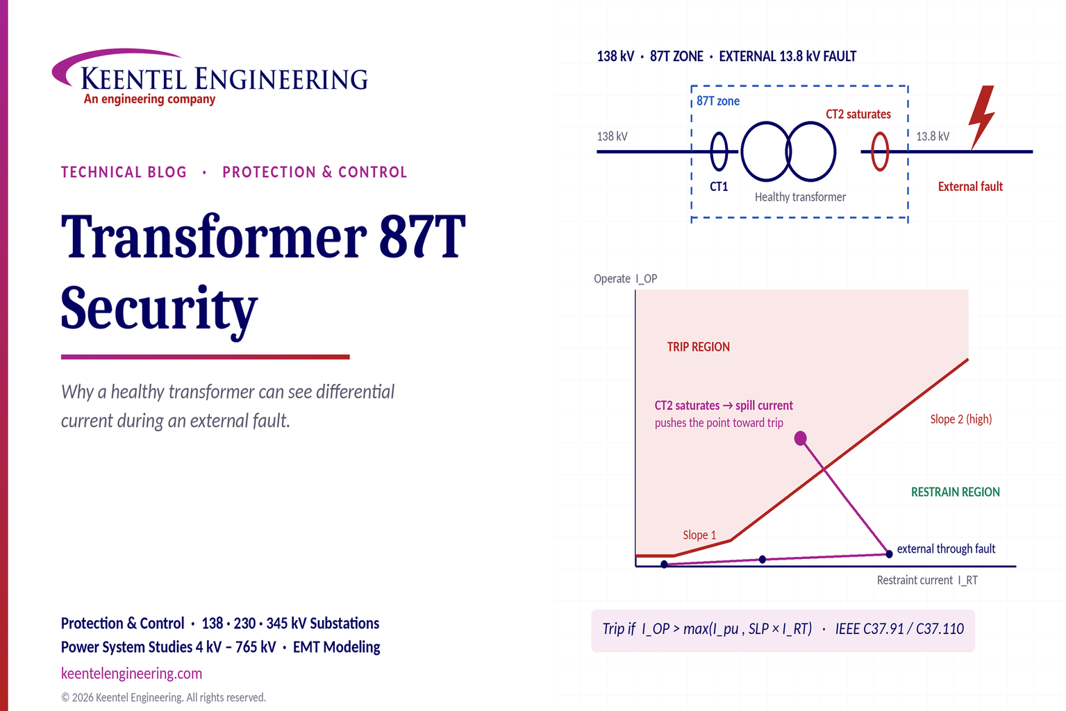
Learn why transformer differential relays detect current during external faults, how CT saturation causes spill current, and how secure 87T protection prevents trips.
By SANDIP R PATEL
•
October 10, 2026
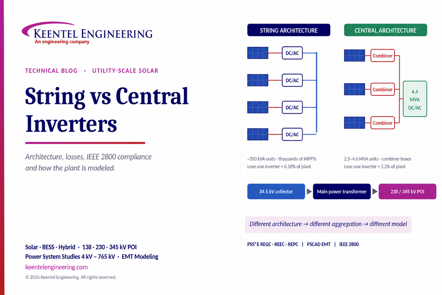
Compare string vs central inverters for utility-scale solar, including efficiency, maintenance, grid compliance, reactive power and interconnection studies.

By SANDIP R PATEL
•
October 3, 2026
Engineering guide to PRC-028 disturbance recording, PRC-029 ride-through and PRC-030 event detection for inverter-based resources.

By SANDIP R PATEL
•
October 3, 2026
A practical guide to SSO classification, SSR, PEDI, Wind-SSCI, EMT analysis, mitigation and protection based on CIGRE TB 909.

By SANDIP R PATEL
•
October 3, 2026
Learn ERCOT generator testing for PFR, MOD-025 and MOD-026/027, including staged tests, capability verification, dynamic models and field testing.

By SANDIP R PATEL
•
October 3, 2026
Learn how PV string I-V curve testing identifies hidden solar performance losses, including soiling, shading, mismatch, degradation, and wiring faults.





