


Learn how data centers work, from electrical systems and cooling infrastructure to redundancy, uptime, and grid interconnection planning.
Learn how data center electrical design, UPS systems, redundancy architecture, and interconnection planning ensure reliable power delivery.
Learn how data center cooling design, hot aisle containment, and chilled water systems improve efficiency, reliability, and power planning. Discover more.
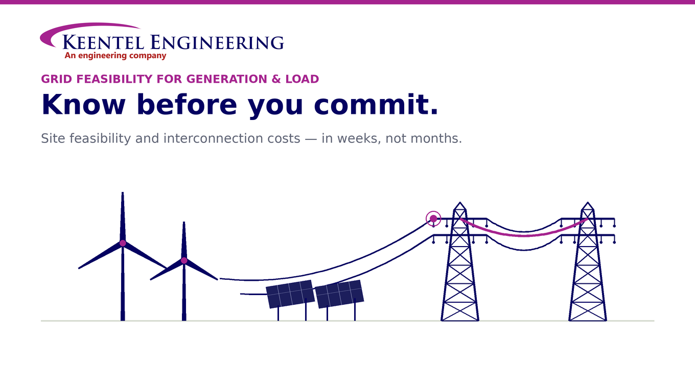
Power siting feasibility study, interconnection cost analysis, and grid capacity assessment. Discover site viability before investing. Learn more.
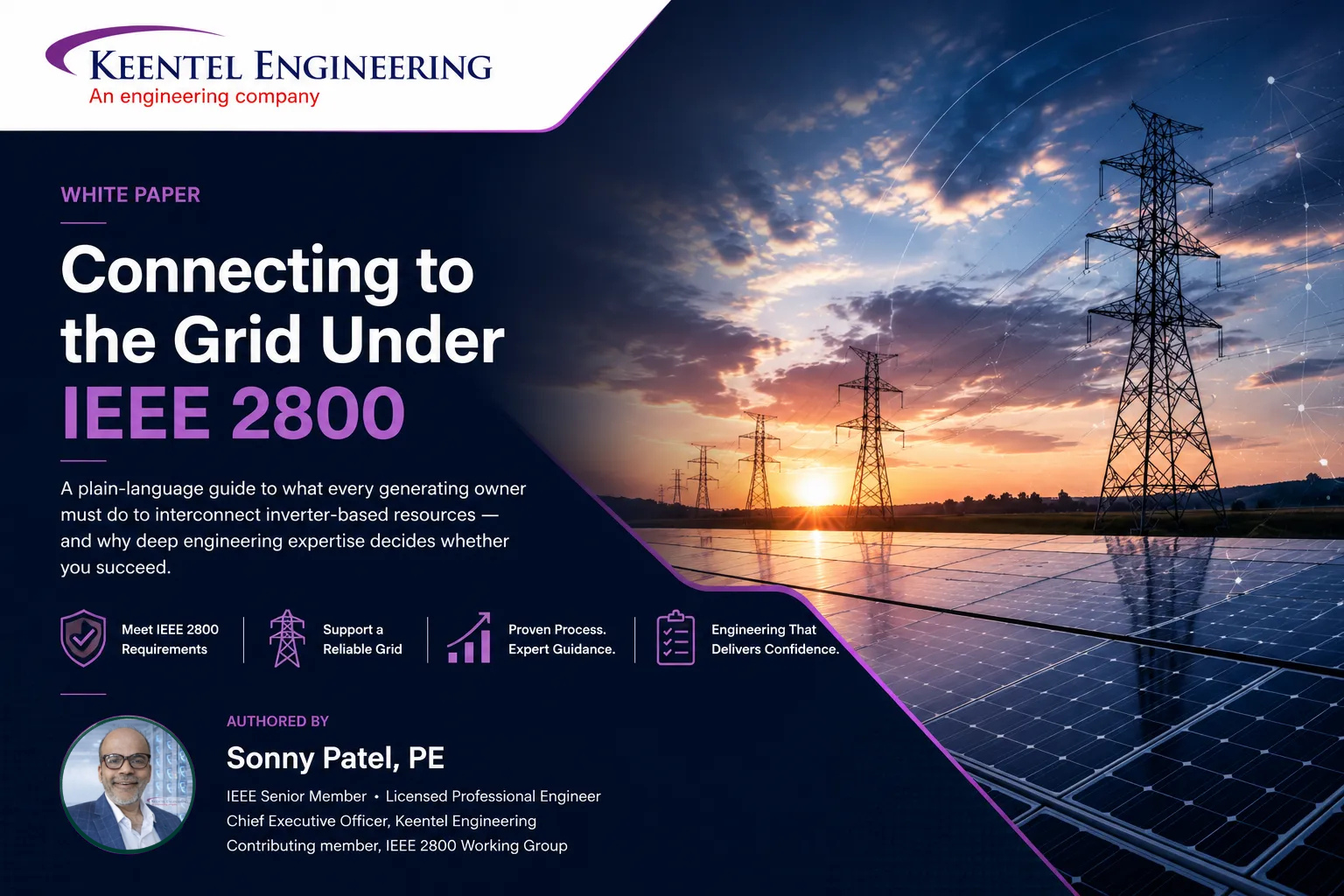
A practical engineering guide to IEEE 2800 compliance for inverter-based resources, including ride-through, EMT modeling, reactive power, protection coordination, and utility-scale interconnection requirements.
Explore data center site viability, grid interconnection risks, and power-water constraints. Learn engineering factors before site commitment.
Learn how generation injection, large load interconnection studies, and transmission interconnection services help secure the best POI and streamline approvals.
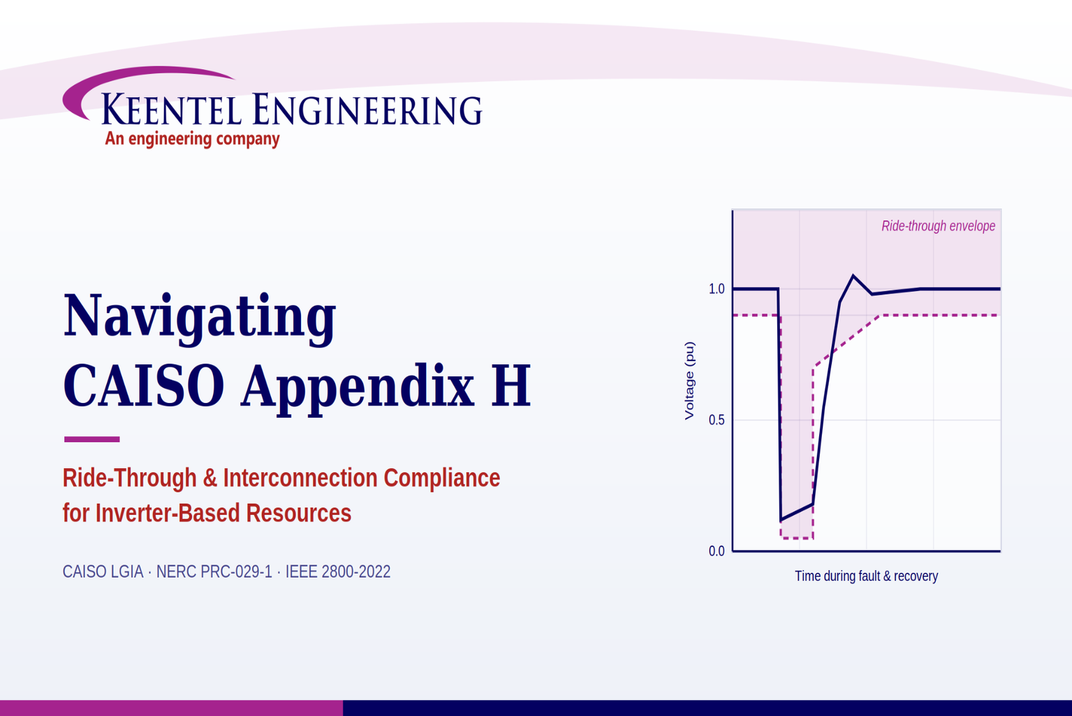
Learn CAISO Appendix H compliance, ride-through rules, and PRC-029-1 alignment for IBR projects. Discover expert engineering support.
Owner’s Engineer services for BESS and HV substations. Reduce project risk with design review, commissioning support, and bankability insight. Learn more.


