
A Coordinated Electric System Interconnection Review—the utility’s deep-dive on technical and cost impacts of your project.
Challenge: Frequent false tripping using conventional electromechanical relays
Solution: SEL-487E integration with multi-terminal differential protection and dynamic inrush restraint
Result: 90% reduction in false trips, saving over $250,000 in downtime
The three operating regions you have to design to
| Device | Output vs voltage | Response | Best suited to | Main limitations |
|---|---|---|---|---|
| Mechanically switched capacitor or reactor | Proportional to voltage squared | Seconds; discrete steps; limited switching operations per day | Steady-state reactive supply, voltage profile, loss reduction | No dynamic capability; step voltage change on switching; capability collapses when most needed |
| Static var compensator | Capacitive branches proportional to voltage squared | A few cycles; continuously controllable | Continuous control where cost matters and deep voltage support is not the driver | Square-law capability loss; harmonic filters are part of the plant and interact with the network |
| STATCOM | Approximately proportional to voltage — constant current capability | One to two cycles closed loop; converter response faster still | Voltage stability margin, weak interconnections, fast disturbance recovery, flicker and unbalance compensation | Higher capital cost; converter losses; adds a converter and its control dynamics to the network |
| Synchronous condenser | Governed by machine capability and excitation | Excitation response in the hundreds of milliseconds; inherent inertial response instantaneous | System strength and inertia, short-circuit contribution, black start support | Rotating plant with maintenance and losses; slower controlled response than a converter |
| STATCOM with energy storage | Reactive as a STATCOM, plus real power within the storage rating | As STATCOM for reactive; real power limited by storage | Where a real power deficiency is part of the problem | Cost and complexity of the storage; different failure and maintenance profile |
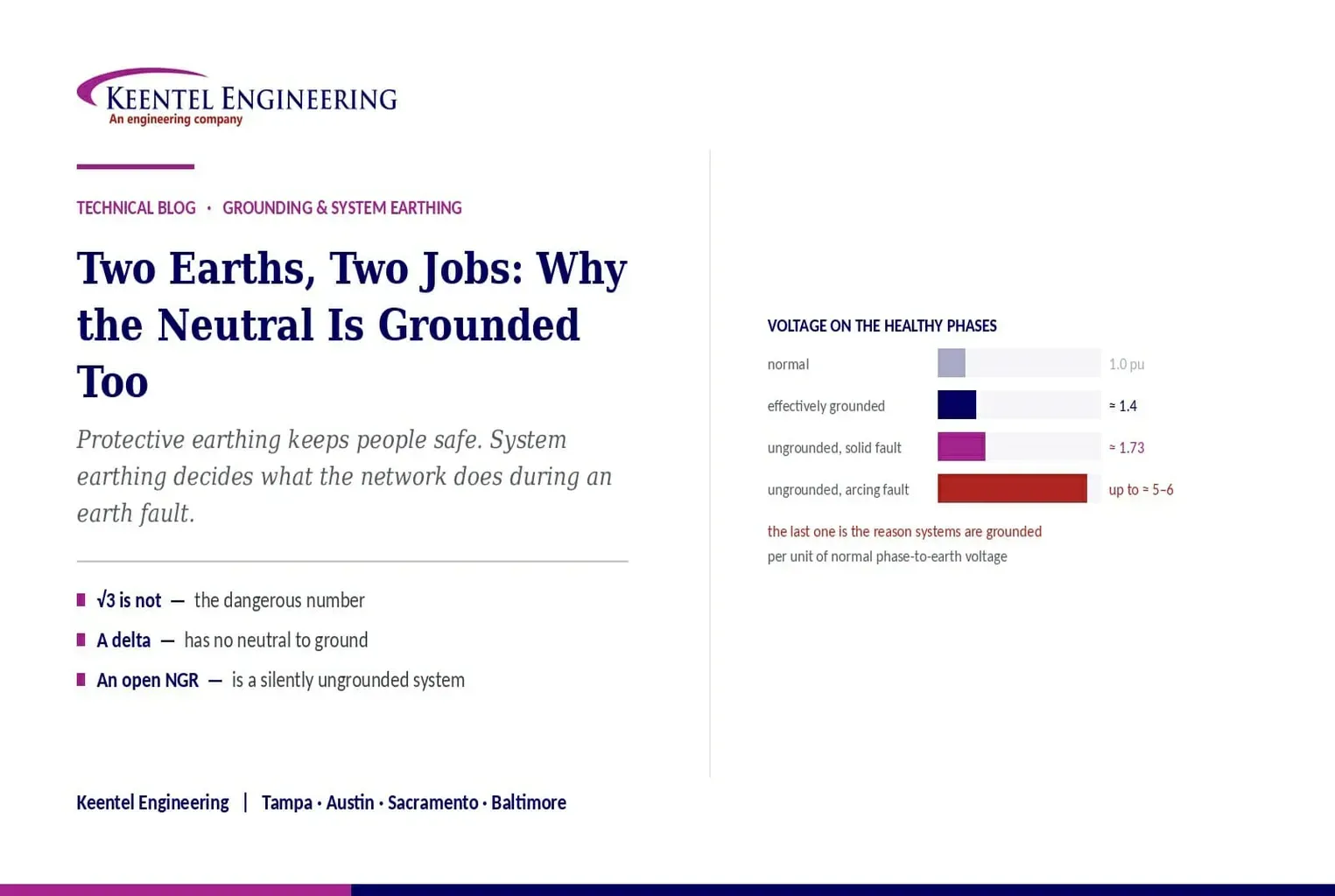
Two Earths, Two Jobs: Why the Neutral Is Grounded Even Though the Tank Already Is
September 7, 2026 | Blog
Protective Earthing Versus System Earthing — What Each Actually Controls, Why the Real Overvoltage Risk Is Not the One Usually Quoted, and Where the Two Decisions Collide on the Same Ground Grid
1. Executive Summary
If a transformer tank is already bonded to the station ground grid, why does the star point also need to be earthed? The question is a good one and it comes up often, because both connections end at the same grid and to a casual eye they look like duplication.
They are not. Body earthing answers the question "what happens to the metalwork and to the person touching it when insulation fails?" Neutral earthing answers the question "what does the electrical system do when a phase touches earth?" Those are different questions with different answers, and satisfying one does not satisfy the other.
The distinction is well made in the material circulating on this subject, and the arithmetic in it is right: on an eleven kilovolt system the normal phase-to-earth voltage is about 6.35 kilovolts, and with a solid earth fault on an ungrounded system the healthy phases rise toward the full line voltage — roughly the square root of three times normal.
What is usually missing is that this is not the dangerous number. A sustained rise of about 1.73 per unit is a tolerable insulation stress on equipment specified for it. The failure mode that actually destroyed ungrounded systems as a general practice is the intermittent arcing ground fault, which can trap charge and restrike repeatedly, producing transient overvoltages several times higher. That mechanism, not the steady-state factor, is why most industrial and utility systems are grounded in some deliberate way.
Three further things belong alongside the two-earths explanation and are absent from it. The formal criterion for effective grounding, which determines surge arrester selection and therefore insulation coordination cost. The fact that a delta winding has no neutral to ground, so a grounding transformer must be provided if one is wanted. And that generator neutral grounding is a different problem from transformer neutral grounding, solved differently, for reasons that have to do with stator iron rather than with system behaviour.
The paper closes with the point that ties the two earths back together: the system grounding decision changes what the ground grid has to achieve, because ground potential rise is the product of the earth fault current and the grid resistance. Choose a heavier grounding method and the grid design gets harder. They are one design problem.
The distinction in one line each
Body earthing controls the voltage a person can be exposed to, and gives protection a path so it clears quickly.
Neutral earthing controls what the whole system does to itself during an earth fault — the fault current, the voltage on the healthy phases, and whether protection can see the fault at all.
2. Two Questions, Not One
It helps to be precise about the vocabulary, because several different things are called earthing and they are not variations of one idea.
| Type | What is connected | What it controls | What it is designed against |
|---|---|---|---|
| Protective earthing — body, tank, frame, enclosure | Exposed conductive parts that are not normally live | Touch voltage on metalwork, and the impedance of the fault return path | Personnel safety and protection operating time |
| System earthing — neutral or star point | A point in the live system, deliberately | Earth fault current magnitude, voltage on healthy phases, and whether earth fault protection can detect anything | System behaviour during an earth fault |
| Lightning protection earthing | Air terminations, masts, shield wires, down conductors | The path for stroke current away from equipment and structures | Direct stroke and its consequences |
| Functional or reference earthing | Instrumentation, control and communications reference points | Signal integrity and reference stability | Electromagnetic interference and measurement error |
| Bonding | Everything conductive, to everything else | Potential differences between adjacent metalwork | Step and touch potential, and static |
All of these may terminate on the same physical grid in a substation, and in modern practice they generally should — separate, isolated electrodes create potential differences between them, which is a hazard rather than a refinement. But sharing a grid does not merge the functions, and the design requirements each imposes on that grid are different.
3. What Body Earthing Actually Does
Bonding a transformer tank or a generator frame to earth does two things, and the usual explanation only names one.
The first is the one everybody knows. If insulation fails and a live conductor contacts the enclosure, the enclosure would otherwise float up toward phase potential. Anyone touching it becomes part of the circuit. Bonding it to the grid holds it close to the potential of the ground the person is standing on, so the voltage across the person is small.
The second matters just as much and is less often stated. The bond provides a low-impedance return path so that enough current flows for the overcurrent or earth fault protection to operate quickly. A high-impedance connection to earth might limit touch voltage under some conditions and still leave the fault current too small to trip anything, in which case the fault persists, the metalwork stays energised, and the failure continues to develop. Touch voltage and clearing time are joined — the accepted touch voltage limits are functions of duration, so a slower clearing time demands a lower voltage.
That is why protective earthing conductors are sized on the fault current and the clearing time, and why the grid design in a substation is analysed against step and touch potential criteria for the actual fault current and the actual protection operating time. It is not a nominal connection; it is a rated conductor with a calculated duty.
4. What Neutral Earthing Actually Does
Connecting the star point to earth — solidly, or through a resistor, reactor or transformer — does four distinct things.
- It fixes the system’s voltage relative to earth. Without it the system floats, and its potential relative to earth is set by the distributed capacitance of the phases, which is a weak and variable reference.
- It creates and sizes the earth fault return path. The magnitude of earth fault current is set almost entirely by this decision — anything from thousands of amperes on a solidly grounded system to single amperes on a high-resistance grounded one.
- It makes earth fault protection possible. Residual and zero-sequence protection detects current that returns through earth. If no such path exists, the quantity the protection measures is negligible and the fault is essentially invisible to it.
- It bounds the voltage on the healthy phases when one phase goes to earth. This is what insulation coordination and surge arrester selection depend on, and it is covered in Sections 5 and 6.
The essential point is that this is a system design decision, not an equipment protection measure. It determines the behaviour of everything connected to that part of the network, and it is made once, deliberately, with consequences for protection, insulation, equipment ratings and the ground grid.
5. The √3 Is Not the Dangerous Number
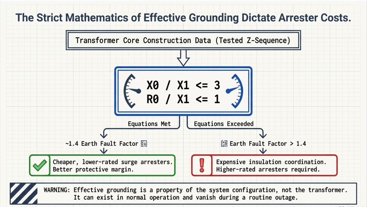
Take the eleven kilovolt example. Normal phase-to-earth voltage is eleven divided by the square root of three, about 6.35 kilovolts. With a solid single phase to earth fault on an ungrounded system, the faulted phase goes to earth potential, the neutral shifts, and the two healthy phases rise to approximately the full line-to-line voltage relative to earth — about eleven kilovolts, or roughly 1.73 times normal.
That arithmetic is correct. It is also a manageable condition. Equipment on ungrounded systems is specified for it, arresters are selected for it, and a system can run in that state while the fault is located. The ability to keep running with one phase down is exactly why ungrounded systems were used, and still are in some continuous-process applications.
The condition that is not manageable is the intermittent arcing earth fault. When the fault is not a solid connection but an arc that extinguishes at a current zero and restrikes as the voltage recovers, charge can be trapped on the system capacitance. Each restrike then begins from an already-elevated starting point, and the process can escalate. Transient overvoltages of several times normal phase-to-earth voltage are the recognised consequence, with values in the region of five to six per unit commonly cited in the literature.
That is the failure mechanism. It does not announce itself, it stresses insulation across the entire galvanically connected system rather than at the fault, and the resulting failures often appear somewhere other than where the arcing was. It is the reason ungrounded operation was abandoned as a general practice, and the reason that where an ungrounded or very lightly grounded system is used today it is accompanied by a deliberate insulation, monitoring and protection philosophy rather than left to chance.
Why this correction matters commercially
A design conversation that frames the risk as "insulation sees 1.73 times normal" invites the answer "then we will specify insulation for 1.73 times normal."
That answer does not address arcing ground overvoltage, ferroresonance, or the difficulty of finding the first fault. Framing the risk correctly is what produces the right grounding decision.
6. Effective Grounding: The Criterion That Decides Your Arresters
There is a formal definition of what counts as adequately grounded, it has a numerical test, and it has a direct cost consequence that surprises people.
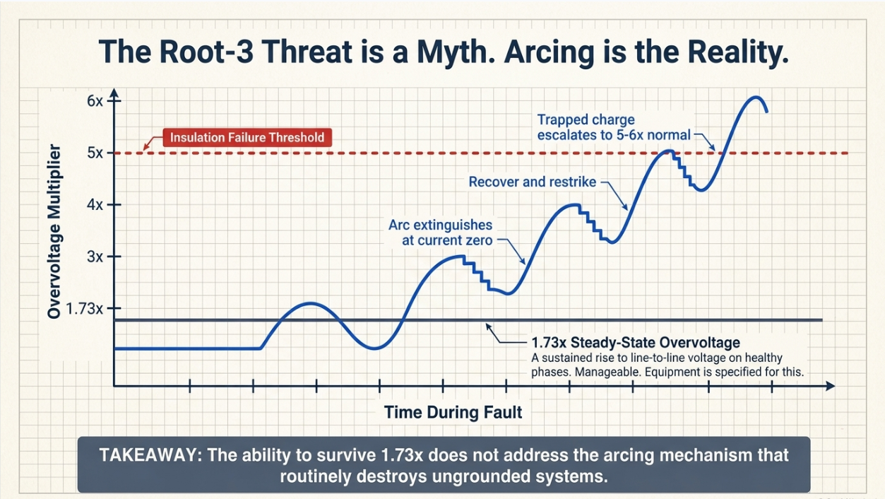
A system is described as effectively grounded when, at the point in question, the ratio of zero-sequence reactance to positive-sequence reactance does not exceed three, and the ratio of zero-sequence resistance to positive-sequence reactance does not exceed one. Where those conditions hold, the voltage on the unfaulted phases during an earth fault is limited to approximately eighty percent of the line-to-line voltage — an earth fault factor of about 1.4 rather than the 1.73 of an ungrounded system.
The consequence is in the arresters. Surge arresters are selected on the continuous operating voltage and on the temporary overvoltage they must survive. On an effectively grounded system, arresters rated at a lower fraction of the system voltage can be used, which gives a better protective margin for the same insulation level, or permits a lower insulation level for the same margin. Where the system is not effectively grounded, arresters must be rated for the higher temporary overvoltage, the protective margin narrows, and insulation coordination becomes more expensive.
Three practical points follow.
- Effective grounding is a property of the system at a point, not a property of a transformer. It depends on the sequence impedances seen there, which depend on which sources are connected, which transformers are in service, and the network configuration. A point can be effectively grounded in one operating state and not in another.
- It has to be calculated, not assumed. This is a sequence impedance calculation using actual transformer zero-sequence data, and the zero-sequence impedance of a transformer is not determinable from its connection diagram alone — core construction matters.
- It is checked at the point of interest and for the credible operating states, including contingency configurations. A generating plant that is a grounding source only when a particular transformer is in service is a common finding.
7. The Grounding Method Spectrum
Solid and resistance grounding are the two the circulating material names. There are more, and the choice is a genuine engineering trade rather than a default.
| Method | Earth fault current | Overvoltage on healthy phases | Operating philosophy | Typical application |
|---|---|---|---|---|
| Solidly grounded | Comparable to three-phase fault current | Lowest — effectively grounded if the impedance ratios are met | Trip immediately. High fault current, so protection is straightforward | Transmission and most distribution; low-voltage systems |
| Low-resistance grounded | Typically limited to hundreds of amperes | Moderate, generally not effectively grounded | Trip on fault. Current limited to reduce equipment damage while remaining easily detectable | Medium-voltage industrial and utility distribution |
| High-resistance grounded | Limited to a few amperes to tens of amperes | Approaches the ungrounded value on the healthy phases | Alarm and locate rather than trip, on the first fault. Requires a fault location process | Continuous-process plants; generator neutrals |
| Reactance grounded | Set by the reactance, between solid and resistance grounded | Depends on the ratio achieved | Used where fault current must be limited but effective grounding is still wanted | Some generator and utility applications |
| Resonant grounded | Very small — the coil is tuned to cancel the capacitive current | Similar to ungrounded on the healthy phases | Arc self-extinguishes; system continues with the fault present | Overhead distribution networks in some markets |
| Ungrounded | Capacitive only, and small | Full line voltage on healthy phases; exposed to arcing ground transients | Continue running and locate the fault, with monitoring | Legacy and specific continuous-process applications |
The trade running through the table is between fault current and voltage stress. Reduce the earth fault current and you reduce equipment damage, arc flash energy on earth faults and ground potential rise — but you raise the voltage on the healthy phases, make detection harder, and lose effective grounding. Raise it and you get the opposite. There is no method that is best on every axis, which is why the decision has to be made against the specific installation and stated in the design basis.
8. You Cannot Ground a Delta
An assumption sits underneath the whole discussion and it is worth surfacing: that there is a neutral available to ground. Frequently there is not.
A delta winding has no star point. There is nothing to connect to earth, and a system fed from a delta winding is ungrounded unless something else grounds it. That is not a defect in the transformer; it is a property of the connection, and it is extremely common — the delta side of a delta / grounded-wye transformer, the tertiary of a three-winding unit, and the collector side of many generating plant arrangements.
Where a grounding reference is wanted on such a system, it has to be created deliberately, with a grounding transformer. The two usual arrangements are a zigzag transformer, which presents a low zero-sequence impedance path by construction, and a wye-delta grounding bank, where the delta provides the ampere-turn balance. Either way the device is a designed component with its own ratings, and the ratings are not obvious.
- Zero-sequence impedance, which sets the earth fault current and therefore whether the system is effectively grounded.
- Continuous rating, for the unbalance current it will carry in normal operation.
- Short-time thermal rating, for the fault current it must survive for the clearing time — typically a ten-second or one-minute rating rather than a continuous one, which is why grounding banks look small for their duty.
- Its own protection, because a grounding bank that fails open silently removes the grounding reference from the system, which is the failure mode in Section 12.
The related point is that a transformer’s zero-sequence behaviour is not readable from its winding connection alone. For a grounded-wye / grounded-wye transformer without a delta, the zero-sequence impedance depends on core construction — a three-legged core-form unit behaves quite differently from a shell-form or five-legged design with the same nameplate. Any effective grounding calculation needs the tested zero-sequence impedance, not an assumed one.
9. Generators Are a Different Problem
The circulating material treats transformer neutrals and generator neutrals as the same subject. They share a name and very little else, and the difference is worth understanding because it explains a practice that otherwise looks inconsistent.
On a transformer, the grounding method is chosen to control system behaviour. On a generator, the dominant consideration is the machine itself. A stator earth fault passes current through the stator core iron, and iron damage from that current is expensive and slow to repair — potentially requiring a rewind or core restack. The damage is a strong function of fault current magnitude, so the design objective is to limit stator earth fault current to a very low value.
The usual arrangement is high-resistance grounding through a distribution transformer with a resistor on its secondary. The transformer steps the neutral voltage down so that a modestly sized secondary resistor reflects as a very high effective primary resistance, limiting the earth fault current to a few amperes. That is enough for protection to detect the fault and far too little to damage the core.
Two consequences follow.
- The generator sits in its own grounding zone. It is normally connected to the system through a delta winding on the step-up transformer, which isolates the generator zero-sequence network from the system entirely. The generator can be high-resistance grounded while the system beyond the transformer is solidly grounded, and neither affects the other. That is by design and it is a good illustration of Section 8 in practice.
- Detecting faults near the neutral requires special methods. A conventional neutral overvoltage element sees very little for a fault close to the star point, because the voltage there is small. Achieving coverage of the full winding requires third-harmonic-based or injection-based schemes, which is why hundred-percent stator earth fault protection is a distinct and non-trivial function.
So the answer to "why is the generator neutral grounded through a resistor when the transformer next to it is solidly grounded?" is that they are solving different problems, in electrically separate zones.
10. Where the Two Systems Interact
Having separated the two functions, the paper should now put them back together, because the most consequential engineering point is the place they meet.
Ground potential rise is the product of the current returning through the grid and the grid’s resistance to remote earth. Step and touch potentials — the criteria the grid design has to satisfy — scale with that rise. So the earth fault current, which is set by the system grounding decision, is a direct input to the grid design.
The interaction runs in both directions and is worth stating plainly.
- Choose solid grounding and the earth fault current is high, which is good for protection and detection, and makes step and touch potential harder to satisfy. The grid needs more conductor, more rods, possibly surface treatment, and in poor soil that can become a substantial cost.
- Choose resistance grounding and the earth fault current is low, ground potential rise falls with it, and the grid design gets easier — but detection is harder, effective grounding may be lost, and the healthy phases see more voltage.
- Change the system grounding later — add a source, change a transformer connection, add a grounding bank — and the grid analysis is invalidated. A grid designed against one fault current is not automatically adequate for a higher one.
Both calculations also depend on the protection clearing time, which is a third discipline’s decision. The permissible touch voltage falls as duration rises, and the conductor thermal rating depends on the same duration. So system grounding, grid design and protection settings are one coupled problem, routinely solved by three different people at three different times.
11. One Bond, Not Several
There is a rule that follows from the distinction between the two earthing functions and is broken constantly in the field.
The neutral is bonded to earth at one point per separately derived system. Not at the transformer and again at the switchboard; not at every panel; once.
The reason is that a neutral conductor carries current in normal operation on a system serving unbalanced or single-phase load. If the neutral is bonded to earth at more than one point, that normal neutral current divides between the neutral conductor and every parallel path through the earthing system — the grid, the building steel, cable armour, conduit, piping. The consequences are real and cumulative.
- Current flows continuously through structural steel and equipment enclosures that were never intended to carry it.
- Ground fault protection sees a standing residual current that has nothing to do with a fault, which either causes nuisance operation or forces the sensitivity to be relaxed until the protection no longer does its job.
- Potential differences appear between points of metalwork, producing stray voltage and measurable interference in instrumentation and communications.
- Corrosion accelerates where the current enters and leaves buried metalwork.
The diagnostic is straightforward when someone thinks to do it: with the system energised and carrying normal load, measure current on the bonding conductors. A protective bonding conductor should carry essentially nothing under healthy conditions. If it is carrying steady current proportional to load, there is a second neutral-to-earth bond somewhere, and finding it is a survey rather than a calculation.
12. The Neutral Earthing Resistor Is a Component That Fails
A resistance-grounded system depends on a resistor. Resistors fail, and the failure mode that matters is the silent one.
If a neutral earthing resistor fails open — or its connection fails, or an isolating link is left open after maintenance — the system is no longer resistance grounded. It is ungrounded. Nothing about normal operation changes: the load is unaffected, voltages look normal, and nothing alarms unless something was specifically arranged to alarm.
The system then sits in the condition described in Section 5, exposed to arcing ground overvoltage, with its earth fault protection unable to see a first fault because there is no return path for the current the protection is looking for. The consequences appear when the first earth fault occurs, which may be months later, and the failure is frequently attributed to whatever equipment happened to fail rather than to the missing resistor.
The engineering responses are inexpensive relative to the exposure.
- Continuity monitoring on the neutral earthing path, alarmed to somewhere a person will act on it. This is the single most valuable measure and it is frequently omitted.
- Periodic testing of the resistor value and the integrity of the connection, as a scheduled maintenance activity with a recorded result rather than a visual inspection.
- Isolating links treated as a controlled item, with the position verified and recorded after any work on the neutral connection.
- Neutral displacement monitoring, which detects the neutral shift characteristic of an earth fault whether or not the resistor is intact, and which provides an independent indication.
The same reasoning applies to a grounding transformer. A grounding bank that has been isolated, has failed, or has had its protection operate without anyone noticing leaves the system ungrounded in exactly the same way.
13. Case Studies
The following scenarios are composite and illustrative. They are constructed from patterns that recur across industrial and utility systems to show how these failures develop and how they are found. They do not describe any specific client, site, project, manufacturer, or utility.
13.1 Case A — The System That Had Quietly Become Ungrounded
Situation. A medium-voltage distribution system at an industrial facility, designed as low-resistance grounded with earth fault protection set to detect and clear faults on the resistor-limited current. The system had operated without incident for a number of years.
What happened
A phase-to-earth fault developed on a cable. It did not clear. Over a period, insulation failures appeared at several unrelated locations on the same galvanically connected system, including equipment remote from the original fault and equipment that had no history of problems.
What the investigation found
The neutral earthing resistor connection had been opened during maintenance work some time earlier and not restored. The system had been operating ungrounded. The first earth fault therefore drew only capacitive current, well below the earth fault protection setting, and was never detected. Because the fault was intermittent rather than solid, the system had been subjected to repeated arcing ground transients, stressing insulation across the whole network. The failures that eventually appeared were the weakest points in that population, not the fault location.
Why it was hard to see
Nothing in normal operation indicated a problem. Load was unaffected, phase voltages measured normally under healthy conditions, and no alarm existed for loss of the neutral earthing path. The condition was invisible until it caused damage, and the damage appeared to be unrelated equipment failures.
Remedy
The resistor connection was restored and tested. Continuity monitoring of the neutral earthing path was added with an alarm to the control room. Neutral displacement monitoring was installed to provide independent indication of an earth fault. Isolating links in the neutral path were added to the controlled-item register with position verification required after any work.
Lesson
A resistance-grounded system depends on a component, and that component can fail in a way that changes the entire system’s behaviour without changing anything observable. If there is no monitoring on the neutral earthing path, the design has an undetectable single point of failure at its foundation.
13.2 Case B — Arresters Selected on a Grounding Assumption That Was Not True
Situation. A substation serving a generating installation, with surge arresters selected on the basis that the system was effectively grounded permitting a lower arrester rating and a correspondingly better protective margin against the equipment insulation level.
What happened
Arrester failures occurred over a period, at more than one location, without an obvious lightning or switching cause coinciding with them.
What the investigation found
The effective grounding assessment had been performed for the normal system configuration, in which a particular transformer provided the grounding reference. In several credible operating configurations including a routine outage of that transformer the point was no longer effectively grounded. The impedance ratios exceeded the criterion, the temporary overvoltage during an earth fault exceeded what the arresters were rated to withstand, and the arresters absorbed energy they were never selected for.
A contributing factor
The zero-sequence impedance used in the original assessment had been taken from a typical value rather than from the transformer test report. The actual tested value differed enough to matter, which is a recurring issue for wye-wye transformers where core construction rather than the connection diagram governs the zero-sequence behaviour.
Remedy
The effective grounding assessment was repeated across the credible operating configurations using tested zero-sequence data, arrester ratings were revised for the worst case rather than the normal case, and operating instructions were revised so that configurations that removed the grounding source were identified and managed.
Lesson
Effective grounding is a property of the system at a point in a configuration, not a property of an installation. Assessing it only in the normal configuration, with assumed impedance data, produces an arrester selection that is correct most of the time and inadequate exactly when it is needed.
13.3 Case C — The Ground Fault Relay That Would Not Stay Set
Situation. A low-voltage distribution system in a facility with substantial single-phase load. Ground fault protection had been progressively desensitised over several years because it operated on load changes that were not faults, until eventually it was set so high that it provided little useful protection.
What the investigation found
The neutral was bonded to earth at more than one point. In addition to the correct bond at the source, a second bond existed at a downstream distribution board, created during an earlier modification. Normal neutral current was therefore dividing between the neutral conductor and parallel paths through the building steel and the earthing system, and the residual quantity the ground fault protection measured included a standing component proportional to load rather than only fault current.
What else it was causing
Measurable potential differences between points of building metalwork, intermittent noise on instrumentation and communications circuits sharing routes with the affected steel, and evidence of accelerated corrosion where the stray current entered and left buried metalwork. None of these had previously been connected to the protection problem, and each had been investigated separately.
Remedy
A bonding survey located and removed the additional bond. Neutral-to-earth continuity was verified as a single point per separately derived system. Ground fault protection was reset to appropriate sensitivity and verified against measured residual current under load. The single-point bonding requirement was written into the facility’s modification procedure so that future work would not recreate it.
Lesson
A ground fault relay that keeps operating without a fault is reporting something real. Desensitising it removes the symptom and the protection at the same time. The underlying condition also produces stray voltage, interference and corrosion, which are usually investigated as unrelated problems by different people.
14. Reading the Source Correctly
The core distinction is right and well put
Body earthing protects people and metalwork; neutral earthing determines how the system behaves during an earth fault. Both may terminate on the same grid and their purposes are different. That is the correct framing and it is the answer to the question as asked.
The arithmetic is right, and it is not the dangerous number
Eleven divided by the square root of three is about 6.35 kilovolts, and healthy phases approaching eleven kilovolts on an ungrounded system is a factor of 1.73. Correct — and that sustained condition is manageable. The mechanism that actually matters is the intermittent arcing earth fault and the much higher transient overvoltages it can produce.
Effective grounding has a numerical definition and a cost
Zero-sequence to positive-sequence reactance ratio not exceeding three, and zero-sequence resistance to positive-sequence reactance not exceeding one. Meeting it limits the earth fault factor to about 1.4 and permits lower-rated arresters. Failing it makes insulation coordination more expensive. It is calculated, it is configuration-dependent, and it needs tested transformer data.
Not every winding has a neutral to ground
A delta winding has no star point. Systems fed from one are ungrounded unless a grounding transformer is provided, and that device has zero-sequence impedance, continuous, short-time and protection requirements of its own.
Generators are a separate problem
Generator neutral grounding is driven by stator core damage rather than system behaviour, which is why high-resistance grounding limiting the fault to a few amperes is the normal answer, and why the generator sits in its own grounding zone behind the step-up transformer delta.
The two earths meet at ground potential rise
The system grounding decision sets the earth fault current, which with the grid resistance sets ground potential rise, which is what the step and touch potential criteria are evaluated against. Heavier grounding makes protection easier and the grid harder. They are one design problem, and the clearing time is an input to both.
15. Keentel Grounding and System Earthing Services
Grounding and system earthing sit at the intersection of protection, insulation coordination and personnel safety, which is why they are so often designed in pieces. Keentel Engineering treats them as one problem.
15.1 System Grounding Design
- System grounding method selection against the specific installation — solid, low-resistance, high-resistance, reactance or resonant — with the trade between fault current, overvoltage, detectability and continuity of operation documented in the design basis.
- Effective grounding assessment using tested transformer zero-sequence data, evaluated across the credible operating configurations rather than the normal one only.
- Neutral earthing resistor and reactor specification including resistance value, continuous and short-time ratings, and monitoring requirements.
- Grounding transformer specification and sizing — zigzag or wye-delta — with zero-sequence impedance, continuous unbalance rating, short-time thermal rating and protection.
- Generator neutral grounding design, including distribution transformer and secondary resistor sizing and coordination with stator earth fault protection.
15.2 Ground Grid and Safety
- Substation grounding grid design from measured soil resistivity, with ground potential rise, step and touch potential analysis against the actual earth fault current and protection clearing time.
- Conductor and connection sizing for thermal duty, and evaluation of existing grids against revised fault levels where the system has changed.
- Protective earthing and bonding design, single-point bonding verification, and stray current and circulating current investigation.
- Lightning protection and shielding design, and coordination of the lightning, protective, system and functional earthing arrangements onto one grid.
15.3 Insulation Coordination and Protection
- Insulation coordination studies, surge arrester selection against continuous operating voltage and temporary overvoltage for the worst credible grounding configuration, and protective margin verification.
- Earth fault and zero-sequence protection design and settings, including sensitive earth fault, neutral displacement, restricted earth fault and hundred-percent stator earth fault schemes.
- Short-circuit, protective coordination and arc-flash studies, with the earth fault case evaluated rather than assumed to be bounded by the phase fault case.
- Current transformer sizing and saturation assessment for earth fault applications, where the quantities are small and accuracy matters most.
15.4 Investigation, Assessment, and Owner’s Engineer Support
- Investigation of arrester failures, repeated insulation failures, nuisance ground fault operation, stray voltage and interference problems.
- Condition assessment of existing grounding installations, including verification that the system is grounded the way the drawings say it is.
- Design review of third-party grounding studies and packages, and QA/QC of soil resistivity data and grid models.
- Commissioning specification and test procedures including grid integrity, resistance measurement, neutral earthing path continuity and protection verification.
Keentel Engineering holds a Florida Certificate of Authorization and maintains offices in Tampa, Austin, Sacramento, and Baltimore, supporting projects across the interconnections.
16. References and Further Reading
The following are referenced by subject in the body of this document. The current published edition of each standard governs its own requirements, and the edition adopted by the authority having jurisdiction governs code requirements.
System Grounding
- IEEE Std 142, Recommended Practice for Grounding of Industrial and Commercial
Power Systems
the Green Book, covering system grounding method selection, equipment grounding and the grounding of sensitive electronic equipment — IEEE Standards Association
- IEEE Std C62.92 series, Guide for the Application of Neutral Grounding in Electrical Utility Systems — including the effective grounding criteria and the treatment of generator and distribution system grounding — IEEE Standards Association
- IEEE Std C37.101 for generator ground protection and IEEE Std C37.102 for generator protection, covering stator earth fault schemes including hundred-percent coverage methods — IEEE Standards Association
- IEEE Std C57.32 for neutral grounding devices, covering grounding transformers, neutral earthing resistors and reactors and their rating requirements — IEEE Standards Association
Ground Grid, Safety, and Bonding
- IEEE Std 80, Guide for Safety in AC Substation Grounding — ground potential rise, step and touch potential criteria, and grid design — IEEE Standards Association
- IEEE Std 81, Guide for Measuring Earth Resistivity, Ground Impedance, and Earth Surface Potentials of a Grounding System, and IEEE Std 837 for permanent connections — IEEE Standards Association
- NFPA 70, National Electrical Code — including the article covering grounding and bonding, separately derived systems and the single-point bonding requirement — National Fire Protection Association
- ANSI C2, National Electrical Safety Code, for grounding requirements applicable to electric supply stations and lines — Institute of Electrical and Electronics Engineers
Insulation Coordination and Overvoltage
- IEEE Std 1313.1 and IEEE Std 1313.2, Standard and Application Guide for Insulation Coordination, covering temporary overvoltage and the relationship to system grounding — IEEE Standards Association
- IEEE Std C62.11 for metal-oxide surge arresters and IEEE Std C62.22 for their application, including selection against continuous operating voltage and temporary overvoltage — IEEE Standards Association
- IEC 60071 series, Insulation co-ordination, including the earth fault factor and its relationship to the neutral earthing arrangement — International Electrotechnical Commission
17. Frequently Asked Questions
Q1. If the tank is already earthed, why earth the neutral as well?
Because they answer different questions. Body earthing controls the voltage on metalwork a person can touch and gives protection a low-impedance return path so it operates quickly. Neutral earthing controls what the electrical system does during an earth fault — the fault current, the voltage on the healthy phases, and whether earth fault protection can see anything at all.
Q2. They both end at the same grid. Does that not make them the same?
Sharing a grid does not merge the functions. Each imposes different requirements on that grid — different conductor duties, different fault currents, different analysis. In modern practice they should share one grid, because separate isolated electrodes create dangerous potential differences between them.
Q3. What does body earthing actually do, precisely?
Two things. It holds exposed metalwork close to the potential of the ground the person is standing on, so the voltage across a person is small. And it provides a low-impedance path so enough current flows for protection to operate quickly. Both matter, because permissible touch voltage falls as the fault duration rises.
Q4. What does neutral earthing do?
Four things: it fixes the system voltage relative to earth; it creates and sizes the earth fault return path; it makes residual and zero-sequence protection possible by giving that protection something to measure; and it bounds the voltage that appears on the healthy phases during an earth fault.
Q5. What happens on an ungrounded system when one phase faults to earth?
The faulted phase goes to earth potential, the neutral shifts, and the two healthy phases rise toward the full line-to-line voltage relative to earth — about 1.73 times normal phase-to-earth. On an eleven kilovolt system, from about 6.35 kilovolts to about eleven.
Q6. Is that 1.73 factor the main danger?
No, and this is the correction worth making. A sustained rise of 1.73 per unit is manageable, and equipment on ungrounded systems is specified for it. The dangerous mechanism is the intermittent arcing earth fault, where the arc extinguishes and restrikes repeatedly, trapping charge and escalating. Transient overvoltages of several times normal are the recognised consequence, commonly cited in the region of five to six per unit.
Q7. Why does that matter for the design conversation?
Because framing the risk as "insulation sees 1.73 times normal" invites the answer "specify insulation for 1.73 times normal." That does not address arcing ground overvoltage, ferroresonance, or the difficulty of finding the first fault. The framing determines whether the right grounding decision gets made.
Q8. Are ungrounded systems wrong?
Not inherently, and they exist for a good reason — the ability to keep operating with one phase faulted is valuable in continuous processes. But they require a deliberate insulation, monitoring and fault-location philosophy, and a documented process for finding and clearing the first fault rather than living with it.
Q9. What is effective grounding?
A defined condition: at the point in question, the zero-sequence to positive-sequence reactance ratio does not exceed three and the zero-sequence resistance to positive-sequence reactance ratio does not exceed one. Where it holds, the voltage on unfaulted phases during an earth fault is limited to about eighty percent of line-to-line — an earth fault factor near 1.4 rather than 1.73.
Q10. Why does effective grounding matter commercially?
Arresters. On an effectively grounded system, arresters rated at a lower fraction of system voltage can be used, giving a better protective margin for the same insulation level or permitting a lower insulation level for the same margin. Where it is not met, arresters must be rated higher, the margin narrows, and insulation coordination gets more expensive.
Q11. Can a system be effectively grounded some of the time?
Yes, and this is a common finding. Effective grounding depends on the sequence impedances seen at a point, which depend on which sources and transformers are in service. A point can meet the criterion in the normal configuration and fail it during a routine outage. It has to be assessed across the credible configurations.
Q12. Can I determine zero-sequence impedance from the transformer connection?
Not reliably. For a grounded-wye to grounded-wye transformer without a delta, the zero-sequence impedance depends on core construction — a three-legged core-form unit behaves very differently from a shell-form or five-legged design with the same nameplate. Use the tested value from the factory test report.
Q13. What are the grounding methods and how do they differ?
Solid, low-resistance, high-resistance, reactance, resonant and ungrounded. The trade running through all of them is fault current against voltage stress: less earth fault current means less equipment damage, less arc energy and lower ground potential rise, but harder detection, more voltage on the healthy phases and possible loss of effective grounding.
Q14. What if the winding is a delta?
Then there is no star point and nothing to ground. Systems fed from a delta winding are ungrounded unless a grounding transformer is provided — typically a zigzag or a wye-delta bank — which is a designed component with zero-sequence impedance, continuous and short-time ratings, and its own protection.
Q15. Why is a grounding bank rated for short time rather than continuously?
Because it carries substantial current only during a fault, for the clearing time. A typical rating is expressed over ten seconds or a minute, which is why grounding banks look physically small for the fault duty they handle. They also need a continuous rating for the normal unbalance current.
Q16. Why are generator neutrals usually high-resistance grounded?
Because the dominant concern is the machine, not the system. A stator earth fault passes current through the core iron and the damage scales strongly with current — potentially requiring a rewind or core restack. High-resistance grounding through a distribution transformer with a secondary resistor limits the fault to a few amperes, enough to detect and too little to damage the core.
Q17. How can a generator be high-resistance grounded when the system beyond is solidly grounded?
Because they are separate zero-sequence zones. The generator step-up transformer normally has a delta winding on the generator side, which isolates the two zero-sequence networks entirely. Each zone is grounded for its own reasons and neither affects the other.
Q18. Why is stator earth fault protection near the neutral difficult?
Because the voltage at the star point is small, so a fault close to it produces very little neutral displacement for a conventional element to detect. Covering the full winding requires third-harmonic-based or injection-based schemes, which is why hundred-percent stator earth fault protection is a distinct function rather than a setting.
Q19. How do the two earthing systems interact?
Through ground potential rise, which is the current returning through the grid multiplied by the grid resistance. Step and touch potentials scale with it. So the system grounding decision, which sets the earth fault current, is a direct input to the ground grid design — heavier grounding makes protection easier and the grid harder.
Q20. What happens if the system grounding changes later?
The grid analysis is invalidated. A grid designed against one earth fault current is not automatically adequate for a higher one. Adding a source, changing a transformer connection or adding a grounding bank all change the fault current and require the step and touch potential analysis to be repeated.
Q21. Why must the neutral be bonded to earth at only one point?
Because a neutral carries current in normal operation on any system with unbalanced or single-phase load. With more than one bond, that normal current divides between the neutral conductor and parallel paths through the grid, building steel, armour and conduit — producing standing residual current, nuisance ground fault operation, stray voltage, interference and accelerated corrosion.
Q22. How do I test for a second neutral-to-earth bond?
With the system energised and carrying normal load, measure current on the bonding conductors. A protective bonding conductor should carry essentially nothing under healthy conditions. Steady current proportional to load indicates a second bond, and locating it is a survey rather than a calculation.
Q23. What is the risk if a neutral earthing resistor fails open?
The system becomes ungrounded, silently. Load is unaffected, voltages look normal under healthy conditions, and nothing alarms unless something was specifically arranged to alarm. The system is then exposed to arcing ground overvoltage, and earth fault protection cannot see a first fault because there is no return path for the current it measures.
Q24. How is that risk managed?
Continuity monitoring on the neutral earthing path, alarmed somewhere a person will act on it — the single most valuable measure and frequently omitted. Plus periodic testing of the resistor value with a recorded result, isolating links treated as controlled items with position verified after any work, and neutral displacement monitoring as an independent indication.
Q25. What is the one habit worth adopting?
Write the system grounding method, the resulting earth fault current, the effective grounding assessment and the clearing time into the design basis, together — and treat any change to one of them as a trigger to revisit the grid analysis, the arrester selection and the protection settings. They are one coupled problem routinely solved by three people at three different times.
Notice and Disclaimer
This document is original technical content prepared by Keentel Engineering LLC for general professional information. It is not project-specific engineering advice and does not constitute a design, a study, an equipment specification, or a safety determination for any installation. System grounding method selection, ground grid design, insulation coordination and protection settings must be established by project-specific analysis using measured soil data, tested equipment impedance data, and the applicable code and utility requirements.
Values, ratios and behavioural descriptions in this paper are general engineering discussion. Actual overvoltage magnitudes, fault currents, ratings and grounding requirements vary with system configuration, equipment characteristics and operating condition, and must be established from calculation and from the applicable standards rather than inferred from typical figures.
The case studies in Section 13 are composite and illustrative. They are constructed from patterns that recur across the industry to demonstrate how these failures develop and how they are found. They do not describe any specific client, site, project, manufacturer, or utility, and no inference should be drawn about any actual installation or party.
Work on or near neutral earthing equipment carries specific hazards, including the possibility that a neutral conductor is at elevated potential during a fault. All such work must be carried out under an appropriate safe system of work by qualified persons.
Keentel Engineering LLC is an independent engineering consultancy. Reference to any standard, code, industry organisation, regulator, or equipment category in this document does not imply affiliation with, endorsement by, or sponsorship from any such organisation or manufacturer.

About the Author:
Sandip "Sonny" R. Patel, P.E.
IEEE Senior Member · Founder & CEO, Keentel Engineering
In 1995, Sonny Patel earned his Electrical Engineering degree from the University of Illinois. But degrees don't build legacies — action does.
For three decades, he has worked the power industry from every side of the table: 16 years as a utility engineer at Exelon/Commonwealth Edison; generation leadership across hydroelectric, industrial steam turbine, and a 9 GW renewable fleet; NERC Regional Entity Senior Compliance Engineer and Audit Team Lead, auditing some of the nation's largest utilities; and testing and commissioning lead on equipment up to 765 kV — the very top of the North American grid.Utility. Generator. Regulator. Consultant. Few engineers have seen all four seats. Fewer still have sat in them.
His experience spans nuclear, hydro, conventional generation, renewables, oil and gas, mining — and today's data centers, where he is authoring a three-book series on data center design. He is a Licensed Professional Engineer in six states and a Licensed Electrical Contractor in Florida (Unlimited EC) — he doesn't just design the work; he's qualified to stand behind its execution.Today, as Founder and CEO of Keentel Engineering, Sonny leads a nationwide team of engineers delivering substation design, power system studies, NERC compliance, and commissioning — done right, coast to coast.Three decades. Every side of the table. One standard: accountable engineering.
Services

Let's Discuss Your Project
Let's book a call to discuss your electrical engineering project that we can help you with.
About the Author:
Sandip "Sonny" R. Patel, P.E.
IEEE Senior Member · Founder & CEO, Keentel Engineering
In 1995, Sonny Patel earned his Electrical Engineering degree from the University of Illinois. But degrees don't build legacies — action does.
For three decades, he has worked the power industry from every side of the table: 16 years as a utility engineer at Exelon/Commonwealth Edison; generation leadership across hydroelectric, industrial steam turbine, and a 9 GW renewable fleet; NERC Regional Entity Senior Compliance Engineer and Audit Team Lead, auditing some of the nation's largest utilities; and testing and commissioning lead on equipment up to 765 kV — the very top of the North American grid.
Utility. Generator. Regulator. Consultant. Few engineers have seen all four seats. Fewer still have sat in them.
His experience spans nuclear, hydro, conventional generation, renewables, oil and gas, mining — and today's data centers, where he is authoring a three-book series on data center design. He is a Licensed Professional Engineer in six states and a Licensed Electrical Contractor in Florida (Unlimited EC) — he doesn't just design the work; he's qualified to stand behind its execution.
Today, as Founder and CEO of Keentel Engineering, Sonny leads a nationwide team of engineers delivering substation design, power system studies, NERC compliance, and commissioning — done right, coast to coast.Three decades. Every side of the table. One standard: accountable engineering.
Leave a Comment
Thank you for contacting us.
We will get back to you as soon as possible.
We will get back to you as soon as possible.
Oops, there was an error sending your message.
Please try again later.
Please try again later.
Related Posts
By SANDIP R PATEL
•
October 23, 2026
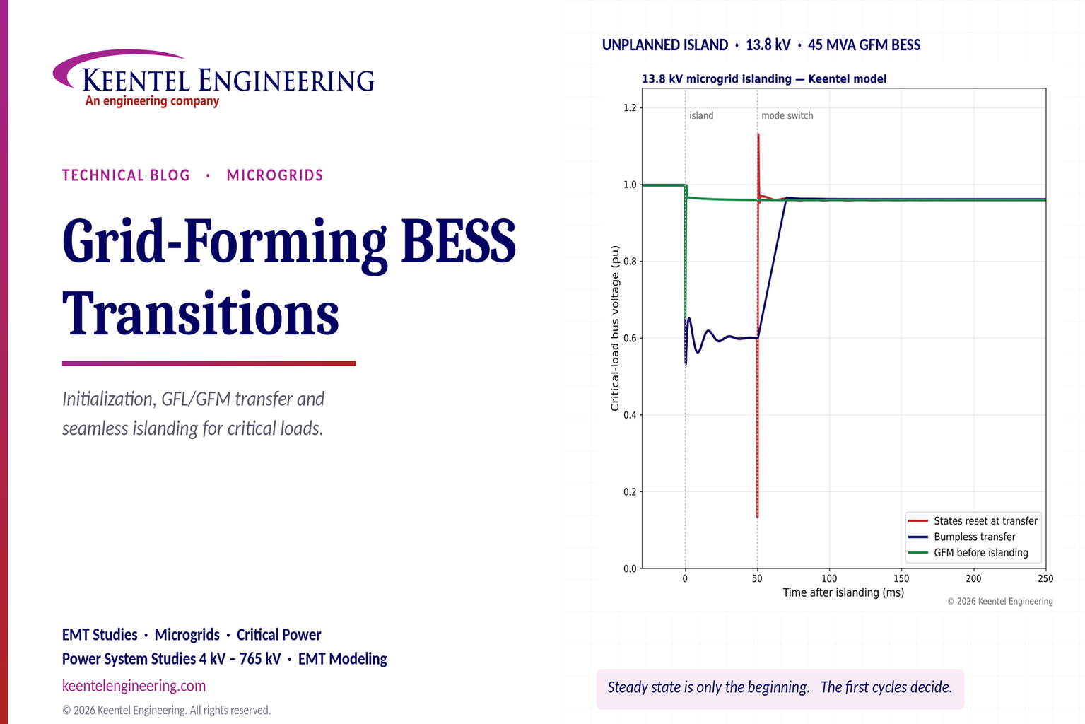
Explore grid-forming BESS initialization, GFL-to-GFM transitions, seamless islanding, EMT simulations, current limiting and microgrid protection.
By SANDIP R PATEL
•
October 23, 2026
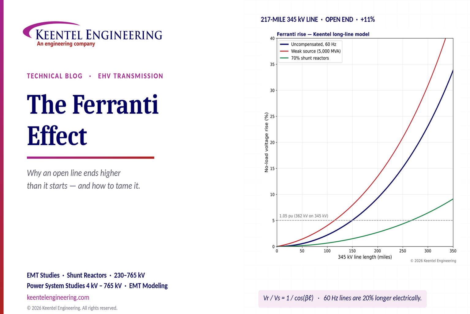
Explore the Ferranti effect in EHV transmission lines: voltage rise, 345 kV examples, switching overvoltages, shunt reactor sizing and mitigation.
By SANDIP R PATEL
•
October 23, 2026
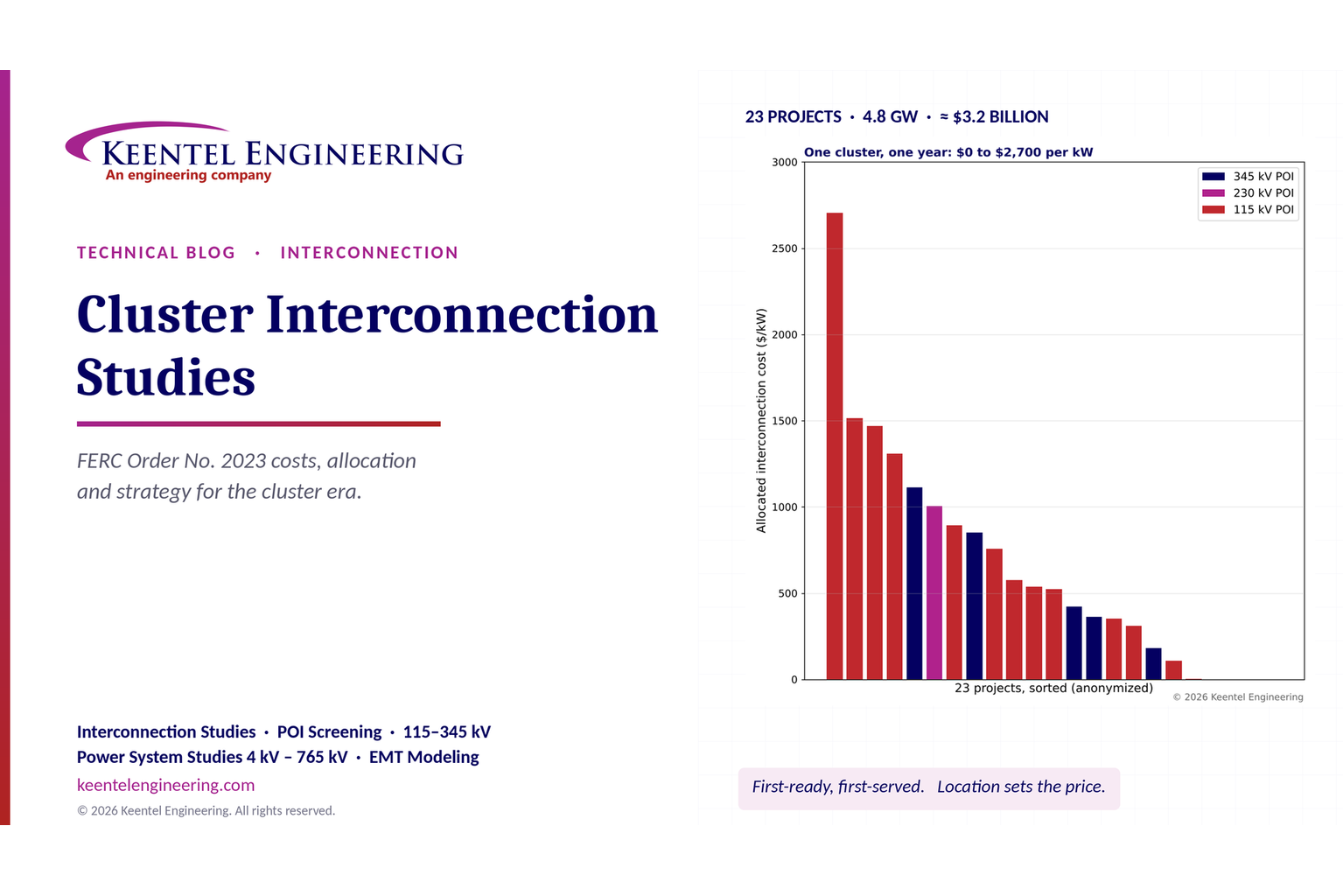
Explore cluster interconnection studies under FERC Order 2023, including network upgrades, cost allocation, withdrawal penalties and developer strategy.
By SANDIP R PATEL
•
October 21, 2026
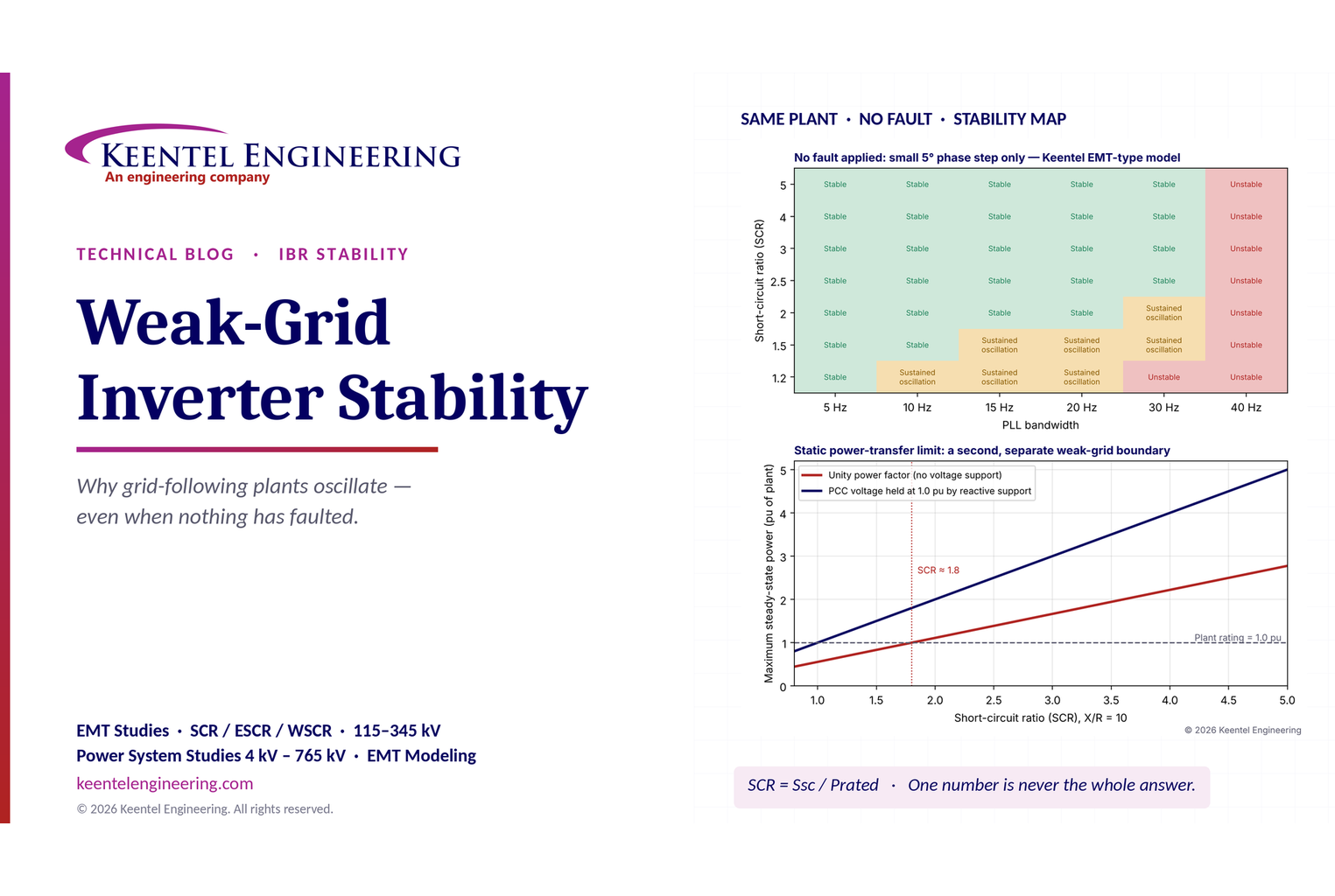
Learn why grid-following inverters become unstable without grid faults. Explore SCR, PLL interactions, EMT studies, grid strength, and mitigation.
By SANDIP R PATEL
•
October 21, 2026
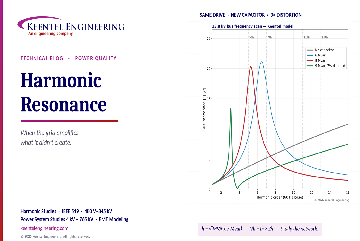
Learn how harmonic resonance amplifies distortion in power systems. Explore capacitor banks, detuned reactors, frequency scans, and IEEE 519 solutions.
By SANDIP R PATEL
•
October 20, 2026
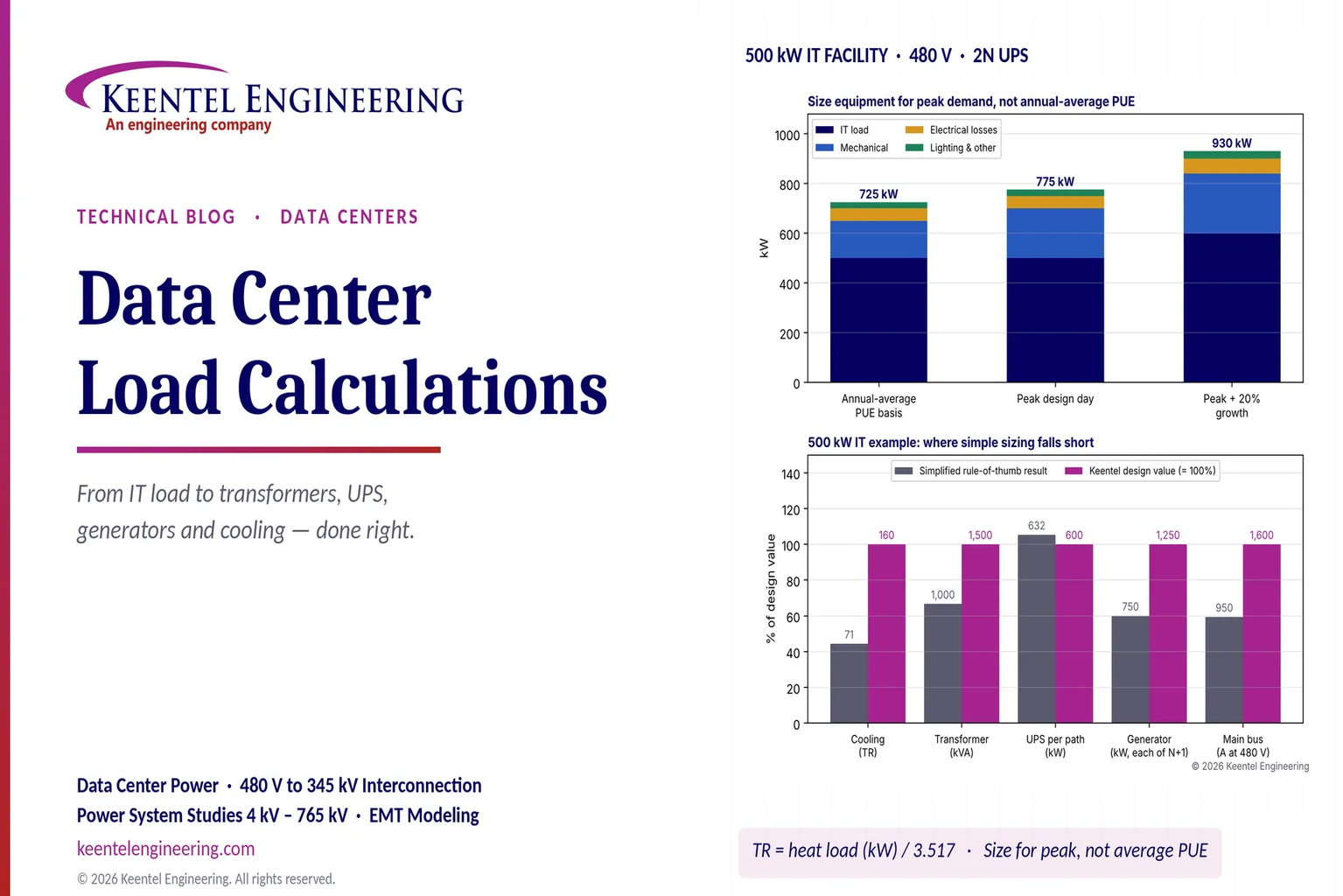
Learn data center electrical load calculations, including IT demand, PUE, UPS and generator sizing, cooling loads, redundancy, and worked US examples.
By SANDIP R PATEL
•
October 20, 2026
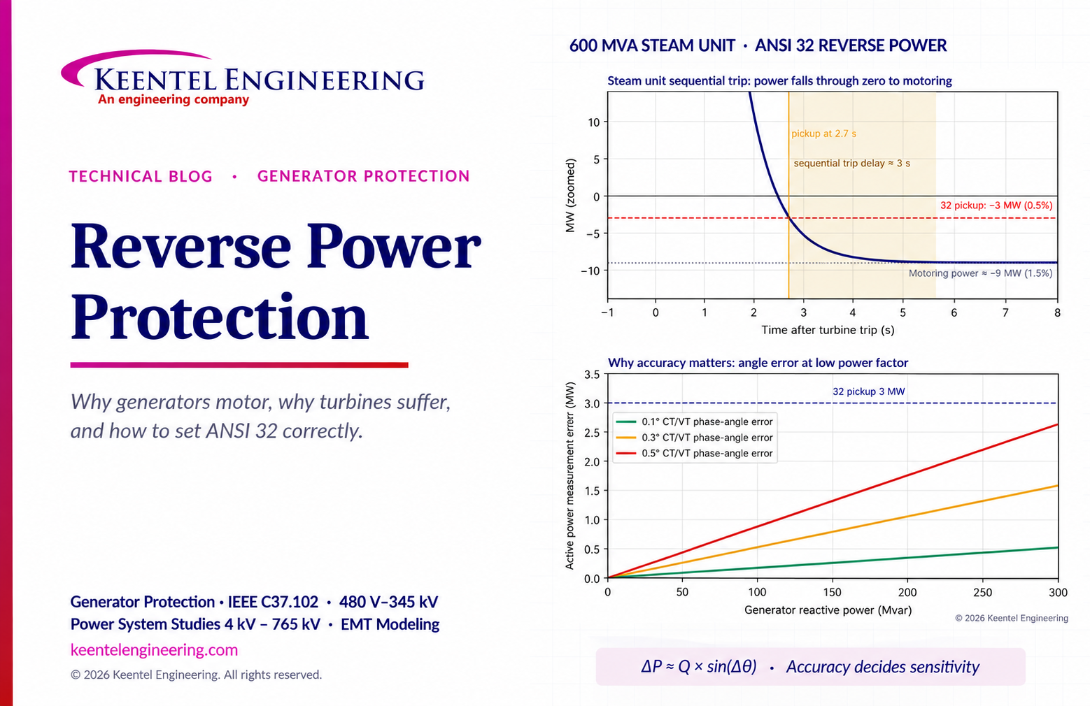
Learn reverse power protection (ANSI 32), generator motoring, relay pickup settings, time delays, sequential tripping and testing for US power plants.

By Team 2 Dexora
•
October 20, 2026
Explore grounding system testing with Keentel Engineering. Learn IEEE 80/81 methods, soil resistivity, ground resistance, and touch and step voltage safety.

By SANDIP R PATEL
•
October 13, 2026
Plan data center capacity with land screening, MW-per-acre estimates, grid power availability and interconnection feasibility studies from Keentel Engineering.





